Research Collection
Student Paper
People Counting System Using Wireless Sensor Nodes
Author(s):
Häberle, Marvin Publication Date:
2020-04-27 Permanent Link:
https://doi.org/10.3929/ethz-b-000414523
Rights / License:
In Copyright - Non-Commercial Use Permitted
This page was generated automatically upon download from the ETH Zurich Research Collection. For more information please consult the Terms of use.
ETH Library
People Counting System Using Wireless Sensor Nodes
Semester Thesis
Marvin H¨aberle marvinh@ethz.ch
Computer Engineering and Networks Laboratory
Department of Information Technology and Electrical Engineering ETH Z¨urich
Supervisors:
Stefan Dra˘skovi´c Andreas Biri Prof. Dr. Lothar Thiele
April 27, 2020
Acknowledgements
I have taken the main effort in this project. However, with the help and out- standing support of many individuals, this thesis would not have been possible.
To all of them I would like to extend my outspoken thank you.
Especially, I want to thank my two supervisors, Stefan Dra˘skovi´c and Andreas Biri. Their continuous support, great collaboration, and useful brainstorming made this project unforgettable and a lot of joy for me.
Also, I want to thank the whole Computer Engineering Group for opening me the opportunity of this interesting project in the first place.
i
Abstract
Using Wireless Sensor Networks (WSN) to connect hundreds of sensing de- vices to each other is indispensable in today’s connected and networked society.
However, the issue of powering all of these connected sensing devices remains a big challenge. Powering them through a main supply, such as wall power, is often not possible, as this would result in excessive installation costs and restricted de- ployment abilities. Changing the battery all the time is no option either, as this would not scale due to too high maintenance. This calls for harvestable energy, used to provide the required energy supply directly on the sensing devices.
Especially indoors, the amount of harvestable energy available for recharging is hard to predict. The reason is the dynamic nature of indoor sources, such as lamps and window blinds, strongly dependent on people being present. This the- sis focuses on the hypothesis, that more people present in a closed environment relates to more harvestable energy available. To experimentally investigate this, a WSN people counting system is implemented. This is achieved my using two Permamotes which communicate through OpenThread and CoAP. The gathered data from the Permamotes is sent to a host system, on which a back end and GUI interface is implemented - to analyze the sensed information. This thesis therefore provides a complete system to count people, that can be used to inves- tigate the hypothesis further.
The implementation was then tested to show its performance. The experiments showed promising first results, with the complete system working as expected and high accuracy of people counting in some scenarios. However, the experi- ments also show, that the next step is to increase the accuracy of the counted people for real-life scenarios, by gathering real-life data. Based on these data, the accuracy can be increase by implementing an advanced post-processor.
Using this system, it will then be possible to investigate the stated hypothesis at larger scale and in real-life scenarios.
ii
Contents
Acknowledgements i
Abstract ii
1 Introduction 1
2 Related Work 4
3 Background 6
3.1 Wireless Sensor Networks . . . 8
3.1.1 Thread Network - OpenThread . . . 9
3.1.2 Constrained Application Protocol (CoAP) . . . 10
3.1.3 Energy Harvesting . . . 11
3.2 People Sensing . . . 11
3.2.1 Active Detectors . . . 12
3.2.2 Passive Detectors . . . 13
3.3 Permamote . . . 14
4 Implementation 17 4.1 Simple People Detection . . . 19
4.2 Operating Modes . . . 20
4.2.1 High-Power Mode vs Low-Power Mode . . . 20
4.3 Advanced People Detection . . . 21
4.3.1 Integrating Other Sensors . . . 23
4.3.2 Configuration File . . . 23
4.4 Data Post-Processing . . . 24
4.4.1 Packet Structure Analysis . . . 25
4.4.2 Multi-Threading . . . 26
4.5 GUI Interface - Dash . . . 30 iii
Contents iv
5 Results 32
5.1 Testing Scenarios . . . 32 5.2 Further Tests . . . 34
6 Conclusion 39
A Declaration of Originality 1
List of Figures
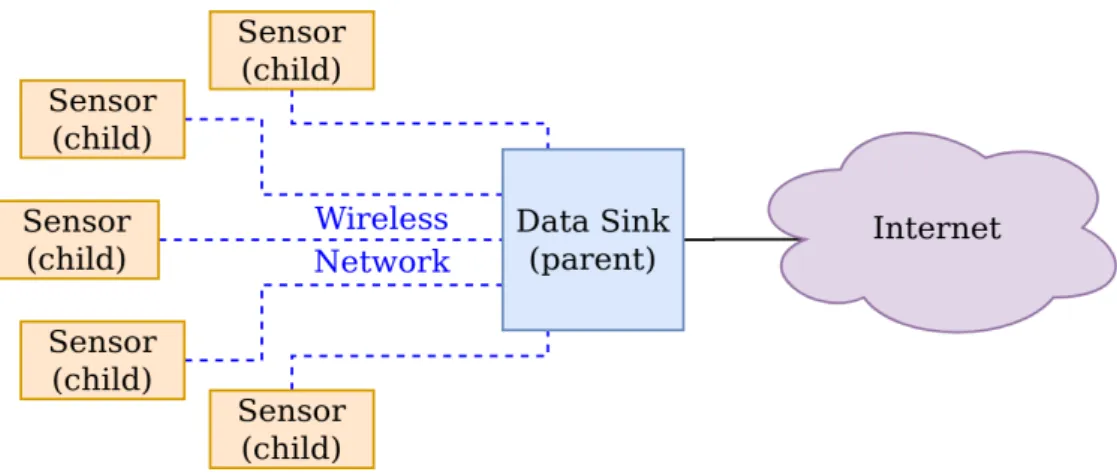
3.1 WSN, sensors (i.e. nodes/children) connecting via some wireless
connection to central sink (i.e. parent). . . 8
3.2 Opposite poled IR-elements placed in an alternated way, in order to detect motion in 2D [1] . . . 14
3.3 Fine-grained placement of IR-elements within a PIR-sensor, for higher detection accuracy withing the detection area [1] . . . 15
4.1 Final Application’s structure . . . 19
4.2 Setup, using two Permamotes . . . 22
4.3 Captured packet, containing different layer’s headers, as well as CoAP’s payload, called Data . . . 26
4.4 Captured packet, split according the the protocol the data belongs to . . . 27
4.5 CoAP’s packet content is being analysed in more detail, show- ing the important fragments with respect to the people detection application . . . 27
4.6 Multi-Thread . . . 29
4.7 GUI-interface . . . 31
5.1 Setup for verifying the implemented system . . . 33
5.2 5 seconds detection, 7 second time interval . . . 34
5.3 5 seconds detection, 5 second time interval . . . 35
5.4 4 seconds detection, 5 second time interval . . . 36
5.5 3 seconds detection, 7 second time interval . . . 37
5.6 Normal people count . . . 37
5.7 More robust people count, reducing the error . . . 38
v
List of Tables
3.1 Devices that can be connected to a single Thread network. 32 routers with 511 End Devices can result in a maximum number
of 16’352 sensing devices in a single Thread network. . . 10
3.2 Motion detection sensing methods . . . 12
3.3 Sensors integrated on the Permamote. . . 16
5.1 Reliability of different tested scenarios . . . 33
vi
Acronyms
6LoWPAN IPv6 over Low Power Wireless Personal Area Network.
BR Border Router.
CoAP Constrained Application Protocol.
FFT Fast Fourier transform.
HTTP Hypertext Transfer Protocol.
IETF Internet Engineering Task Force.
IoT Internet of Things.
IPv6 Internet Protocol version 6.
MCU Microcontroller.
NCP Network Co-Processor.
NTP Network Time Protocol.
PIR Passive Infrared Sensor.
SDK Software Development Kit.
SED Sleepy End-Device.
UDP User Datagram Protocol.
WSN Wireless Sensor Network.
vii
Chapter 1
Introduction
Wireless Sensor Networks (WSNs) and the Internet of Things (IoT) have ex- perienced a lot of attention in the last few decades. One type of application in the area of sensing are systems for people detection. In parallel to this, new ways of powering all of the sensor devices have been investigated. This led to an advancement of research into different ways of powering sensor systems, one very promising kind being the use of harvestable energy.
These days there is a large interest in WSNs, as more and more sensors are being deployed everywhere in our environment. It is not uncommon to have hundreds, if not thousands of sensing devices included into one system. WSNs allow to connect all sensing devices into a mesh-like network. The data can be sent over that network to a data-sink, where it is processed further. This type of network provides us with an efficient and scalable solution, based on well-known and robust protocols. Examples for this exist plenty. Some examples are smart buildings to regulate light and radiator, self-driving cars that observe and han- dle the surrounding traffic, or even sensors measuring the moisture of the soil of an agriculture plant, for example to automate the watering system - sensor are penetrating every part of today’s life. Within a building, the sensors are often distributed to measure on many different locations. Examples are smoke detec- tors, remote control of windows and doors, or automated temperature regulators.
An easy, inexpensive and scalable way to connect all the sensors is desired. This has strongly increased the interest into WSNs.
WSNs make it possible to deploy systems without infrastructure, but it is a challenge to power them. In indoor environments, it would also be possible to use a wired system, by using the wall power. Most often this is not the best solution, as this is too expensive due to high installation costs of the additional infrastructure required. Hence it would not scale well. However, establishing some kind of network is essential in order to be able to make any use of the sensed and gathered information on the nodes. Without any connection to send
1
1. Introduction 2 the data of all the distributed sensing devices to a central hub, no decision could be based upon these information.
To power the WSN, energy harvesting can be used, to recharge an intermittent energy supply. One could also aim for using a normal battery. However, replac- ing this battery all the time would be too expensive for maintenance. Energy efficiency is therefore one of the biggest concerns. The nodes should be operating for years - if not decades - in order to keep the maintenance at a minimum and hence allow great scalability. By using energy harvesting to power the device, operation over a long period of time without maintenance becomes possible. But especially indoors, energy harvesting brings the challenge of not knowing when in the future and in what quantities the energy will be available. To guarantee sensing at all time and only use energy-intensive tasks on the sensor when suffi- cient charge is available, it is important to be able to predict the energy available in the future. Predicting uncertainties as accurately as possible can decisively contribute for most-efficient and reliable operation, as the energy consumption can be adjusted, with respect to its availability.
In this thesis, the overall goal is to improve the prediction of harvestable en- ergy. To do so, the hypothesis we plan to test is the following: If people are present within a building, the harvestable energy available increases, compared to if no people are present. Besides this, if the number of people present in- creases, also the amount of available harvestable energy increases.
The goal of this thesis is to implement a system, to count the number of people currently present in an observed indoor environment. For this we used an ex- isting WSN node, called Permamote. The Permamote includes passive infrared sensors, which are used for detecting motion. Including multiple Permamotes into our system allows us to count the number of people. The great challenge is to predict the people present accurately enough, to be able to use this imple- mentation to prove or disprove the mentioned hypothesis. Secondly, we want to provide ground truth of the harvestable energy with the help of the on-board LUX meter. By implementing the LUX sensor to gather data about the light intensity, the available energy for a solar source is monitored. Thirdly, we aim to help researchers analyze and investigate gathered data in an easy and straight- forward way. To do so, a post-processor and a GUI interface running on the host computer are implemented. While the post-processor includes a Thread specifically for programming an accurate and adjustable motion counter, the GUI interface plots and displays all relevant data to easily analyze them.
Outline The remainder of this thesis is structured as follows: Chapter 2 relates this work to previous work that has already been written in this field, after which Chapter 3 provides a more detailed description of the challenges and required background knowledge with respect to networking, motion sensing, and devices being used. In Chapter 4, we explain how the people detection application has
1. Introduction 3 been implemented. First, the different parts of the implementation are being explained in detail, before Section??puts all the pieces together. Having handled this, Chapter 5 presents the results of testing the implementation’s performance and discusses the gathered results. In Chapter 6, we summarize the achievements as well as draw a conclusion.
Chapter 2
Related Work
The great interest in the field of WSNs has pushed the development of low- energy, high-reliability networking. New types of network protocols, tailored for sensing applications and simplifying their deployment, have been invented over the years [2].
Many systems for detecting people have been designed, utilizing an endless number of different sensors, such as active and passive infrared sensors, ultrasonic sensors and microwave sensors. As this thesis is concerned with detecting people using the passive infrared sensor (PIR), only papers related to this kind of sensor have been taken into account.
In the past several different measuring methods have been proposed, most of which are additionally concerned with machine learning for post-processing the gained data. Jaeseok et al. [3] have studied human movement detection using three PIR-sensors placed in a hallway. Different walk-through scenarios have been recorded and the gathered data has been used in order to train a machine learning model, classifying the different scenarios. The focus was on detecting direction and speed of movement. Yordan et al. [4] have shown in their paper, that by using only a single PIR sensor in a room, it is possible to detect the number of people present with high accuracy, using different machine learning algorithms. For example, when having a room occupancy of eight people or lower, 80% of the time the system correctly predicts the number of people with a maximal deviation of less than one person.
As far as indoor energy harvesting is concerned, various approaches have been proposed, relating the life-time of the device to the amount of energy available to be captured. Especially, the importance of energy harvesting for WSNs has been shown [5], as for such devices energy consumption, as well as maintenance costs appear to be a real bottleneck. Another important research area is the speed and efficiency with which harvestable energy can be used for recharging a source.
This increases the amount of energy that can be absorbed. Wensiet al. [6] have 4
2. Related Work 5 proposed a solution with a novel charge circuit in their paper. By increasing the speed and efficiency of charging, more reliable predictions, concerning the certainty for having enough harvestable energy available in the future, can be made.
Wireless communication is important for WSNs, as this allows communica- tion between the different devices, as well as forwarding gathered data from the sensors. Especially for low-power, local networks, primarily concerned with in-frequent and low-bandwidth data, WSNs are extremly interesting. Different networking protocols are available to be chosen from, such as Bluetooth Low Energy [7], Z-Wave [8], ZigBee [9], or 6LoWPAN [10] based on top of the IEEE 802.15.4 standard.
Chapter 3
Background
In WSNs deployed indoors, it is of vital importance to enable their long- term operation. For outdoor deployments, equipping nodes with harvesters of ambient energy is an often-used solution. However, indoor environments feature 1000 times less light energy [11]. This makes their powering by using this form of energy much more challenging. The longevity of indoor sensor nodes is often a presumed requirement, but at the same time the greatest challenge. The sensors record events and communicate with a central server, over a wireless connection. In WSNs especially, when there is a large number of nodes, it helps if the maintenance of devices is minimized. Otherwise the amount of sensors being distributed and powered would not scale. Firstly, the sensors must consume the lowest amount of power available, in order to prolong the lifetime of the sensor system as much as possible. Secondly, in order for the device to be able to perform for years - or even decades - without any maintenance, the call for an on-board charging technique becomes louder, motivating the use of harvestable energy for indoor applications as well. Imagine we have a sensor with primary (i.e. non-rechargeable) and secondary (i.e. rechargeable) energy sources. We want to use the harvested energy as much as possible, but can make use of the non-rechargeable battery if necessary. One of the most energy-intensive tasks is to send the data over a wireless connection. If the sensor node could know, that enough harvestable energy were to be available in the close future, the device could wait with sending the data up to that moment. The sensor chooses to only transmit information when it has sufficient energy stored in its rechargeable battery. In that way the non-rechargeable energy source of the device can be saved.
Besides having large harvesters, one way to tackle the uncertainty of low and intermittent energy sources is to predict its availability. In indoor environments, the energy available to recharge a sensor node on-board is connected to many uncertainties. Compared to outdoor, in general there is less energy available that can be harvested. Predicting this energy can prolong the life-time of the device.
Especially, the prediction allows us to dynamically adjust energy consumption, 6
3. Background 7 as energy harvesting can be used with more certainty. This thesis tries to tackle just this challenge, by providing a system to be used to better predict the avail- able energy in indoor environments. To do so, we introduce the following two hypotheses:
Hypothesis 1:
The (photo-voltaic) energy available within some indoor environment correlates to the presence of people inside that environment.
Hypothesis 2:
The amount of (photo-voltaic) energy available correlates to the number of people present. The more people are present, the more solar energy is available
to be harvested and used.
To verify or disprove these hypotheses, a system to count the people present is implemented in this thesis. The correlation between the amount of people present and harvestable energy available (i.e. the second hypothesis) is not expected to be linear. This means that already one person within the monitored environment is expected to have a great influence on the energy available. Any further person present is expected to have a smaller influence on the available energy. The reason for this is that already the first person will for example turn on most lights, or open the window shutters. Hence, to prove or disprove the second hypothesis, a high accuracy of the people counted has to be achieved.
Let us use an example to justify this hypothesis, by assuming that it is Sunday.
In a fictive company nobody is normally working, all the shutters and windows are closed and all the lights are turned off - in order to safe power. Nevertheless, this day it is different. Due to an approaching deadline an employee decides to go to work. To not feel as lonely, he opens all the windows and turns on the lights to bring some life into his office, which increases the light intensity (LUX) inside the office. A sensing device will regularly communicate this information to the central server, to inform other sensors and improve their performance at run-time. The unforeseen sudden available harvestable energy can therefore influence of how deployed low energy sensing devices process and handle their data.
This chapter will first explain in Section 3.1 what WSNs are, as well as the used protocol on the networking layer and application layer. In Section 3.2, the sensors available for people sensing are explained. The focus is on the passive infrared sensor, which is used in this thesis. The used sensing device, the Permamote, is explained in Section 3.3.
3. Background 8
3.1 Wireless Sensor Networks
In the last years wireless sensor networks have rapidly emerged in markets of a great amount of different multidisciplinary fields. It is fair to say, that WSNs are a big research field of the past years and the advantages of WSN technology over conventional networking solutions have been shown in various scenarios [2].
Figure 3.1: WSN, sensors (i.e. nodes/children) connecting via some wireless connection to central sink (i.e. parent).
From a general point of view, a WSN refers to a group of end-devices - referred to as nodes (i.e. children) - which are then connected via some wireless connection to a central location (i.e. parent) [12], as illustrated in Figure 3.1. The parent, known as data-sink, is normally a wall-powered device, not as energy constrained as the nodes. At the same time, it receives the data from all its children. This allows the parent to process the received data further. Also, the data sink has a connection to backbone infrastructure, via a wired internet connection, allowing it to send the data on to a host computer. The end-devices, which are spa- tially dispersed in some given area, may include one or more sensors, dedicated to observe environmental conditions. They are further equipped with a radio communication interface (for wireless communication), some amount of memory (to intermediately store gathered data, as well as programs), power supplies (to operate for a long period of time), as well as an MCU (to control the device’s behavior) [2].
To keep the power consumption of the children at its minimum, two most im- portant factors have to be considered within the WSN. Firstly, the nodes should be in a low-power mode as often as possible. It is therefore important to only perform sampling operations as much as needed, to get an acceptable amount of information. Hence the end-devices are referred to as ”sleepy devices”, meaning they do not have their transceiver enabled all the time. Having the data-sink always ready to receive information from its children, allows for reliable com-
3. Background 9 munication. Hence, it makes our life much easier if the data sink’s transceiver always remains enabled. Secondly, the most energy consuming part is the trans- mission of data via a wireless connection. Regardless, this is an essential part of any WSN, allowing to further process the acquired data at the data-sink and base decisions upon them afterwards. As most WSNs are designated to operate for many years, without any human being needed to maintain the devices, it is common to use on-board energy harvesting to recharge the devices.
Summarizing, low costs, scalability, versatility, flexibility, and ease of deploy- ment have been the main drivers that pushed the technology of WSN to be used in a wide range of applications. In agriculture, WSN technology is being used to improve for example crop production [13]. Forest fire can be forecasted more promptly, using WSN [14], or the structural health of civil infrastructure can be monitored, reducing investigation and visual inspection costs [15].
3.1.1 Thread Network - OpenThread
The Thread protocol [16] is a very widely used communication protocol, pro- viding an energy-optimized protocol based on IEEE 802.15.4 radio standard, using 6LoWPAN. It has been specifically developed for the Internet of Things (IoT), allowing to use the IPv6 standard to create a mesh network.
Thread enables the possibility to connect hundreds or thousands of devices to a mesh-like network, without high configuration and maintenance. The mesh-like network has self-healing characteristics and devices can be added or removed from the network, without manual configuration necessary. Additionally, the fact that Thread uses IPv6 based networking between the sensor nodes makes it for any WSN very easy send the data to any centralized server, witout knowing the network. It is only necessary to configure the sensor nodes correctly. The IEEE 802.15.4 itself has also been built for the purpose of low power consump- tion. Using an optimized protocol on top of this provides the best available technology to fulfill low power requirements. These facts make Thread the per- fect wireless-protocol for WSNs.
Types of Nodes
Any Thread network includes two main types of nodes, namely the routers (i.e. parent) and end-devices (i.e. child). It is important to notice, that every child connects to exactly one parent. The parent’s main task is to handle and forward packets arriving from its children. Its transceiver therefore always listens for communication, hence the router always remains enabled. A router can be configured as Border Router, which allows it to forward traffic between a Thread network and a non-Thread network.
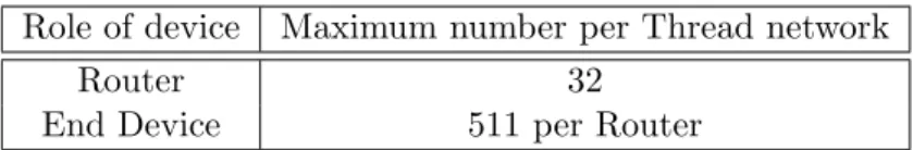
3. Background 10 A child on the other hand is not forced to listen to incoming traffic. This allows the child to enter a sleep-state by disabling its transceiver and saving power, referred to as sleepy end-device (sed). A child can also be seen as a sensing device, which sends acquired data on occasion towards its router. For a Thread network, maximum device restrictions apply, as listed in Table 3.1.
Role of device Maximum number per Thread network
Router 32
End Device 511 per Router
Table 3.1: Devices that can be connected to a single Thread network. 32 routers with 511 End Devices can result in a maximum number of 16’352 sensing devices in a single Thread network.
OpenThread
An open source implementation of the Thread protocol, called OpenThread [17] has been released by Net Labs and Google. This implementation provides all Thread networking layers [18], including:
• IEEE 802.15.4 with MAC security
• IPv6 and 6LoWPAN
• UDP packet compression
• A CoAP implementation
The networking of the thesis will be based upon the OpenThread implementa- tion.
3.1.2 Constrained Application Protocol (CoAP)
When forwarding packets through some Thread network, the payload of those packets has to be handled by some Application Layer Protocol. For wireless machine-to-machine communication between nodes of low-power con- strained networks and building automation, the Constrained Application Proto- col (CoAP) has been developed by the Internet Engineering Task Force (IETF) [19]. An important feature of CoAP is that it provides easy translation to HTTP, the commonly used protocol for the world-wide-web. This allows low-energy sub nets, such as Thread, to connect via some interface (i.e. via the Border Router) to the global internet. High reliability in a low-energy networks is therefore preserved by using the simple and energy-optimized CoAP - including features
3. Background 11 such as low overhead, asynchronous message exchange, and discovery support.
Nevertheless, easy interfacing towards the bigger internet remains possible, as CoAP is designed to easily translate to HTTP.
3.1.3 Energy Harvesting
Harvestable energy refers to the energy available in an environment that can be captured by some energy harvester (e.g. a solar panel). The best known forms of energy available to be harvested are solar power, wind energy, kinetic energy, as well as thermal energy. The process of capturing this available energy is called energy harvesting. Relating the amount of harvestable energy available in an indoor environment can be much more challenging compared to outdoor harvesting scenarios. The reason for that is on the one hand the dependency upon more unpredictable events, which occur with respect to the behavior of human beings. On the other hand, in an indoor environment the amount of harvestable energy available is in general way more restricted compared to the outside. While outside the amount of available energy is mostly dependent on the weather conditions, this is unmistakably not the case indoors.
3.2 People Sensing
Movement of people within a given area can be sensed in various ways. Some of the most well-known techniques used these days, to detect motion and pres- ence of humans are depicted in Table 3.2. The presented sensing methods vary in their technology and sensing mechanism, which results in different trade-offs regarding their properties, such as sensing accuracy, power efficiency, range, sen- sitivity, and reliability. In order to determine the most reasonable sensor within a WSN system for an indoor people detection application, an analysis about a fundamental trade-off between accuracy and energy consumption has to be per- formed.
When using WSNs, one of the large constraints one always has to take into account is its energy efficiency. Depending on the scenario, we must chose the most-fitting method that provides the sought-after degree of accuracy while min- imizing power draw. Accuracy refers to how well the presence of people can be determined. While a sensor with low accuracy might only be able to predict the amount of people present, a sensor with high accuracy might count the actual number of people currently there.
People sensing using video cameras is of course an important and largely used technology in today’s society. The development and available systems using video cameras is immense, as the fields of machine learning and com- puter vision evolve more and more in the market. However, these kind of
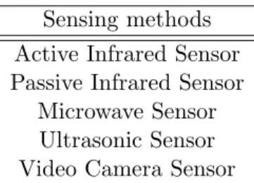
3. Background 12 Sensing methods
Active Infrared Sensor Passive Infrared Sensor
Microwave Sensor Ultrasonic Sensor Video Camera Sensor
Table 3.2: Motion detection sensing methods
systems are also known for having a large energy consumption. Further, they have mainly been developed for people recognition. For this reason, today’s state of the art camera sensing systems are not applicable for low-energy sys- tems and this technique of people detection is not taken into account any further.
Two main types of motion sensing mechanisms are available, namely ac- tive and passive detectors.
3.2.1 Active Detectors
As the name already suggests, active motion sensors consist of a part that actively sends out waves, called transmitter. These waves are then re-captured by another sub-part, called receiver. Waves are being sent in form of radio waves or microwaves. Two different operating modes of active sensors are taken into account [20].
The first mode of operation is by analysing reflected waves. As soon as an object moves in the area, which is controlled by the sensor, the receiver of the sensor senses the Doppler effect taking place. These kind of sensor have the ability to sense even small movements in the direction perpendicular to the sen- sor. Microwave detectors [21], as well as ultrasonic detectors [22] belong to this category of sensors. These type of sensors are widely used in the field of robotics and obstacle avoidance.
The second type of operating mode is by separating transmitter and receiver into two devices, using infrared rays in between them. The beam from transmit- ter to receiver has to cross the detection area. As soon as an object enters this just mentioned detection area, the beam gets interrupted. This interruption is registered as an object that has moved into that area, hence motion has occurred.
The active infrared detector is an example of this kind of sensor [23].
The disadvantage of these kind of sensing mechanisms is their permanent and comparatively high power consumption, coming from their constant transmission
3. Background 13 of waves. However, if the active sensor would not not constantly transmit waves, it could miss some motion event occurring in between. To avoid this constant power emission, passive sensors can be used. This lowers the consumption of the sensing devices as much as possible for WSNs, but comes hand-in-hand with a loss of accuracy.
3.2.2 Passive Detectors
As opposed to active sensors, passive sensors do not send out any kind of waves, but simply register changes in the environment - by observing infrared waves that are sent from heat-emitting objects such as warm human bodies. This makes passive sensors very efficient and easy to use on the one hand. On the other hand, however, a trade-off between power consumption and detection accuracy has to be taken into account. Passive sensors work by observing changes in temperature of some region within their observed range. It triggers upon changes in heat registered. This happens, as soon as an object that radiates another temperature compared to its environment moves within the range of the sensor [20]. These kind of sensing devices are more prone to false positives of detecting humans. This is due to the fact that for example a change in light intensity, or the radiation of heat from a radiator, can also cause the triggering of the sensor.
Therefore, passive sensor are perfect for controlled indoor environments, as less unpredictable motion events and temperature changes occur. For this reason - and for their much lower power consumption, as systems do not have to actively transmit but can only sense - these kind of sensors are very interesting for low- power WSN applications. The most widely used passive motion sensor is the passive infrared sensor (PIR), which will be explained in more detail.
PIR sensor Passive infrared sensors (PIR) are based on pyroelectric detectors.
The working principle of these kind of detectors is based on two IR-sensitive elements with opposite polarity. The detector has the capability to develop an electric field between these two IR elements, which appears as soon as one of the elements experiences a change in temperature [24]. State-of-the-art PIR sensors being used in today’s industry include many IR-sensitive elements, alternating the polarities in a mesh-like grid. This gives these sensors the ability to detect motion in two dimensions. Refer to Figure 3.2 for an illustration. The figure shows four elements, alternating the polarity to each other. Any heat object entering from one of the four sides and covering the two closest elements will cause the sensor to trigger. Additionally, the fine-grained placement of IR elements within a PIR sensor increases the detection accuracy, meaning that already small movements within detection range can be detected. Often 40 and more of these sensing elements are placed within one single sensor, refer to Figure 3.3. As soon as any two elements register a voltage difference, a motion detection is being triggered through the voltage difference of exactly those two elements.
3. Background 14
Figure 3.2: Opposite poled IR-elements placed in an alternated way, in order to detect motion in 2D [1]
Most commonly used PIR-sensors have three pins attached to it: HIGH, LOW and OUTPUT. Whereas the first two pin provide the supply voltage, as well as the ground level, the OUTPUT pin switches from LOW to HIGH as soon as a voltage is detected between any two adjacent and opposite polarized IR- elements. It is very important to notice that any PIR-sensor can only sense motion somewhere in the area of its range, but but cannot distinguish where within that area. The consequence is that it is not possible to sense multiple different motion-events occurring at the same time within a single PIR-sensor’s range, as these different events are not distinguishable. They will simply be registered as motion detected, resulting in a LOW-to-HIGH transition on the OUTPUT-pin.
3.3 Permamote
Permamote [25] is a small hardware device that has been developed by Neal Jackson et al., at the University of California, Berkeley. The device features six different sensors - one of them being a PIR-sensor. A great advantage of the Permamotes are the two different energy sources of the device. It includes a primary voltage source - which is a normal battery - as well as a secondary voltage source, which is a rechargeable battery. As the secondary energy source, an indoor photo-voltaic cell has been integrated into the system, which allows the secondary source to be recharged on-board. All of these modules, as well as a radio, are placed around an nRF52840 microcontroller (MCU), which enables this device to be used as a very low power node of a WSN.
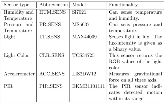
For completeness, in Table 3.3 all sensors available on the Permamote have been listed. The first column names the type of sensor, the second column provides an abbreviation being used for the sensor and the third column shows the model.
3. Background 15
Figure 3.3: Fine-grained placement of IR-elements within a PIR-sensor, for higher detection accuracy withing the detection area [1]
This device has been chosen to be used as the basis for developing and im- plementing the people counting application in this thesis, due to several distinct reasons. Multiple of these Permamotes can be connected to form a WSN, via an OpenThread network. This allows for scaling, as well as sending all data to a central server, which can then process the data and combine the different sensor streams. Another advantage is that different kind of sensors are available on the Permamote, which can be used to increase the accuracy of the people detection, by supporting the PIR sensor with additional environmental information. The Permamote is further optimized for energy efficiency and has been implemented for indoor environments. Using the harvestable solar energy available to send the gathered information of the sensors via the Thread network towards the Border Router allows operation at very low energy consumption without any maintenance overhead. This guarantees operation for over 10 years, without any required maintenance.
Last but not least, one other main reason for using the Permamote is to further explore the abilities and capabilities of the device itself.
The PIR-sensor integrated is the EKMB1101111, as stated in Table 3.3. The sensor has a detection-range of 5m, whereas its horizontal and vertical angle of detection is 94◦ and 82◦ respectively. The PIR-sensor is subdivided into 64 detection zones (refer to Section 3.2.2), which provides a good resolution in the range of the sensor. Figure 3.3 has been taken from [1], in order to visually show
3. Background 16 Sensor type Abbreviation Model Functionality
Humidity and Temperature
HUM SENS Si7021 Can sense temperature and humidity.
Pressure and Temperature
PR SENS MS5637 Can sens pressure and temperature.
Light LT SENS MAX44009 Senses light in lux. The lux-intensity is given as a binary value.
Light Color CLR SENS TCS34725 This sensor returns the RGB values of the light color.
Accelerometer ACC SENS LIS2DW12 Measures gravitational force on all three axis.
PIR PIR SENS EKMB1101111 The PIR sensor indi-
cates detected motion within its range.
Table 3.3: Sensors integrated on the Permamote.
one dimension of detection range and its IR-element placement. This figure refers to the vertical range.
Chapter 4
Implementation
Detecting the presence of people can be done in many different ways, as has been explained in Section 3.2. Several aspects were to be achieved within this work, which can be summarized as follows:
1. Using the Permamote to create an application to detect the presence of people in some closed and well-defined environment. This applica- tion should enable the ability to relate the presence of people to available harvestable energy in the same environment, as explained in Chapter 3.
2. The people detection application should be implemented as a low-power application, supporting different modes of operation. The aim is to use the secondary battery as much as possible, in order to keep the lifetime of the device as high as possible, without maintenance requirements.
3. In a second iteration step, the application was to be improved in terms of people detection accuracy as well as power efficiency. While the first aim was simply to detect the presence of human beings in general, the improved applicationcounts the number of present people. This improvement is achieved by including multiple Permamotes into the system and combining multiple PIR-sensors.
4. The application is to be embedded in a complete and well-functioning sys- tem, based on a WSN, where the sensing devices are connected via OpenThread to a Border Router. This enables the gathered data to be sent from the Permamotes, parsed, interpreted and further investi- gated on some central server. Further, the Permamotes are relieved from computational burden, increasing their lifetime even further.
The Permamote offers a platform, perfectly tailored for low-power WSN appli- cations. Its integration of a combination of sensors, together with its ability to choose between two energy supplies - based upon the availability of harvestable energy - seems to make it an incomparably well fitted platform. Due to these
17
4. Implementation 18 facts the occasion of investigating the abilities of Permamote further, encouraged the decision to implement the people-detection application on this platform. As the Permamote relies on a PIR sensor to detect people, a single device can only detect motion in general. Therefore, any implementation is bounded to only work correctly if some general conditions are given. This application has been designed designed to work in an environment, respecting the following conditions:
• The implemented system has been designed to work in closed indoor envi- ronment. ‘Closed’ refers to an area, to which there is only access through one single entrance. This means that anybody entering or leaving that area has to pass through that entrance.
• The closed area has a known number of people inside at the moment where the Permamote/Permamotes are being put into operation.
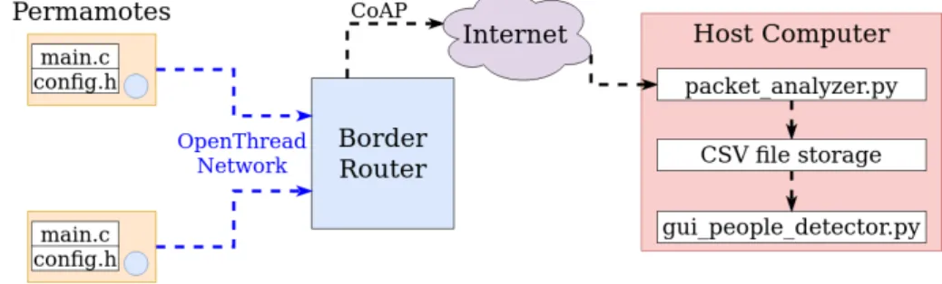
Final Application Structure: The final application has been built in an it- erative process, including different major steps. The final system contains three main implementations. On the Permamotes, a program handling the device and its sensors is implemented. On the host-computer, a program post-processing the gathered data from the Permamotes is implemented. The third implemen- tation, also on the host-computer, provides a GUI interface, making if easy for any researcher to analyze all the information gathered of the people counting application. The overall goal is to provide a flexible system that is able to accu- rately count people and is easy to be installed and used. To provide flexibility, we use a WSN, which makes it very easy to include additional sensors. At the same time, the system should provide an easy way to analyze data, which is achieved by integrating a GUI. The challenge is to arrive at a high people count accuracy, while using a low power sensor. To achieve this, multiple PIR sensors are integrated within the system. Further, long lifetime and low maintenance of our system are important. To overcome this challenge two different modes are implemented, whereas one keeps the energy consumption at its lowest if not enough harvestable energy is available to be used. An overview of the entire system is provided in Figure 4.1, showing the the names of all implemented pro- grams and their place within the whole system. The remainder of this chapter explains the different parts of this system in detail.
Permamote Setup The implementation on the Permamotes is implemented in C-code, embedded in the Permamote repository [25]. The structure inside the repository can be found to be as follows:
Permamote software
apps
4. Implementation 19
Figure 4.1: Final Application’s structure people detection
main.c config.h app.h README.md
As the Permamote is based upon the nRF52840 SoC from Nordic Semicon- ductors, the above mentioned repository integrates Nordic’s software develop- ment kit (SDK), version 15.3.0 for Thread and Zigbee [26]. The people counting application therefore makes use of this SDK as well.
4.1 Simple People Detection
The simplest way to detect people’s presence is by registering any event of motion within an area. Let us for this purpose consider a room, for example a small office. A single PIR sensor can be placed in such a way, that the majority of the room of a small office is covered by the range of the sensor. This enables the detection of most of the movement within the room. Of course, this kind of people detector does not try to count the amount of people present within this area. However, as has been explained in Chapter 3, the correlation between number of people present and amount of available harvestable energy is not as- sumed to have a linear correlation. This means, as long as a single PIR-sensor can predict people being present in general, a correlation towards available har- vestable energy should already be possible.
Due to this fact, the first step to a working systems was twofold. From the application’s implementation point of view, the first step was to implement the PIR-sensor to count the motion events happening within a certain time. The PIR-sensor is set to its sense state, while the remaining systems remains in a low-power mode, in order to conserve energy. As soon as the PIR-sensor detects motion, the system’s nRF chip is triggered to wake up and handle the detected motion.
From the whole system’s point of view, the Permamote is just the sensing device,
4. Implementation 20 called the node of the system. In a later phase of the implementation it will be important to handle the data gathered by the Permamote further, using a WSN setup. A Thread network topology is established, using the OpenThread imple- mentation. In order to do so, the following, already available hardware-setup is put into operation: A Raspberry Pi B+, loaded with an OpenThread Border Router image [27], is set up. An nRF52840 Dongle [28] is used as network co- processor (NCP), plugged into the Border Router and loaded with an already available system NCP-software [29]. The NCP establishes the Thread connec- tion towards any active Permamote, whereas the Border Router has the ability to either forward the received packets further over an Ethernet connection, or handle the data itself.
4.2 Operating Modes
The nRF52840 SoC has the ability to remain in a very low-power mode during most of the time. It can be woken up through external interrupts, to process some occurring event. It is desirable for a low-power device to choose between different scenarios, on when to switch between low-power and higher-power operation states, based on the amount of energy available. As mentioned, the Permamote provides two energy sources that can be used, one of them being an energy harvester. Therefore, two different modes of operation are implemented to most efficiently use two different energy sources. These two modes are a high-power mode, while enough energy is available in the secondary (i.e. rechargeable) battery, and a low-power mode, for the case that the primary battery (i.e. not rechargeable) has to be used for operation. The energy consumption is therefore adjusted by switching between the different modes of operation. This allows to operate with rechargeable energy whenever possible, prolonging the lifetime of the non-replaceable batteries.
4.2.1 High-Power Mode vs Low-Power Mode
The high-power mode differs from the low-power mode in the way the packets are being sent over the wireless connection. As with any sensor operating as real-time application, it is not possible to change the moment of sensing. This is due to the fact, that sensing needs to be done in real-time and cannot simply be delayed to a later moment, as the events to be sensed cannot be delayed. There- fore, the device always needs to wake up for any kind of sense event of interest.
However, the handling of the gathered data can be adjusted. High-power mode directly sends gathered motion events to the Border Router, allowing real-time post-processing of these data.
The low-power mode, on the other hand, stores the gathered data on the Per- mamote and sends them towards the Border Router at some later point in time.
4. Implementation 21 Let us assume the device operating with primary battery, as the secondary bat- tery’s charge state is too low. If now a lot of harvestable energy is available, the low-power mode allows to delay the sending of packets, until the secondary battery has been charged enough to be used again.
It is important to notice, that the Permamote itself chooses upon the primary or secondary battery to be used. The choice is simply based on the charge state.
While the secondary battery is being used, a flag - called VBAT OK - is raised, which is read by the MCU. However, the choice between which of the imple- mented power modes should be used, is based on measuring the actual voltage of the secondary battery. The reason for doing so is to allow more flexibility:
Choosing when to switch from low- to high-power mode can be easily adjusted by the user - by simply adjusting the voltage threshold of the secondary battery for switching.
The reason for implementing the behavior in this way becomes obvious when considering the following fact: As soon as the secondary battery has been charged to a level, that allows it to be used as energy source, VBAT OK will indicate so. Assuming that the state is now directly being switched to high-power mode might drain the battery to immediately drop below the VBAT OK threshold again, resulting in a toggling between the different modes of operation. This is prevented by implementing the threshold to be adjustable to the user’s needs.
Next to choosing the mode through the battery charge state, it has also been implemented to manually select the operation mode as user directly. This enables to overrule and set one of the modes to be used, not taking into consideration the battery’s charge state at all.
In order for the user to configure the application in a simple and straightfor- ward way, a configuration file has been implemented. Within this file all relevant parameters can be set for the application. The file’s structure and functionality is explained in more detail in Section 4.3.2.
4.3 Advanced People Detection
After having established a first working people-detector, different aspects to improve this implementation have been taken into account. The biggest challenge being tackled with this advanced implementation is for people to be counted, instead of only distinguishing between presence and absence of people in general.
This brings some additional challenges, because a single PIR sensor has no sense of direction of the detected motion, nor the number of simultaneous motions detected. Two different approaches were considered to overcome these issues.
4. Implementation 22
Figure 4.2: Setup, using two Permamotes
One approach is to use classifiers, as to estimate an accurate number of people in a certain area. This requires a high amount of post-processing of gathered data, using machine learning and other statistical approaches, which is by no means easy to implement. Additionally a lot of data must be gathered before- hand, to be able to use data for predictions and models.
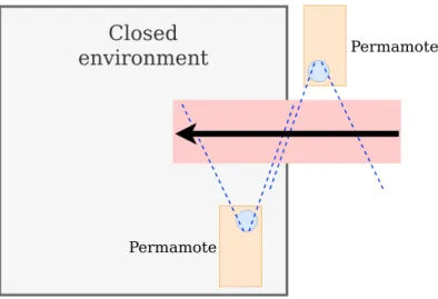
As such heavy processing is unsuitable for low-power implementations, a second approach has been chosen, which includes a second Permamote (i.e. a second PIR sensor). Further considering the assumptions made at the beginning of this chapter, the setup to count the number of people present within a closed envi- ronment is illustrated in Figure 4.2. Any person entering or leaving the closed environment is crossing the range of each of the two PIR-sensors, whereas one of them is placed withing the environment and the other one outside of it. As soon as a PIR-sensor detects an event of motion, it starts sampling for a user-defined period of time, e.g. two seconds. As the PIR-sensor is equipped with 64 detec- tion regions (refer to section 3.3), multiple motion-events will be triggered during these two seconds. All motion events during these two seconds are summed up and the gathered data is stamped with an NTP-synchronized time. This setup makes it possible to detect the direction of any person crossing both sensors, with the help of the acquired timestamps on both sensors. As people enter the area, the timestamp of the Permamote placed outside of the environment will indicate an earlier time compared to the other Permamote. If the timestamps are within a certain margin to each other, the event counts as a person entering the room. At the same time, taking the timestamps allows us to handle some false-counts. Let us assume only one sensor registered motion within a certain time-span. This can be due to a sudden change in light intensity, a human being entering the range of the sensor without actually leaving or entering the moni- tored environment, or some similar scenario. The Permamotes do not have any
4. Implementation 23 timestamps within a certain margin in this case, meaning that nobody entered or left the room.
4.3.1 Integrating Other Sensors
Additional sensors are available on the Permamote. It is possible to use them, to arrive at an application with the ability to correct false measurements of the amount of people present over time. This is an important requirement for accuracy and robustness of the application.
To correlate people’s presence to the amount of energy available as accurately as possible, the application must fulfill some crucial requirements. First of all, it is clear that measurements are to be taken over a long period of time, to be able to accurately evaluate the hypothesis (Chapter 3). It can always occur that the people counted within the monitored environment is not completely accurate. Especially the trade-off towards accuracy, by using a sensor as simple as the PIR-sensor validates that fact. This is undesirable, but at the same time unavoidable with hundred per cent certainty. One possible scenario explaining this issue is, if two people leave the gateway in the same sampling period of time.
The two persons would only be registered as one. To completely prevent this from happening is a close to impossible task. Therefore, more importantly, this error needs to autonomously vanish over time. Only then it can be guaranteed to monitor the presence of people with a high enough accuracy over a long period of time, if a change in number of people present should be correlated to a change in harvestable energy available.
To achieve the just explained requirements, the light sensor in combination with the PIR sensor and timers are used. The reason for this implementation choice is the following: In any realistic scenario, there is a period of time every day, where normally nobody is present in the monitored environment for a few hours. This is usually at night. Therefore, as soon as the light intensity falls below a defined threshold (i.e. indicating ’night’) and no motion has been de- tected for a long enough period of time (e.g. four hours), the application has the ability to correct itself by automatically setting the currently registered present people back to zero. This shows one way how additional sensors can be used to increase the accuracy of people counting.
4.3.2 Configuration File
For a user to handle the implemented application in a straight-forward way, it needs to be easy to adjust all variable parameters within the application.
To facilitate the handling of the application, a configuration file, config.h, has been added. This enables a user to adjust all parameters, without diving into
4. Implementation 24 the code of the application’s implementation, and is structured in the following three parts:
1. MODE SETTING: This part relates to Section 4.2. The user has the option to either set the threshold of the charge state to switch between the modes manually, permanently set one of the two modes. Further, the time period with which the Permamote should send the packets in low- power mode can be specified, as well as the maximum number of packets that can be stored inside the local memory of the Permamote, in order to pre-allocate the memory.
2. NETWORKING: It is important to decide if one wants to specify an address, towards which the sent packets are being directed. The default address is defined as ’COAP SERVER HOSTNAME’. To overwrite this address, one simply has to set ’COAP CUSTOM DEST ADDR’ to the public IPv6 of the desired destination.
3. TIMING:In this section all timers that are active can be re-adjusted. The most important parameters to adjust, however, are ’PIR SENSE PERIOD’
and ’PIR TIMEOUT’. These timers decide upon how long the sensor keeps detecting, after registering a first event of motion, and the time the sensor remains disabled after this period is over respectively. Hence, the sys- tem is able to adjust its detection period to P IR SEN SE P ERIOD+ P IR T IM EOU T. These two two parameters are combined as one com- plete detection period during evaluation later on.
Some parameters can only be set to ideal values after some amount of experimental testing. This is due to the fact, that they depend on individual deployment setup of the people counting system. One has to be able to adjust the system to questions like: How far apart are the two Permamotes? How long should one period of sensing be?
4.4 Data Post-Processing
The Border Router is the central hub of the application, which receives pack- ets from the different Permamotes. It is therefore the first possible place to capture and process packets from the two different devices. However, this is not the easiest and most straightforward way on doing the post-processing, as working directly on the Border Router requires to implement everything using its terminal. Also, a usual scenario for the Border Router is to work as an inter- mediate gateway, routing from Thread to the internet protocol and forwarding the packets towards its final destination address. This means that the traffic can
4. Implementation 25 be forwarded to any other host computer - using the globally standardized IPv6 protocol. The host computer is then used as the server, parser, and analyzer, for capturing and handling the received data. This approach makes it much simpler for researchers to process and analyse the data.
Post-processing the data after capturing it is essential, as it is only after this step, that the gained information has a human-interpretable meaning and con- clusions can be generated. Before coming to this more detailed explanation of the post-processor, in Section 4.4.1 we will show how a host will receive a packet, using the CoAP protocol. This allows the reader to understand how the packet can be parsed. Thereafter, we will then focus on the essential post-processing in Section 4.4.2.
4.4.1 Packet Structure Analysis
To analyze the packets coming from the Permamotes, they have been captured directly on the Border Router. To do so, a tcpdump using the terminal was captured, listening on the Ethernet interface of the Border Router:
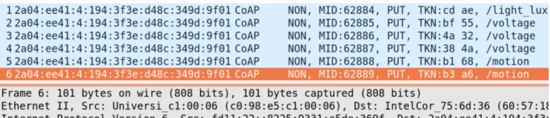
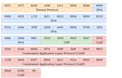
sudo tcpdump -i eth0 -vv udp port 5683 -X -n -w /tmp/packet dump.pcap As can be seen in the command above, the packets arriving at standard CoAP port 5683 are being stored as a pcap file, called packet dump.pcap. This file, containing all the received packets, was then analyzed, using Wireshark1. Fig- ure 4.3 shows the general structure of the packets coming from the Permamote.
The aim is not to go into detail with regards to the headers of the different layer-protocols. But rather a general overview should be gained, of how packets coming from the Permamote are structured, especially with respect to its pay- load. Nevertheless, for the sake of completeness, in Figure 4.4 the packet’s total content is split with respect to the protocol to which each fragment belongs to, whereas Figure 4.5 specifically shows the CoAP’s content in detail. Be aware that data is displayed in hexadecimal notation, for better readability compared to bit representation.
With respect to the people detection application, four important fragment of information are within the payload of each packet. As more than one Permamote is active, each of them must be uniquely identified. This allows to associate packet-content to the right Permamote. The easiest way to get a unique ID for each Permamote is by extracting its MAC address. Secondly, the type of content included inside the packet needs to be determined. The type of content can for example be motion from the PIR-sensor, light intensity from the light sensor, or also voltage reading of the different energy sources. To distinguish between
1https://www.wireshark.org/
4. Implementation 26
Figure 4.3: Captured packet, containing different layer’s headers, as well as CoAP’s payload, called Data
these, every packet includes a URI-path, identifying the type of data which the packet contains. As third information, the timestamp relating to when exactly the sensor has taken the measurement has to be extracted. And as a last peace of information, the actual value measured needs to be extracted. Refer to Figure 4.5, which shows in detail where in the packet’s payload these just mentioned information can be found.
4.4.2 Multi-Threading
Let us now take a closer look of how the packet post-processor is implemented on the host computer. The implemented packet analyzer executes three im- portant tasks in parallel. Figure 4.6 gives an overview about the parallelized Threads and the different storages used. Refer to the figure at any time during this section as an accompanying illustration. Each Thread is explained in the following.
Server/Parser Thread
First of all, incoming CoAP packets are being captured and parsed by a server, listening on port 5683. This server Thread needs to be able to capture packets at any time. This is important, because dropped packets are lost, as the UDP protocol without any acknowledgement is used. At the same time, this Thread parses the packets to extract the information explained in Section 4.4.1. After parsing the packets, the server simply stores the packets to a queue, which is the end of its duty with respect to the received packet.
4. Implementation 27
Figure 4.4: Captured packet, split according the the protocol the data belongs to
Figure 4.5: CoAP’s packet content is being analysed in more detail, showing the important fragments with respect to the people detection application
Post-processing Thread
This Thread reads packets from the queue and post-processes their content.
The reason for handing this procedure to a second process, instead for the server to handle the task, is that this is not time-critical. The amount of time for the server to be occupied with a single packet should be kept as short as possible, in order to be uncommitted for future packets to arrive. This Thread handles a packet read from the queue in the following way:
1. Determine the URI-path of the packet, to decide on the storage to use.
2. If it is a LUX or voltage packet, the following happens: The ID is read and afterwards the packet replaces the currently stored packet with the same ID in the URI’s active storage. The currently stored packet is moved to
4. Implementation 28 the archive, as its information is now outdated.
3. If it is a motion packet, the process only reads the ID and appends the packet to the correct active motion storage. A third process is then re- sponsible to handle the motion packets further.
Motion-handling Thread
The reason for using an additional Thread to handle the motion events, is to provide flexibility to easily adjust the motion handling as a user. This allows a user to integrate more robustness into the people counter. Also, the interaction of the motion packets coming from the two different Permamotes brings a higher degree of complexity. While the light intensity, as well as the voltage level is only interesting with respect to the device from which it originates, the information about motion events of the different Permamotes have to be handled together, to relate motion to people counting in our implementation. This motivates this task to be handled in an additional Thread. Every time the motion handling Thread is called, the following steps are processed:
1. The stored packet’s timestamp of the motion storage ID 1 are compared to stored packet’s timestamp of the motion storage ID 2. If two packets have been found, with their timestamps lying within a certain range to each other, these two packets are removed from the storage and registered as a person entering or leaving the controlled environment through the gate. A counter either counts an additional person inside the controlled environment, or a person is being removed. This decision is based upon which ID’s timestamp has the higher value. The removed packets are stored as one event inside of the motion archive.
2. After having removed all paired motions in the first step, the remaining packets in the active motion storage, which have for sure only occurred on one side, need to be moved to the archive as well. If this step would not be performed, the active storages would grow bigger over time, which would increase the amount of time to find pairs. Without a question, if one or both of the permamotes operate in low-power mode (Section 4.2), it is possible for them not having sent all packets yet. Therefore one cannot simply trash all remaining packets in the storage, as pairs to some of the packets could still be received in the future. A simple procedure is followed to remove the correct packets: Take the packet with the biggest timestamp of both IDs.
Archive all packets of the ID list, that has the smaller biggest timestamp.
We can do this step, because we already have all the information from the sensors before their latest timestamps. Therefore, all pairs of the ID with smaller timestamp have already been found. Of the list with the larger
4. Implementation 29 timestamp, archive only the packets that have timestamps smaller then the largest one of the other list.
Figure 4.6: Multi-Thread
Robustness Implementation Above, the implementation of the motion han- dler was explained. However, this is a very simple implementation and shows room for improvement to make the system more robust. As mentioned, the mo- tion handler’s Thread provides the flexibility to optimize the way the motion is handled. After implementing the version above, we have decided to implement a more robust motion handler. This implementation is meant to show one way of improving the system within this Thread. It is up to the user to come up with an even more robust version, optimized to his needs and system setup. The robust motion handler implementation aims to correct two common errors happening when using the simple motion handler. Firstly, the robust implementation cor- rects some miscounts. If the system shows zero people or a negative amount of people present, the robust implementation tries to correct this. The Thread is implemented such that it only corrects this error, if it is certain that some- body is inside of the room. ‘Somebody inside’ is defined, if at least two motions within a user-define time span have occurred in the monitored area. Secondly, the implementation aims to correct counts of people, even though nobody has left or entered the room. This mistake is common if in both sensor range a per- son is standing. This triggers a lot of motion events on both sensors with their time stamps being within close margin. The normal system then often count somebody as leaving or entering the room. The robust implementation reduces this error as follows: Let us assume motion of the sensor inside of the monitored room to be motion of type A, while motion of the sensor outside is of type B. If
4. Implementation 30 a motion pattern of kind ABA or BAB occurs, normally the first two motions of this triple would be matched as somebody entering or leaving the room. In the robust implementation, if all time stamps of this triple are within a certain range to each other, the first two motions are not considered as a person leaving or entering the room. This improves the robustness, if it is more likely that two people are within range instead of entering of leaving the room, in case of such a triple motion event occurring. To forestall, this increased the accuracy of the system, as will be explained in the results, in Chapter 5.
After having discussed the three main Threads running in parallel, it is to be mentioned that a fourth small co-process is also running at the same time. This fourth process has the simple task of storing all archived data from time to time to CSV-files. This allows to store the data in a safe way, as well as using them within some other program - or to analyze them further later-on.
4.5 GUI Interface - Dash
A GUI interface is implemented to accompany the people detection application with a visualization of the gathered data. The GUI interface was built using the Dash web application framework, based on the plotly library of Python2. It can be found as a Python script, called gui people detector.py. The interface is indirectly connected to the packet analyzer by reading its produced CSV-files and displays the gathered results inside the GUI, as as shown in Figure 4.7 shows. The program can be run in parallel to the packet analyzer and refreshed manually, using the ’Update all Graphs’-button. This allows to visualize the data ’live’, meaning that always the newest available events that have occurred can be monitored.
2https://dash.plotly.com/introduction
4. Implementation 31
Figure 4.7: GUI-interface
Chapter 5
Results
This chapter presents a verification of the final system of the people detec- tion implementation. The goal of the results are to show that the implemented application works as a complete system. While this was the main goal, at the same time the implementation was tested for how well it generally performs. In Section 5.2, additional tests that were conducted are shown, aiming to find out the current limitations of the implementation, that can be improved in future work.
5.1 Testing Scenarios
Verification Setup
For verifying the application, different scenarios are tested as shown in Figure 5.1. The scenarios present different detection periods of the Permamote. The detection time defines the period between the sensor triggered by some motion, until it reenters its low-power sense state. In the low-power sense state, the sensor can be triggered at any time by some motion occurring. This implies, that the maximum number of people that can be counted by the system has an upper limit given by the detection period per person. For each scenario, three test cases have been conducted. The test cases vary the time interval between the persons entering and leaving the room one after another, as can be seen in the middle of Figure 5.1. For each test case, three test persons are entering and leaving the room, with the respective time interval between each other. The aim is to find a lower bound of the detect period, for which the system can still distinguish between the different test persons.
Results
The different scenarios, together with the different test cases per scenario are classified for their reliability of correctly counting the number of test persons.
32
![Figure 3.2: Opposite poled IR-elements placed in an alternated way, in order to detect motion in 2D [1]](https://thumb-eu.123doks.com/thumbv2/1library_info/4648498.1608176/23.892.349.579.184.376/figure-opposite-poled-elements-placed-alternated-detect-motion.webp)
![Figure 3.3: Fine-grained placement of IR-elements within a PIR-sensor, for higher detection accuracy withing the detection area [1]](https://thumb-eu.123doks.com/thumbv2/1library_info/4648498.1608176/24.892.243.680.189.525/figure-grained-placement-elements-detection-accuracy-withing-detection.webp)