Virtual Reality
VR Displays & Stereo Rendering
G. Zachmann
University of Bremen, Germany
cgvr.cs.uni-bremen.de
The Kinds of VR Displays
§ Autostereo Monitor
§ Head-Mounted Displays (HMDs)
§ Head-Coupled Displays (HCDs)
§ Immersive projection displays (IPDs)
§ "Powerwall"
§ Workbench
§ Cave
§ "Exotic" displays:
§ Retinal displays
§ Holographic displays
§ ...
Stereo Monitor (mostly Autostereo)
§ Sometimes called "Fishtank VR"
§ Advantages:
§ Inexpensive
§ Resolution up to 1900 x 1600
§ Well accepted by users
§ No special requirements on the environment/setting
§ Some 3D capabilities
§ Disadvantages:
§ Small Field-of-View (FoV)
§ No immersion
§ Very limited working volume
§ "Stereo frame violation" is very common
§ Interesting things you
can do with a simple
monitor: the "Reachin-
Idea"
§ The problem with a small FoV:
there is no immersion!
Head-Mounted Diplays (HMD)
§ First "true" VR display
§ Technologies / characteristics:
§ HMDs using LCDs (sometimes CRTs)
§ Weight:
- Small FoV → lightweight; large FoV → heavy
§ Advantages:
§ Kind of "surround display"
§ Very good immersion
§ No "stereo frame violation"
§ Large working volume
§ Low-end models are inexpensive
§ Almost no special requirements on the
working environment
§ Disadvantages:
§ Uncomfortable when used for a prolonged time ("invasive interface")
§ Distortions
§ Real environment is shut off (good for immersion, bad for collaboration and self-embodiment)
§ Manipulation of real controls is difficult (e.g., in mockup of cockpit)
§ Every participant needs an HMD (bad: expensive, good: everybody has correct perspective in VE)
§ Actually, HMDs hve been invented a long time before "VR"
200
o60
o120
oHuman FoV
VR4
Datavisor Powerwall
Bell Helicopter, 1967
Head Coupled Displays (HCD)
§ HCD = HMD mounted on a
"boom"
§ Advantage of HCDs over HMDs:
§ Possible to quickly "take the display off" for a moment; or
users can just take a "quick peek"
into the VE
§ Low weight on the head
§ Extremely good tracking comes built-in
§ Disadvantages compared to HMDs:
§ Smaller working volume
§ One hand is always occupied
§ Inertia
à Failed to gain market share
Immersive Projection Displays / Technology (IPD / IPT)
§ Idea is (somewhat) similar to cinema theaters
§ Setup: 1–6 walls on which VE is projected
§ Powerwall = 1 wall (e.g., 3x6 meters)
§ Workbench = 1 horizontal display surface (table)
§ Holobench, L-Shape = 2 display surfaces, 1 vertical, 1 horizontal
§ Cave = 3–6 walls
Powerwall
Powerwall with back projection Powerwall with front projection,
(problems with that: edge blending, hot spots)
§ "HeyeWall", Darmstadt:
§ 24 tiles, 48 PCs
§ Total resolution: 18 Mio
pixels (6144 x 3072) in
stereo
Example Application: Virtual Conference Room
Result: 1 shared workspace, by way of coherently adjoining
"desktop IPD"
Workbench, L-Shape, etc.
Workbench
Holobench
Principle of the workbench Tilting "workbench"
Cave
3-wall cave
Schematic of the arrangement of the mirrors
5-wall cave, FhG-IGD, Darmstadt
6-wall cave, Alborg, DK
RealityDeck - Immersive Giga-Pixel Display
§ Developed at Stony Brook U, New York
§ 308x 30" LCD displays
§ 2560 x 1600 resolution per display
§ 1.2+ billion pixels of resolution in total
§ 40'x30'x11' physical
dimensions
§ 85 dual quad- core, dual-GPU cluster nodes
http://www.cs.stonybrook.edu/~realitydeck/
Curved Screens
Curved Screen made out of 3D-TVs
§ Idea: construct the walls of a Cave out of a (small) number of 3D TVs
§ Advantage: reconfigurable relatively easily (just put the walls on
wheels)
Personal Domes
§ Example: Wii + Dome + MacBook Pro
Source: Paul Bourke, University of Western Australia, http://local.wasp.uwa.edu.au/~pbourke/
§ A modern "Sensorama":
Immersa-Dome from Aardvark Applications
VirtuSphere
www.virtusphere.com
Studie
Advantages and Disadvantages of IPDs
§ Advantages:
§ Large resolution (currently up to ca. 1600 x 1280 per tile)
§ Large field-of-view
§ "Non-invasive"
§ No isolation of the real world
§ (Can accomodate Several Users)
§ Cave: turning the head results in small changes of the images à problem of latency is reduced / not so prominent
§ Disadvantages:
§ Size
§ Price (lots of projectors, lots of graphics cards)
§ Precision, calibration
§ Potentially "stereoscopic violation"
§ Correct view only for one viewer (unless a massive amount of hardware is used)
Retina Displays (retinal displays)
§ Idea:
§ Use the human retina as the display surface (all images from the outer world end up there anyway)
§ Use a laser to write the image by scanlines into the eye
§ Advantages:
§ Can be miniaturized (potentially)
§ High contrasts, high brightness
§ Good for see-through displays
§ Small power consumption
Video Source
Drive Electronics
Laser Intensity Modulator
Beam Scanning
Optical
Projection
Retinal display
Design study
Holographic / Volumetric Displays
§ Real 3-dimensional displays
§ Advantages:
§ Provide correct perspective/view from every angle!
§ Coherence between accomodation and convergence
§ Depth of field (Tiefen(un-)schärfe)
§ Holographic displays: algorithmic computation of holograms
§ Problems:
§ Staggering amount of computational work
§ Colors
§ Volumetric displays: voxel are projected into a volume (as opposed to a surface)
§ Problems:
§ Size of data (e.g. 100 mega-voxels = 1000x1000x100 display resolution)
§ Occlusions?
§ Example volumetric display:
§ 198 x 768 x 768 ≈ 100 million voxels
§ Frame rate: 20 Hz
Unusual Display Surfaces
§ Fog ("fog screen"):
§ Laminar, non-turbulent air flow
§ Water droplets are "sandwiched"
within the air flow
FogScreen
Olwal et al.: Consigalo: Multi-user, Face-to-face Interaction on an Immaterial Display
§ "Everywhere displays":
The History of Stereo Images
§ Euklid (4th century BC)
§ Sir Charles Wheatstone (1838 )
§ 1860: 1 million Stereoscopes sold
§ 1950-ies:
■ Today
(demo):
How to Project Stereo with only one Display Surface?
§ Need some kind of Multiplexing
1. Temporal Multiplexing ("active stereo"):
§ Typically 1 projector (e.g. monitor)
§ Project/render alternatingly left/right image
§ Synchronously, switch left/right glass of shutter glasses to pass-through
§ Shutter glasses run with 120 Hz → 60 Hz framerate
2. Multiplexing by polarization ("passive stereo"):
§ Usually 2 projectors displaying on same surface
§ Project left/right simultaneously but with different Polarization of the light
§ Polarization glasses let only left/right images pass,
resp.
§ Kinds of polarization:
1. Linear polarization:
- Any direction perpendicular to direction of travel of light
2. Circular polarization:
- Left-handed / right-handed polarization
Demo
http://www.colorado.edu/physics/2000/applets/polarization.html
"Color Multiplexing"
§ Simple version: Anaglyph stereo (red-green stereo)
§ Generalization ("Infitec", Dolby3D, spectral comb filter, wavelength multiplex):
§ Each of the primary colors must pass through a narrow band pass filter
§ Left & right eye get filters with interleaving band passes
§ Problem:
§ Color fidelity
Filter 1
The Problem of Multiple User and a Single IPD
§ Problem with a single-
tracked projection (stereo or mono): only the
viewpoint of the tracked users is correct, only she will see a correct image!
§ Example:
Image's perspective is correct for the user
Image's perspective is correct for the (real) camera
Correct (Stereo-)Projection for Multiple Users
§ Probably only possible for a small number of users
§ Temporally multiplexed:
§ Framerate for multi-user stereo = Framerate for mono * 2 . #User
§ Infitec for several users:
§ Each user gets glasses with slightly shifted comb filters
§ With n users we need 2n different comb filters → extremely narrow bands
§ Spatially multiplexed
§ Combination of the above
Spatial Multiplexing
§ Proj. surface is partitioned among users
§ Consequence: interdependence between
§ Size of the view frustum
§ Working volume of users
§ D & radius of hole
§ Example:
§ Illusion Hole
IllusionHole @ Siggraph 2001
G. Zachmann Virtual Reality & Simulation WS 5 November 2012 Displays and Stereo Rendering 45
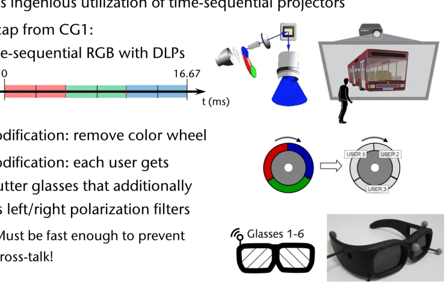
Stereo for 6 Users [2011]
§ Combination of active and passive stereo,
plus ingenious utilization of time-sequential projectors
§ Recap from CG1:
time-sequential RGB with DLPs
1. Modification: remove color wheel 2. Modification: each user gets
shutter glasses that additionally has left/right polarization filters
§ Must be fast enough to prevent cross-talk!
0 16.67
t (ms)
3D displays. Their systems use modified DLP projectors to project fast time-sequential images onto a rotating anisotropic projection surface. Both systems achieve about one degree of angular resolu- tion and support a 180 and 360 degree field of view, respectively.
[Jones et al. 2009a] reported on a further refined prototype of such a system and showed its use in a very convincing real-time one-to- many teleconferencing application [Jones et al. 2009b]. Due to the use of a single projector, the bandwidth of these systems is limited, which results in a small color depth of one bit color or even only black and white depending on the used DLP projector type. In ad- dition, such a system is difficult to scale to a larger size due to the rotating display surface.
The research surrounding collaborative virtual environments (CVEs) has mostly focused on distributed collaboration (e.g. [Ben- ford et al. 2001] reviews the history of CVEs). [Otto et al. 2006]
and [Wolff et al. 2007] provided a solid analysis of the require- ments for supporting closely coupled collaborative tasks in a shared virtual workspace for non-co-located users, which also apply to a certain extent to co-located collaboration. However, there is lim- ited work on co-located collaboration in projection-based multi- user virtual reality. The original two-user Responsive Workbench work [Agrawala et al. 1997] suggested the use of specialized views, which were used to provide different information to each user, as in a teacher-student scenario. [Riege et al. 2006] suggested the use of a bent pickray to visualize the constraints that are involved when two users are jointly manipulating an object with six degrees of freedom. [d’Angelo et al. 2008] showed that stereoscopic display in combination with collaborative manipulation improve task per- formance and are clearly preferred in a complex assembly task in- volving two users. [Argelaguet et al. 2010] demonstrated the use of specialized views to reduce the problem of interpersonal occlusion.
All these approaches consider only two collaborating users and fo- cus on joint manipulation. It is not clear how these approaches scale to more users.
[Bowman et al. 2005] provide an overview and introduce a taxon- omy for the large variety of navigation techniques for virtual envi- ronments. However, the problem of navigating multiple co-located users with individual views through a shared virtual world has not yet been addressed. Group navigation as it is defined here – mov- ing multiple people simultaneously through a virtual environment – is a new problem that is closely linked to the introduction of stereoscopic multi-viewer systems. Augmented group navigation techniques to mitigate associated issues are orthogonal to general single-user navigation techniques. In our setup each head-tracked person can independently walk in front of the display, but apart from that, does not independently travel within the environment since otherwise the group would no longer share a consistent virtual space.
3 Synchronized 12-View Projector Array
Our goal was to build a fast time-sequential full color DLP-based system which also exploits polarization. Our approach is based on the following ideas:
• Color wheel DLP projectors project the different primary col- ors as fast time-sequential images. There are various color wheel versions; we assume a basic three-segment color wheel consisting of three color filters, one in each primary color:
red, green and blue. If the color wheel is removed, we can project three monochrome time-sequential views (Figure 2) instead of the different primary colors of a single view. By using three projectors and equipping each projector with a pri- mary color filter, we regain full color images for three views.
Figure 2:A three-segment color wheel. We display individual im- ages for three eyes instead of time-sequential colors.
• Most DLP projectors rotate the color wheel at least twice per video frame and are thus effectively running at 120Hz while 60Hz input is provided. However, at the time of our devel- opment, a 1920x1200 pixels resolution projector was not yet available, which would accept a 120Hz stereo signal. Thus we had to extend an existing projector to process a 120Hz image stream or to interleave two 60Hz streams. This way we could project six different views at 360Hz (three views times two rotations times 60Hz).
• Polarization can be effectively used in combination with shut- tering to double the number of views, thus allowing 12 views to be achieved using two times three projectors.
Such a system maintains the brightness of a single user active stereo system since we are using six projectors for six users. In addition, we retain full color depth, full resolution (1920x1200) and a 60Hz refresh rate. Figure 3 shows an overview of our setup.
Figure 3:The projector array is driven by a single computer. Three synchronized NVIDIA Quadro Plex 7000 graphics systems are con- nected to the host computer via separate PCIe interfaces. Each Quadro Plex consists of two graphics cards with two DVI outputs each. It produces the left and right eye images for two users. Sets of three DVI outputs carrying the images for three eyes are connected to the video multiplexers (muxer), which rebin the image streams by color and send them to the respective projectors. The left three projectors display the left eye images for the six users, while the right three projectors display the right eye images. The two sets of projectors emit differently polarized light which matches the polar- ization of the users’ left and right eye shutters. External synchro- nization is provided to the projectors and to the radio-controlled shutter glasses.
C1x6: A Stereoscopic Six-User Display for Co-located Collaboration in Shared Virtual Environments • 188:3
ACM Transactions on Graphics, Vol. 30, No. 6, Article 188, Publication date: December 2011.
sive than standard liquid crystal (LC) shutters and they are very fragile. FLCs are also designed to work with symmetric open/close timings, which is not the case in our setup.
As an alternative to FLCs, we built our shutter glasses based on a novel double-cell shutter design, which consists of two layers of differently configured regular LC shutters. The first layer is a reg- ularly cross-polarized LC shutter (normally white (NW)), which is transparent if no voltage is applied. The second layer has equally oriented polarization filters on both sides and thus it is opaque (nor- mally black (NB)) if no voltage is applied. This combination of shutters functions so that the NB shutter opens quickly while the NW shutter closes quickly. These shutters are ideally suited for an asymmetric use case: our shutters need to be open for only1/360th of a second and closed for5/360thof a second. During the longer closing time, both shutters relax one after the other: first, the NB shutter closes fully and then the NW shutter opens completely (Fig- ure 5). In addition, using a stack of two shutters improves the con- trast ratio, an important property in the context of our system.
Figure 5:Illustration of the double shutter functionality (top), the electrical shutter driving pattern (middle) and the time slots for each user (bottom). At 60Hz a 16.67ms time frame is divided into six adjacent user time slots of equal length. The diagram shows the timings of the double cell shutter of user 4, who receives an image during the fourth slot lasting from T2=8.34ms to T4=11.12ms. The NW shutter is switched off at T1about 2ms before T2to ensure its relaxation and thus maximum light transmission at the beginning of the following opening period. The NB shutter is still blocking light during this NW relaxation phase and immediately opens when the voltage is applied at the beginning of the 4th time slot (T2). At the end of the opening period of 2.78ms (T4) the NW shutter is immedi- ately blocking the light transmission as the voltage is applied. The NB shutter is switched off for relaxation slightly before (T3=11ms).
In a six-user stereo-projection system each individual shutter must blank 11 of 12 displayed images. For a left eye shutter of a particu- lar user three distinct cases can be considered (similarly for a right eye shutter):
1. The user’s right eye image is separated by polarization.
2. The left eye images of the other 5 users are blocked by the shutter operation.
3. The right eye images of the other 5 users are blocked by po- larization and shuttering.
The first case contributes only the relatively low crosstalk of stan- dard polarization-based systems. The second case is addressed by our new double-cell shutter design, which provides fast switching times and high contrast to avoid crosstalk. In our setup the shut- ters in closed state must block five times more light as compared to the case of active stereo displays. Double-cell shutters help with
Figure 6: Our custom shutter glasses consist of two double cell shutters, a Zigbee radio module, a rechargeable lithium-polymer battery and the shutter driving circuit. The housing also con- tains multiple threaded holes for assembling different IR-reflective marker configurations.
this requirement since the total contrast ratio is the product of the contrast ratios of the NW cell and the NB cell. The third case con- tributes at least one order of magnitude less crosstalk than the other two cases since the light is blocked by shuttering and polarization.
We designed our wireless shutter glasses (Figure 6) such that their principal state can be controlled from the application, independent of the basic clocking. The communication to the shutter glass con- troller is realized by using the µracoli implementation [URACOLI 2011] of the two lower levels of the IEEE 802.15.4 protocol stack for wireless personal area networks (which form the basis of the Zigbee protocol). There are two different aspects that can be pro- grammed:
• The general assignment to one or more of the six-user time slots. This control can be used to implement a VIP (Very Important Person) mode by assigning two or more time slots to a single person. We often have the case that the system is used by less than six individuals and thus we use this control to increase the brightness by assigning more than one time slot to one or more users.
• A transition from shutter mode to full-open mode and vice versa. In regular operation the shutters are open for only 1/6thof the time and thus everything but the display is per- ceived as quite dark. However, if six people are in front of the display discussing various aspects of their application, it quite often happens that they look at each other or do not look at the display at all. They may even move to a whiteboard to continue discussion. In these cases we open the glasses and turn off the shutter mode using simple heuristics based on the head tracking information.
There are many other uses for application-controlled shutter glasses. Particularly in multi-display environments (e.g. [Pirch- heim et al. 2009], [Kitamura et al. 2009]), where users interact with a variety of displays, shutters need to sync to the currently faced display and should be turned off if it is a 2D display or only 2D content is presented.
C1x6: A Stereoscopic Six-User Display for Co-located Collaboration in Shared Virtual Environments • 188:5
The Hardware in Principle
§ 6 stereo video streams are generated by 6 graphics cards in 1 PC
§ Distribution of the video streams to the projectors via multiplexers
Quadro Plex GFX Card GFX Card
Quadro Plex GFX Card GFX Card
Quadro Plex GFX Card GFX Card
Gen- lock
Genlock PCIe
Host PC
Muxer
RGB
Muxer
6x Rot @ RGB 360 Hz
6x Rot @ 360 Hz
Warning: in the real world, there are no such projectors available!
(capable of 360 Hz inputs)
§ Timing:
§ Video:
User 1 User 2 User 3 User 4 User 5 User 6