Ultra Low-Power MAC Layer Wake-Up-Frame Scheme for Low-Cost and Low-Traffic
Wireless Sensor Networks
Der Fakult¨at f¨ur Elektrotechnik und Informationstechnik der Universit¨at Dortmund vorgelegte
Dissertation
zur Erlangung des akademischen Grades Doktor der Ingenieurwissenschaften
von Xiaolei Shi
geboren am 26. Juli 1974 in Shanghai
1. Gutachter: Prof. Dr.-Ing. Uwe Schwiegelshohn 2. Gutachter: Prof. Dr.-Ing. R¨udiger Kays Dekan: Prof. Dr.-Ing. Edmund Handschin
Tag der Einreiching: 1 Juni 2005 Tag der Pr¨ufung: 14 Dezember 2005 Stand von: 4 M¨arz 2006
To my wife Lan Chen and my daughter Wenyue Shi.
Abstract
Wireless sensor networks, as a key enabling technology of Ubiquitous Computing, have been a booming research topic in the recent years. Upon designing a low-cost wireless sensor device, power consumption is one of the most important issues, because cheap batteries are normally the power suppliers. Since the RF transceiver is one of the biggest power consumers in such a sensor device, enabling the RF transceiver to sleep as much as possible is the preferred method to save power, which is normally realized by MAC layer duty cycle scheduling.
This dissertation proposes a MAC layer wake-up-frame scheme to wake up an RF trans- ceiver on-demand to minimize the standby waiting time in receive mode to save power.
Analytical and simulation results show that, for a low-traffic wireless sensor network, this scheme gives significant system battery lifetime gain compared to the traditional methods.
Furthermore, the combination of the wake-up-frame scheme and a complementary low- power MAC protocol is discussed. Analytical computation and simulation prove that the combined scheme achieves a further optimized solution in the sense of power-saving, while other important system parameters, such as response time and channel efficiency, are lim- ited to a reasonable range.
Keywords:low-power MAC, wireless sensor network, duty cycle scheduling.
Acknowledgements
I would like to thank Dr. Guido Stromberg for his many suggestions and constant sup- port during this research. I am also thankful to Prof. Uwe Schwiegelshohn for his kind supervision.
I would also thank Dr. Werner Weber, the head of the Emerging Technologies Labora- tory in Corporate Research at Infineon Technologies, for his kind leadership, and my other colleagues Yvonne Gsottberger, Thomas Sturm, Jan Dienstuhl, Daniel Bichler, Christl Lauterbach, Stephan Jung, Rupert Glaser, Markus Schnell, Eike Ruttkowski, Bernhard Knoll, Christoph Braun, Domnic Savio, and Martin Verbeek for their support and friend- ship.
I would like to also mention Ms. Chong Cai for the contribution of her master thesis, and Mr. Mario Hernan Castaneda Garcia for his excellent job as a working student.
Of course, I am grateful to my wife for her love and care, and to my daughter (born on 2004.11.04), who brings me a lot of happiness and takes me also a large amount of time. :) I would also thank my mother and my parents-in-law. They helped me a lot to take care of the baby.
Finally, I wish to thank the following: Edwin Naroska, Holger Linde, Peter Schramm, Peter Resch, and J¨org Platte.
Xiaolei Shi June 2005
Table of Contents
Abstract iii
Acknowledgements v
Table of Contents vii
List of Tables xi
List of Figures xiii
Glossary i
1 Introduction 1
2 Wireless Sensor Networks 5
2.1 Ubiquitous Computing . . . 5
2.2 Wireless Sensor Networks . . . 6
2.3 Sindrion Basic Concept . . . 7
3 Power Consumption Issue in WSNs 11 3.1 Introduction of Power Saving Methods . . . 11
3.1.1 Low-Power Circuit Design . . . 11
3.1.2 Fewer Transmission . . . 12
3.1.3 More Sleep . . . 13
3.2 Power Saving Methods for Sindrion . . . 13
3.3 Available Low-Power MAC Layer Duty Cycle Scheduling Schemes . . . 15
3.3.1 IEEE 802.15.4 LR-WPAN MAC Layer . . . 16
3.3.2 Preamble Sampling . . . 17
3.3.3 WiseMAC . . . 19
3.4 Possibilities for Further Improvement . . . 20
4 Ultra Low Power MAC Layer Wake-Up-Frame Scheme 23 4.1 Multiple Power Domain Hardware Architecture . . . 23
4.2 The Wake-Up-Frame Scheme Description . . . 25
4.2.1 The Wake-Up-Preamble Scheme . . . 25
4.2.2 The Wake-Up-Frame Scheme . . . 27
4.3 The Wake-Up-Frame Scheme Analysis. . . 29
4.4 Wake-Up-Frame and WiseMAC Combination . . . 30
5 Analytical Computation 31 5.1 Computation Principle . . . 32
5.2 Computation Results . . . 35
5.2.1 Power Consumption and Battery Lifetime . . . 35
5.2.2 Channel Occupation . . . 43
5.2.3 Response Time . . . 46
5.2.4 Others. . . 47
5.3 Analytical Conclusion . . . 50
6 Simulation Models 53 6.1 Simulation Framework . . . 53
6.2 Protocol Layers and Models . . . 55
6.2.1 Indoor Channel Model . . . 55
6.2.2 Physical Layer . . . 67
6.2.3 FPGA Module . . . 68
6.2.4 MAC Layer . . . 69
6.2.5 Application Layer . . . 73
7 Simulation Results and Analysis 75
7.1 Downlink Traffic . . . 75
7.1.1 Battery Lifetime . . . 75
7.1.2 Channel Occupation . . . 78
7.1.3 Response Time . . . 79
7.2 Uplink and Downlink Traffic . . . 80
7.2.1 Battery Lifetime . . . 80
7.2.2 Channel Occupation . . . 83
7.2.3 Response Time . . . 84
8 Conclusion 87 A Analytical Computation Details 89 A.1 The IEEE 802.15.4 MAC . . . 90
A.1.1 Unicast . . . 91
A.1.2 Broadcast . . . 91
A.2 The WUP Scheme. . . 92
A.2.1 Unicast . . . 93
A.2.2 Broadcast . . . 93
A.3 The Rep Scheme . . . 94
A.3.1 Unicast . . . 95
A.3.2 Broadcast . . . 96
A.4 The WUF Scheme. . . 96
A.4.1 Unicast . . . 96
A.4.2 Broadcast . . . 98
A.5 The WiseMAC+WUP Scheme . . . 98
A.5.1 Unicast . . . 98
A.5.2 Broadcast . . . 104
A.6 The WiseMAC+Rep Scheme . . . 104
A.6.1 Unicast . . . 104
A.6.2 Broadcast . . . 111
A.7 The WiseMAC+WUF Scheme . . . 111
A.7.1 Unicast . . . 111
A.7.2 Broadcast . . . 118
A.8 The Ideal Preamble Sampling. . . 118
A.8.1 Unicast . . . 118
A.8.2 Broadcast . . . 119
A.9 DRD vs. RSSI. . . 119
B Basic Parameters 121 C Frame Structure 125 C.1 Frame Structure . . . 125
C.2 Fields Definition . . . 127
C.2.1 MAC . . . 127
C.2.2 FPGA . . . 128
Bibliography 129
List of Tables
3.1 Power Consumption of the Components . . . 14 B.1 Basic Parameters of the Sindrion System . . . 121
List of Figures
2.1 Sindrion System . . . 8
3.1 The IEEE 802.15.4 MAC Superframe Structure . . . 16
3.2 The Preamble Sampling Basic Idea . . . 18
3.3 The WiseMAC Basic Idea . . . 20
3.4 The Data Repetition Basic Idea . . . 20
4.1 The Sindrion Hardware Architecture . . . 24
4.2 The Wake-Up-Preamble Scheme . . . 26
4.3 The Wake-Up-Frame Scheme. . . 27
5.1 The WiseMAC+WUP Detail . . . 33
5.2 Battery Lifetime of Preamble Sampling and IEEE 802.15.4 MAC (No Traffic, Analytical) . . . 36
5.3 Battery Lifetime of all the Schemes (10 slaves, Unicast, Downlink, Analytical) . . . 37
5.4 Battery Lifetime of all the Schemes (100 slaves, Unicast, Downlink, Analytical) . . . 38
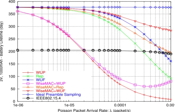
5.5 Battery Lifetime of all the Schemes (1000 slaves, Unicast, Downlink, Analytical) . . . 40
5.6 Scalability of all the Schemes (λ= 0.001, Unicast, Downlink, Analytical) . . . 41
5.7 Frame Length of all the Schemes (λ= 0.001, Unicast, Downlink, Analytical) . . . 42
5.8 Battery Lifetime of all the Schemes
(Broadcast, Downlink, Analytical) . . . 43
5.9 Channel Occupation of all the Schemes (10 slaves, Unicast, Downlink, Analytical) . . . 44
5.10 Channel Occupation of all the Schemes (100 slaves, Unicast, Downlink, Analytical) . . . 45
5.11 Channel Occupation of all the Schemes (1000 slaves, Unicast, Downlink, Analytical) . . . 45
5.12 Response Time of all the Schemes (100 slaves, Unicast, Downlink, Analytical) . . . 46
5.13 RSSI vs. DRD (No Traffic, Analytical). . . 48
5.14 Battery Lifetime of WiseMAC+WUF (Data Compression, 100 Slaves, Unicast, Analytical) . . . 49
6.1 The Simulation Framework . . . 54
6.2 Pathloss PDF of SIRCIM (LOS) . . . 62
6.3 Pathloss PDF of SIRCIM (OBS) . . . 62
6.4 Pathloss vs. Distance (LOS) . . . 63
6.5 Pathloss vs. Distance (OBS) . . . 63
6.6 Pathloss PDF Comparison (LOS, 10m) . . . 64
6.7 Pathloss PDF Comparison (OBS, 10m). . . 64
6.8 Pathloss PDF Comparison (LOS, 20m) . . . 65
6.9 Pathloss PDF Comparison (OBS, 20m). . . 65
6.10 State Machine: RF Transceiver . . . 67
6.11 State Machine: FPGA. . . 68
6.12 State Machine: CSMA . . . 70
6.13 State Machine: IEEE 802.15.4 MAC Master . . . 71
6.14 State Machine: IEEE 802.15.4 MAC Slave. . . 72
7.1 Battery Lifetime of Basic Preamble Sampling Schemes (100 slaves, Unicast, Downlink, Simulation) . . . 76
7.2 Battery Lifetime of WiseMAC Schemes
(100 slaves, Unicast, Downlink, Simulation) . . . 77
7.3 Channel Occupation of All the Schemes (100 slaves, Unicast, Downlink, Simulation) . . . 78
7.4 Response Time of All the Schemes (100 slaves, Unicast, Downlink, Simulation) . . . 79
7.5 Battery Lifetime of Basic Preamble Sampling Schemes (100 slaves, Unicast, Up/Downlink, Simulation) . . . 80
7.6 Battery Lifetime of WiseMAC Schemes (100 slaves, Unicast, Up/Downlink, Simulation) . . . 82
7.7 Channel Occupation of All the Schemes (100 slaves, Unicast, Up/Downlink, Simulation) . . . 83
7.8 Response Time of All the Schemes (100 slaves, Unicast, Up/Downlink, Simulation) . . . 85
A.1 The IEEE802.15.4 MAC Detail. . . 90
A.2 The WUP Scheme Detail . . . 92
A.3 The Rep Scheme Detail . . . 94
A.4 The WUF Scheme Detail . . . 97
A.5 The WiseMAC+WUP Detail . . . 99
A.6 The WiseMAC+Rep Detail (Case 1) . . . 105
A.7 The WiseMAC+Rep Detail (Case 2) . . . 108
A.8 The WiseMAC+WUF Scheme Detail (Case 1) . . . 112
A.9 The WiseMAC+WUF Scheme Detail (Case 2) . . . 115
C.1 DATA Frame Structure . . . 125
C.2 ACK Frame Structure . . . 126
C.3 Short Wake-Up-Frame Structure . . . 126
Glossary
ACK Acknowledgement,3.3
ARQ Automatic Repeat reQuest,3.1 ASK Amplitude Shift Keying,3.2 BER Bit Error Rate,6.2
BI Beacon Interval in IEEE802.15.4 MAC protocol,3.3 BO Beacon Order in IEEE802.15.4 MAC protocol,3.3
CAP Contention Access Period in IEEE802.15.4 MAC protocol,3.3 CDF Cumulative Distribution Function,6.2
CFP Contention Free Period in IEEE802.15.4 MAC protocol,3.3 CRC Cyclic Redundancy Check,4.2
CSMA Carrier Sense Multiple Access,3.3
DRD Data Rate Detection function provided by TDA525x RF trans- ceiver,4.1
ECC Error Correction Coding,3.1
FPGA Field Programmable Gate Array,3.2 FSK Frequency Shift Keying,3.2
GTS Guaranteed Time Slot in IEEE802.15.4 MAC protocol,3.3 GUI Graphic User Interface,2.1
HARD Hard partitioned case in indoor wireless channel,6.2 ISI Inter-Symbol-Interference,6.2
ISM Industrial Scientific and Medical,3.2 LOS Line-Of-Sight,6.2
MAC Media Access Control,1.0 MANET Mobile Ad hoc NETwork,3.1 OBS OBStructed,6.2
OPEN Open plan case in indoor wireless channel,6.2 PDF Probability Density Function,6.2
PHY Physical layer,3.3 RF Radio Frequency,1.0
RSSI Received Signal Strength Indicator,3.3 RTC Real Time Clock,3.2
SIRCIM Simulation of Indoor Radio Channel IMpulse response,6.2 SNR Signal-to-Noise Ratio,6.2
SOFT Soft partitioned case in indoor wireless channel,6.2 SWUF Short Wake-Up-Frame,4.2
TDMA Time Division Multiple Access,3.4 UPnP Universal Plug and Play,2.3
WiseMAC WirelessSensorMAC,3.3 WiseNET WirelessSensorNETwork,2.2 WPAN Wireless Personal Area Network,3.3 WSN Wireless Sensor Network,2.2
WUF Wake-Up-Frame,4.0 WUP Wake-Up-Preamble,3.3
WUS Wake-Up-Signal, including WUP, WUF, and data repetition, 3.3
XML eXtensible Markup Language,2.3
Chapter 1 Introduction
Ubiquitous Computing has emerged as a hot research topic in the recent years. It inte- grates many computers and electronic devices into our living and working environments, automatically providing us with services according to our demands without attracting our attention. Ubiquitous Computing touches most aspects of the modern information and communication technologies from the applications, man-machine-interface, data models, semantic protocols, and security down to low-layer communication protocols and hardware design.
In Ubiquitous Computing, a large amount of devices integrated into the environment are small low-cost sensors, which collect various environmental information for the needs of the upper-layer applications. Since the sensors shall be unobtrusive, wireless commu- nication is the preferred solution to deliver these information from the low-cost sensors to central control computers or the like. For this reason, wireless sensor networks become a key enabling technology for Ubiquitous Computing.
One of the most important issues in a wireless sensor network is power consumption because the sensors are mostly powered by low-cost batteries and frequently changing the batteries for a large number of devices is obviously unacceptable. Therefore, many researchers are striving to reduce the power consumption from different aspects of the system design.
Among many possible power saving methods, minimizing the power consumed by the Radio Frequency (RF) transceiver is a very efficient way, because the RF transceiver is normally the most or one of the most power hungry components in such a small sensor
Chapter 1. Introduction
device. Traditionally, an RF transceiver has to keep staying in receive mode to wait for possible incoming packets. This is extremely inefficient for a low traffic wireless sensor network, since most of the energy is consumed by standby waiting instead of data com- munication. To this end, some approaches were proposed to enable the RF transceiver to sleep more by scheduling the duty cycle of the RF transceiver in the Media Access Control (MAC) layer.
This dissertation proposes an ultra low-power MAC layer protocol for low-cost and low-traffic wireless sensor networks, called the wake-up-frame scheme. It wakes up the RF transceiver on-demand by a wake-up-signal to minimize the standby waiting time in receive mode. Analytical and simulation results show that this scheme achieves a signifi- cant battery lifetime gain compared to the traditional schemes.
Furthermore, the wake-up-frame scheme and another low-power MAC protocol called WiseMAC are based on similar technology but are complementary to each other. Thus, the combination of these two schemes could generate an even better overall solution. To prove this idea, analytical computations and simulations have been conducted to compare the performance of the new combined scheme to the individual schemes. The results show that the combined scheme gives the lowest power consumption. Concurrently, other important system parameters, such as response time and channel efficiency, are also limited to a reasonable range.
This dissertation is organized as follows:
• Chapter 1provides the technical background of this dissertation by giving an intro- duction to Ubiquitous Computing, wireless sensor networks, and a so-called Sindrion system. The Sindrion system is a sensor network that bridges the small low-cost sen- sor devices to UPnP (Universal Plug and Play) networked high-end devices. Note that the proposed wake-up-frame scheme has been designed for the Sindrion system, but could also be applied to other wireless sensor networks.
• Chapter 2discusses the power consumption issue of wireless sensor networks and defines the problem to be solved by this dissertation. Some related work is intro- duced, and their benefits and disadvantages are discussed.
• Chapter 3 first describes the wake-up-frame scheme from hardware architecture to protocol details. Then, the combination of the wake-up-frame scheme and the
Chapter 1. Introduction
WiseMAC is discussed.
• Chapter 4conducts the analytical computation to estimate the gain and cost of the wake-up-frame scheme and the combined scheme.
• Chapter 5introduces the simulation models including the indoor wireless channel model, the communication protocols, and the application traffic model.
• Chapter 6illustrates and analyzes the simulation results.
• Chapter 7finally concludes the dissertation.
Chapter 2
Wireless Sensor Networks
2.1 Ubiquitous Computing
In 1991, Mark Weiser first addressed the concept of Ubiquitous Computing [1–3], which is named as the third wave in computing after the mainframes era and the personal computing era.
In Ubiquitous Computing, a large number of computers or other electronic devices with computing ability are pervasively embedded into the environment so that they become a part of the background, attracting no human attention any more. Unlike personal com- puters, Ubiquitous Computing is invisible to users, but it is everywhere and automatically provides services meeting user’s demands. That is the reason why it is also called Pervasive Computing or Invisible Computing.
Ubiquitous Computing touches almost every aspect of the modern silicon-based infor- mation and communication technology. Some examples are given as follows:
• Ubiquitous Computing needs huge efforts to create a new relationship between hu- mans and computers. It is not just a problem of man-machine-interface such as a friendly Graphic User Interface (GUI), but a property of the whole context of usage of the machine, which addresses many sophisticated technologies such as machine learning, data mining, and so on.
• Interacting with computers everywhere induces also severe privacy problem for an individual. Consequently, security technology will play a more and more important
Chapter 2. Wireless Sensor Networks 2.2. Wireless Sensor Networks
role in the third computing era.
• The distributed computers and devices need to communicate with each other to de- liver information, so wireless communication becomes a key enabling technology for Ubiquitous Computing.
• A large quantity of computers and devices means that the cost per device is an impor- tant issue, and invisibility means that minimization is also very important. Therefore, new semiconductor technologies are desired to lower the cost and shrink the size of the device.
Among these examples, the wireless communication, more specifically low-cost and low-power wireless sensor networks, is the scope addressed by this dissertation.
2.2 Wireless Sensor Networks
The devices in a Ubiquitous Computing environment comprise a large number of sensors.
They collect various environmental information such as temperature, humidity, brightness, and motion of objects to support applications like smart house or intelligent building. This information should be delivered to a central computer or device for further processing.
Since connecting such a large number of low-cost sensors by wires is in most cases infeasible, wireless communication becomes the only choice for the transportation of the sensed information. For this reason, Wireless Sensor Network (WSN) is attracting more and more research attention all over the world.
There are many restrictions on designing a WSN. First, sensor devices should be suffi- ciently small and cheap for being pervasively distributed into the background environment, which limits the complexity and computing capability of the device. As a result, only low- cost RF transceivers, inexpensive and small batteries, low-performance microcontrollers, little memory, and low-complexity algorithms can be used to meet the relatively high ap- plication requirements. This is the major challenge faced by the designers of WSNs.
So far, there are many projects addressing the WSN focusing on different aspects. Some examples are as follows.
Chapter 2. Wireless Sensor Networks 2.3. Sindrion Basic Concept
• PicoRadiois a famous WSN project conducted by wireless research center of the University of California in Berkeley [4]. This project includes almost all areas of WSNs: RF circuit design, networking, positioning, low-voltage digital design, an- tenna design, low-power analog design, energy scavenging, etc.
• WiseNET (Wireless Sensor NETwork) is a project from Swiss Center for Elec- tronics and Microtechnology (CSEM) [5]. It focuses on ultra low-power design by combining a complex system-on-chip sensor device with a low-power MAC protocol called WiseMAC.
• Sindrion is a research project at Infineon Technologies [6]. It aims at integrating ultra low-power system-on-chip sensor and actuator devices into one of the most es- tablished middleware platforms for distributed semantic services, namely Universal Plug and Play (UPnP).
Since the work of this dissertation is a part of the Sindrion project, the concept of the Sindrion will be introduced in the next section.
2.3 Sindrion Basic Concept
So far, flexible application-layer support for autonomous device interaction is supported by high-tech computer appliances. One of the most established middleware platforms for this purpose is Universal Plug and Play (UPnP) [7]. It defines a set of universal, open, eXtensible Markup Language (XML) based protocols allowing the semantic description and control of various devices. Thereby, it supports the flexible co-operation of network nodes.
Unfortunately, the technical realization of the UPnP protocols is complex. Devices that support the entire UPnP protocol stack are thus power demanding and expensive. As a result, many small and cheap peripheral devices, e.g. small sensors and actuators, are excluded from UPnP networks.
To this end, a distributed system architecture called Sindrion has been proposed to fea- ture an effective solution for integrating low-cost WSNs into UPnP networks [6]. The basic idea is to source out the complex UPnP operations from the wireless sensor devices, called Sindrion Transceivers, to dedicated network components, called terminals. The terminals
Chapter 2. Wireless Sensor Networks 2.3. Sindrion Basic Concept
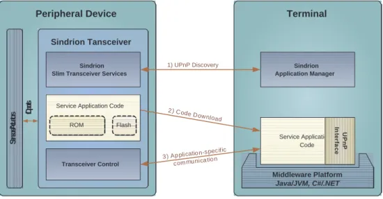
are assumed to have relatively loose cost and power restrictions. Fig.2.1 shows the basic communication procedures between a Sindrion Transceiver and a terminal. The three steps as shown in the figure are explained as follows.
Sensors / Actuators
Peripheral Device Sindrion Tansceiver
I/O ports
Terminal
1) UPnP Discovery
2 ) Code Download
3 ) Ap plicatio n-specific com mu nica tio n Service Application Code
Flash ROM
Sindrion Slim Transceiver Services
Transceiver Control
Middleware Platform Java/JVM, C#/.NET
Sindrion Application Manager
Service Application Code
UPnPInterface
Figure 2.1: Sindrion System
1. Discovery: The two end devices find each other in the standard UPnP discovery phase [7].
2. Code Download: The services provided by the Sindrion Transceiver is described by service application code, which is stored in the transceiver’s ROM. If the terminal does not yet contain this application code, it will be downloaded by the terminal.
3. Application-Specific Communication: The following communication between the downloaded service application on the terminal and its counterpart on the Sindrion Transceiver may be completely application-specific and does not have to be defined by any standard.
By this way, the Sindrion Transceiver is integrated into the UPnP network through the standard but relatively simple UPnP discovery protocol. Other complex UPnP protocols are sourced out to the terminal, which has high computational capability to act as a UPnP proxy for the Sindrion Transceiver. As a result, the Sindrion Transceiver can use low- performance components to minimize the cost.
Chapter 2. Wireless Sensor Networks 2.3. Sindrion Basic Concept
In the Sindrion system, the terminal normally has loose energy restriction, e.g. a desk- top is line-powered and a laptop or a PDA can be easily recharged. However, the Sindrion Transceiver is in many cases powered by cheap battery. Since changing or recharging the battery for a large number of Sindrion Transceivers is infeasible, power-saving is a very important design concern of the Sindrion Transceiver. Chp.3will discuss different possi- bilities to save power for a Sindrion Transceiver.
Chapter 3
Power Consumption Issue in WSNs
As aforementioned, power-saving is one of the most important design issues for the low- cost battery-powered wireless sensor devices. This chapter first gives an overview on pos- sible power-saving methods for wireless sensor networks. Second, the reason why schedul- ing the duty cycle of the MAC layer is the most efficient way for the Sindrion system to save power is presented. Then, some related low-power MAC protocols are introduced, and their advantages and disadvantages are discussed. Finally, the possibilities to further improve the available schemes are figured out, which defines the goal of this dissertation.
3.1 Introduction of Power Saving Methods
In [4, 8, 9], many power-saving possibilities that could be adopted throughout the whole design of WSN devices are discussed. They can be divided into three major categories:
low-power circuit design, fewer transmission, and more sleep.
3.1.1 Low-Power Circuit Design
Low power semiconductor and circuit design is a very important way to save power for a device, e.g. lowering the voltage of the digital circuits, optimizing the power amplifier in the RF analog circuit, minimizing the leakage of the devices, etc.
Chapter 3. Power Consumption Issue in WSNs 3.1. Introduction of Power Saving Methods
3.1.2 Fewer Transmission
The RF transceiver is one of the biggest power consumers in a wireless sensor device, so reducing the level of transmission power and the number of transmitted bits is supposed to be a very efficient way to save power.
Lower Transmission Power: The relation between the received power Pr and transmis- sion power Pt is Pr ∼ dPnt, where d is the distance and n is an exponent ranging from 2 to4. Therefore, adjusting the transmission power to a minimum level that just keeps the connectivity of the network can dramatically decrease the power consumption of the RF front end. Two typical examples of this way to save power are stated in [10,11].
Reduce Transmitted Bits: The bits sent to the air include two parts: payload and over- head. Both of them can be reduced.
The payload can be dramatically shortened by data compression or by fusing the infor- mation from neighboring devices before a long distance transmission [12,13]. However, it makes the system more complicated and requires more computation, which also consumes power. So a tradeoff is needed.
The overhead includes the header of data packets, the retransmitted data packets, and the signaling packets.
The header of the data packets could be shortened by using shorter addresses (e.g.
encoded MAC address [14]) and header compression (e.g. TCP/IP header compression [15]).
To reduce the number of the retransmitted data packets, one typical way is using Error Correction Coding (ECC), which can recover disturbed packets so that packet loss rate is reduced. However, ECC increases the length of the packet on the other side, so compromise is needed for certain channel condition.
The other way to minimize the retransmission overhead is using proper Automatic Re- peat reQuest (ARQ) protocols, e.g. data link layer ACK and transport layer TCP. However, ARQ also adds signalling packets causing additional overhead. So the tradeoff between the signaling and retransmission becomes the key issue. Some researches have been done on this topic, e.g. modified versions of TCP have been proposed to optimize the TCP perfor- mance in Mobile Ad hoc NETwork (MANET) and WSNs [16–19].
Chapter 3. Power Consumption Issue in WSNs 3.2. Power Saving Methods for Sindrion
3.1.3 More Sleep
Switching the whole or part of the system to the sleep mode as much as possible could save power with a factor of tens or even hundreds. Normally, either high-layer application scheduling (e.g. [20–23]) or low-layer MAC scheduling (e.g. [24–26]) could determine when and which part of the system should be switched off. The disadvantage of this idea is that a sleeping system is apt to be inertia for a happening event, consequently the com- munication delay is increased. Therefore, the tradeoff between sleep and delay, i.e. power and delay, for a certain application becomes the key issue. To this end, the questions faced by a system designer are how to divide the system into multiple hardware power domains and how to arrange the sleeping schedules for these domains according to the requirements of the application.
3.2 Power Saving Methods for Sindrion
Among the above three power-saving methods, low-power circuit design is out of the scope of the Sindrion project. Nevertheless, further discussion is needed to determine what the key is to save power for the Sindrion Transceiver:fewer transmission,more sleep, or both.
This decision should be based on both the software and hardware requirements of the Sindrion Transceiver.
The Sindrion system, as a kind of sensor/actuator network, is a low-rate low-traffic wireless network, because sensing and controlling occur quite rarely with intervals ranging from minutes up to months in most applications. For example, the temperature of a house might be measured each 10 minutes, but the water meter may be read out only once in several months.
In a low-traffic network, devices are mostly in idle state. As a result, most power is consumed by the idle state instead of data transmission. Therefore, usingfewer transmis- sionto minimize the power consumption of each data transmission is supposed to be not very effective, which will be proved later in Sec.5.2.4.
On the other hand, enabling more components to sleep more during the idle state could have a significant effect on power-saving in the low-traffic case, which needs the support from a dedicated multiple power domain hardware structure and power management algo- rithms. To roughly estimate the power consumption of this method, we should first take a
Chapter 3. Power Consumption Issue in WSNs 3.2. Power Saving Methods for Sindrion
look at the hardware components chosen for the prototype of the Sindrion Transceiver.
• RF transceiver: Data is transmitted and received by a commercial RF transceiver TDA5255E1 [27], which works in the 434MHz Industrial, Scientific, and Medical (ISM) band using Amplitude Shift Keying (ASK) or Frequency Shift Keying (FSK) modulation scheme. The data rate is less than100kbit/s.
• FPGA: For synchronization, modulation coding, and ECC, a Field Programmable Gate Array (FPGA) [28] is needed to process the data to and from the RF transceiver.
• Microcontroller:High-layer protocol processing is conducted in a single-chip high- performance 16-bit microcontroller with multiple on-chip A/D converters, timers, and memory modules [29]. It fits the requirements of the UPnP and TCP/UDP/IP protocol stack. Furthermore, it also supports idle and power down modes with flexi- ble power management.
• RTC: A Real Time Clock (RTC) is needed by the UPnP discovery protocol for refreshing purpose. A flash microcontroller [30] is used, which provides more im- plementation flexibility than a normal RTC.
• Memories:Memory includes external RAM [31] and flash [32].
• Others: There are some additional components used, e.g. the wake-up logic of the RF transceiver, the FPGA, and the microcontroller.
The power consumption of these components is listed in Tab.3.1.
Table 3.1: Power Consumption of the Components
Components Work Power Standby Power
RF transceiver Tx:39.9mW / Rx:27mW Sleep:27µW
FPGA Active:20mW Leakage:1.5µW
Microcontroller Active:33mW Sleep:90µW
RTC Working:230µW Idle:75µW
Memories Working:87mW Idle: 3.6µW
Others - Leakage:15µW
Note: system voltage –3V, microcontroller clock frequency –9MHz.
Chapter 3. Power Consumption Issue in WSNs
3.3. Available Low-Power MAC Layer Duty Cycle Scheduling Schemes
Among the above components, it is not difficult to switch the microcontroller and the FPGA to sleep or off mode when there is no traffic on the network. However, the RF transceiver should normally keep staying in receive mode because a packet could come at any time. So how to enable the RF transceiver to sleep during the idle state without severely affecting the data communication becomes the key question to be answered. This is normally solved by so-called MAC layer duty cycle scheduling, where the duty cycle denotes the percentage of the working time of a component. It is estimated in [4] that1%
duty cycle for the RF transceiver can reduce the overall system power consumption by a factor of at least 50.
As shown in Tab.3.1, the power consumption of the Sindrion Transceiver in a standby mode without duty cycle scheduling is
0.1851mW + 27mW = 27.1851mW. (3.1) The power consumption with a1%duty cycle of the RF transceiver is
0.1851mW + (27mW ×0.01 + 0.027mW ×0.99) = 0.48183mW. (3.2) So, power is saved by a factor of about56.
The above estimation shows that MAC layer duty cycle scheduling for the RF trans- ceiver could save a huge amount of system power for the Sindrion Transceiver. Therefore, the MAC layer duty cycle scheduling is the key power-saving method for the Sindrion Transceiver.
Until now, several low-power MAC layer duty cycle scheduling schemes have been proposed. Some typical examples will be briefly presented in the next section.
3.3 Available Low-Power MAC Layer Duty Cycle Schedul- ing Schemes
So far, quite some researches have been done on low-power MAC layer duty cycle schedul- ing, e.g. [24–26,33–36]. The IEEE802.15.4 MAC, the preamble sampling, and the WiseMAC are three mostly related work and will be briefly introduced in this section.
Chapter 3. Power Consumption Issue in WSNs
3.3. Available Low-Power MAC Layer Duty Cycle Scheduling Schemes
3.3.1 IEEE 802.15.4 LR-WPAN MAC Layer
The IEEE 802.15.4 Low-Rate Wireless Personal Area Network (WPAN) standard was first issued in October 2003 [33]. There is also an industrial alliance called Zigbee using this open global standard. The IEEE 802.15.4 standard specifies the Physical (PHY) layer and the MAC layer protocol to enable low-cost low-power short-range wireless devices to communicate. So, it could also be a choice for WSNs.
The IEEE 802.15.4 standard provides a MAC layer duty cycle scheduling scheme to save power in a master-slave star topology. A so-called superframe structure is used to define the basic arbitration scheme of the network, as shown in Fig.3.1. The master of the star, which has relatively unlimited power and computing capability compared to the slaves, periodically broadcasts a beacon indicating the structure of the superframe, i.e. the Beacon Interval (BI), the superframe duration, and the number of slots for the Contention Access Period (CAP) and the Contention Free Period (CFP). The minimum beacon length is 26 bytes. The length of the beacon interval cannot be arbitrarily chosen, but is determined by
BI = 16·60·2BO
SymbolRate, (3.3)
where the Beacon Order (BO) is an integer between 0 and 14 and SymbolRate is the symbol rate of the RF transceiver.
15 0 1 2 3 4 5 6 7 8 9 10 11 12 13 14
Contention Access Period (CAP) Contention Free Period (CFP)
Beacon Beacon
Superframe Duration (SD)
Beacon Interval (BI)
Inactive
GTS GTS
Figure 3.1: The IEEE 802.15.4 MAC Superframe Structure
The beacon also includes the information about to which slave(s) the master has packet(s) to transmit in the following period. A slave should periodically wake itself up to listen to the beacon. If the beacon indicates that there is a pending packet for the slave or if the slave has a packet for the master, the slave keeps awake for the communication in the CAP or CFP. If there is no packet, the slave goes back to sleep until the next beacon.
In the CAP, slaves use slotted Carrier Sense Multiple Access (CSMA) with exponential backoff to contend with each other for the channel. After getting the access right to the
Chapter 3. Power Consumption Issue in WSNs
3.3. Available Low-Power MAC Layer Duty Cycle Scheduling Schemes
channel, an uplink (slave to master) frame is directly sent to the master, then the master answers an acknowledgement (ACK). This is called a DATA-ACK session. To send a downlink (master to slave) frame, the slave should first send a data request command to the master so that the master knows the availability of the slave. The master then sends the downlink data frame to the slave and waits for an ACK from the slave. This is called a REQUEST-DATA-ACK session.
In the CFP, a Guaranteed Time Slot (GTS) can be assigned to a certain slave by the master in the beacon to support time critical streaming applications, e.g. continuous control signals from a mouse or a game panel. No CSMA is needed in GTSs.
To realize broadcast, the master puts the broadcast packet from the upper layer into the beacon as payload, so that all the slaves can receive it during listening to the beacon.
However, because of the limited space of the payload in the beacon, up to only 52-byte upper-layer broadcast packets are supported.
The IEEE 802.15.4 MAC layer duty cycle scheduling scheme enables a slave to be awake for only the beacon length in each period when there is no traffic. The ratio between the beacon length and the beacon interval is the duty cycle. Since the beacon length is nearly a constant, the only way to reduce the duty cycle is to increase the beacon interval, which increases the response time on the other side. So a proper beacon interval should be chosen according to the power and delay requirements of the application.
Note that the superframe can only be used in a star topology with one master, because beacons from multiple masters could confuse a slave that can hear all of them. For other topologies, the IEEE 802.15.4 standard provides no power-saving solution.
3.3.2 Preamble Sampling
Preamble Sampling is another MAC layer duty cycle scheduling scheme proposed in [34].
The basic idea of this scheme is shown in Fig.3.2.
The RF transceiver of a device periodically wakes itself up for a very short time, during which it detects whether the channel is occupied according to a Received Signal Strength Indicator (RSSI). If the channel is occupied, the RF transceiver wakes up other parts of the device to listen to the signal on the channel. Otherwise, it returns to sleep. This is the so-called sampling. To send a frame to such an RF transceiver that is sampling the channel, a transmitter has to first transmit a Wake-Up-Signal (WUS) with a length that is at least
Chapter 3. Power Consumption Issue in WSNs
3.3. Available Low-Power MAC Layer Duty Cycle Scheduling Schemes
Wake-Up-Preamble (WUP) Data
Transmitter
Receiver
Sampling Period Sampling time (Tsample)
Figure 3.2: The Preamble Sampling Basic Idea
equal to the sampling period, so that the sampling RF transceiver is ensured to hear the WUS and wakes up the device to receive the data frame following the WUS. The WUS in [34] is a simple sync preamble, called Wake-Up-Preamble (WUP).
The preamble sampling scheme is more efficient in the sense of power-saving compared to the IEEE 802.15.4 MAC because of the following two reasons. First, the sampling time (Tsample) is only the receiving time of several bits. It is much shorter than the time required for hearing a beacon, so the duty cycle of the preamble sampling scheme is less than that of the IEEE 802.15.4 MAC if the sampling period is chosen equal to the beacon interval.
Second, sampling the RSSI can be executed by the RF transceiver alone without the aid from other modules, while the IEEE 802.15.4 MAC needs a MAC module to parse the beacon. So the power consumption during the time for sampling the preamble is also less than that for listening to the beacon in the IEEE 802.15.4 MAC. Another advantage of the preamble sampling scheme is that it could be also deployed into a multiple-master topology or even a peer-to-peer topology.
One drawback of the preamble sampling scheme is its low efficiency of channel ca- pacity because of the transmission of the long WUS. The length of the WUS is equal to the sampling period, which is ideally adapted to the response time of the application – in the order of hundreds of milliseconds or even longer. However, the data frame length in WSNs is normally quite short and takes only tens of milliseconds to transmit. As a result, the WUS become the major traffic on the channel instead of normal frames, which dra- matically reduces the channel capacity for the normal frames. That is the reason why the preamble sampling scheme is only well-suited for networks with sporadic traffic where the channel capacity is not a critical factor.
Another disadvantage of the preamble sampling scheme is the high transmission energy consumed for sending the long WUS. So it is normally used in a master-slave topology,
Chapter 3. Power Consumption Issue in WSNs
3.3. Available Low-Power MAC Layer Duty Cycle Scheduling Schemes
in which the energy constraint of the master is loose so that first, the transmission energy of the long WUS is not a heavy burden any more; second, the master can keep in receive mode and the slave needs no WUS before sending a data packet to the master.
The other negative effect caused by the long WUS is overhearing. Since the WUS has the length of the sampling period, all devices in the transmission range are woken up. Those devices that hear the WUS but are not the destination of the packet are called overhearers. They also have to keep awake until they receive the destination address of the data frame. This overhearing effect drastically decreases the power efficiency achieved by the short-period low-power RSSI sampling.
3.3.3 WiseMAC
To reduce the disadvantages caused by the long WUS, the so-called WiseMAC (Wireless SensorMAC) based on the preamble sampling scheme has been proposed to shorten the length of the WUS [35–38].
The underlying idea is that if a device knows the sampling schedules of its neighbors, it can send a very short WUS to wake up the destination device without inducing many over- hearers. However, to know the schedule, synchronization among neighbors is necessary.
The WiseMAC achieves a loose synchronization by storing a neighbor’s sampling schedule that is piggybacked on the last received ACK from the neighbor. So a very short WUS can be used for the next frame according to the stored schedule. However, the insta- bility of the cheap quartz in small devices causes quite large clock drift, so that the length of the WUS must be prolonged again to compensate for the clock drift, especially if the schedule has been received a long time ago.
Assuming the frequency tolerance θ of the quartz is around 30 ppm, and the time elapsed since the last received schedule isL, the transmitter should start to send a(4θL+ Tsample)-long WUS2θLahead of the stored schedule to ensure to wake up the destination device, as shown in Fig.3.3. Therefore, the higher is the traffic, the smaller is the L, so the shorter is the WUS. As a result, overhearing and channel occupation are dramatically reduced, so that the WiseMAC also works well in relatively high-traffic networks.
The performance of the WiseMAC protocol in a master-slave star topology has been evaluated in [35]. It consumes around half of the power as the IEEE 802.15.4 MAC in most cases. In [36], the WiseMAC protocol has also been compared to two other famous sensor
Chapter 3. Power Consumption Issue in WSNs 3.4. Possibilities for Further Improvement
WUP Data
Transmitter
Receiver
Nominal Sampling Period
+ Tsample
Tsample
Figure 3.3: The WiseMAC Basic Idea
MAC protocols, S-MAC [25] and T-MAC [26], in a peer-to-peer topology with multihop routing. The WiseMAC shows again a better result in the sense of power consumption.
Nevertheless, there are still many long WUS in the WiseMAC because of the clock drift compensation. In this case, the inventors of the WiseMAC have suggested to repeat the data frame in the WUS instead of using the meaningless WUP, as shown in Fig.3.4.
The data repetition scheme, which will be called the Rep scheme later, can dramatically decrease the negative effect caused by overhearing, because each overhearer can receive a complete data frame after being woken up so that it knows it is an overhearer and goes back to sleep immediately. The average waiting time for an overhear is 1.5times of the data frame transmission time.
Transmitter Data
Destination
Nominal Sampling Period
Data Data Data Data Data
Overhearer
+ Tsample
Tsample
Figure 3.4: The Data Repetition Basic Idea
3.4 Possibilities for Further Improvement
As described above, the IEEE 802.15.4 MAC is an open global standard. It synchronizes all the devices by a combination of Time Division Multiple Access (TDMA) and random
Chapter 3. Power Consumption Issue in WSNs 3.4. Possibilities for Further Improvement
access. However, it only offers a power-saving mechanism for master-slave star topology, which highly limits its range of usage.
In the preamble sampling scheme, the RSSI sampling allows the receiver to work more power efficient for shorter time during the on-duty period compared to the beacon listening in the IEEE 802.15.4 MAC. It gives potential to achieve a much more power-efficient scheme. The other big advantage of the preamble sampling is that it could be used in any network topology.
However, the preamble sampling scheme is totally asynchronous, so that a very long WUS is needed, which not only is channel inefficient, but also generates too many over- hearers wasting a large amount of energy. To this end, the WiseMAC protocol has been proposed to shorten the length of the WUS by loosely synchronizing the neighboring de- vices, which improves the preamble sampling scheme.
Nonetheless, long WUSs are still needed in many cases. Firstly, the very beginning packets between the neighbors should be sent with a long WUS, which occurs frequently for a mobile device. Secondly, the clock drift compensation requires a longer WUS that could be up to the length of the sampling period for a low-traffic case. Thirdly, a broadcast packet must always use a long WUS to wake up all the neighbors. Besides application layer broadcast and multicast traffic, broadcast packets are also sent frequently in networks with mobile devices during network discovery, handshaking, multihop routing, etc.
To this end, the Rep scheme has been proposed to reduce the negative effect caused by the long WUS. Although data repetition can improve the WiseMAC, it is not the best choice in case of long WUS because of the following reasons:
• Repeating data is not efficient enough for long data frames, because each overhear has to wait1.5times of the data frame transmission time on the average.
• The destination of a unicast frame still has to wait until the end of the last repetition of the data frame to answer the ACK, wasting a lot of energy.
The Sindrion system has quite a number of long packets because of the UPnP and TCP/UDP/IP protocol stack. Theadvertisementandsearchmessages in UPnP are at least 100 bytes in length [7], and the application control packet is from 2 to 500 bytes in length (mostly around 20 bytes). Adding the TCP/UDP/IP header, the MAC header, and the PHY overhead such as ECC and modulation coding, the overall length of a data
Chapter 3. Power Consumption Issue in WSNs 3.4. Possibilities for Further Improvement
frame is longer than 100 bytes and even up to several hundreds bytes, which is very long for WSNs.
Therefore, for the Sindrion system, there is still space for further improving the pream- ble sampling scheme by optimizing the case of long data frames.
Chapter 4
Ultra Low Power MAC Layer Wake-Up-Frame Scheme
As discussed in Chp.3, MAC layer duty cycle scheduling combined with a dedicated hard- ware power domain structure is the key method to realize an ultra low-power Sindrion Transceiver. In this chapter, the so-called Wake-Up-Frame (WUF) scheme is proposed to further improve the preamble sampling scheme with the help of an elaborate multiple power domain hardware architecture. Furthermore, the combination of the WUF scheme and the WiseMAC is also discussed.
Note that to make the description clearer, the basic preamble sampling scheme using the WUP in [34] is called the WUP scheme in the rest of the dissertation, the termpreamble samplingdenotes only the general concept that a receiver periodically samples the channel, and thepreamble sampling schemeincludes all the schemes that use thepreamble sampling technology.
4.1 Multiple Power Domain Hardware Architecture
Fig.4.1shows the basic hardware structure of the Sindrion Transceiver prototype. It com- prises four major parts: an RF transceiver, an FPGA, a microcontroller, and an RTC. Note that external memory and sensor/actuator are not included in this figure for simplicity.
Chapter 4. Ultra Low Power MAC Layer Wake-Up-Frame Scheme 4.1. Multiple Power Domain Hardware Architecture
Antenna
Microcontroller
FPGA
RF Transceiver
R T C Serial I/O
Serial I/O
RSSI Wake-Up
Logic Wake-Up
Logic Power Ctrl.
Serial I/O MAC Serial I/O
Internal Timer
Modulation
Power Domain 1
Power Domain 2
Power Domain 3
Figure 4.1: The Sindrion Hardware Architecture
The device is divided into three power domains as follows.
1. RF Transceiver: When there is no traffic on the network, only the RF transceiver periodically wakes itself up to sample the channel.
The TDA 5255E1 [27] is chosen as the RF transceiver, because it provides a so-called self-polling mode, which facilitates the preamble sampling scheme by default. In the self-polling mode, the RF transceiver is periodically woken up by an internal timer.
Upon sampling, the RF transceiver detects the level of the RSSI and the data rate of the demodulated signal. If the RSSI exceeds a programmable threshold and the data rate matches a predetermined value, a pulse is generated on an output pin, which could be used to wake up other components of the device. This Data Rate Detection (DRD) function is completed within a very short time period, typcially the length of 3 Manchester-coded bits, i.e. 6 ASK/FSK modulated symbols.
Compared to the traditional preamble sampling based simply on the RSSI, this DRD function could significantly improve the system power efficiency by decreasing the unnecessary wake-up. If only the RSSI is used as the sampling criteria, strong noise or interference from other systems using the same frequency band could also wake
Chapter 4. Ultra Low Power MAC Layer Wake-Up-Frame Scheme 4.2. The Wake-Up-Frame Scheme Description
up the device. This is especially important for a wireless network operating in the ISM-band, where typically a number of systems share the same frequency band gen- erating a lot of interference. Moreover, different data rates can be used for the WUS and other normal frames, respectively, so that data frames and ACKs cannot wake up overhearers because of the DRD, which further reduces the probability of unnec- essary wake-up. To further prove the advantage of using DRD, quantitative analysis is conducted in Sec.5.2.4.
2. FPGA:When the RF transceiver detects a signal with enough strength and valid data rate, the FPGA [28] is woken up to receive the data frame. If the frame is addressed to this device, the FPGA wakes up the microcontroller.
3. Microcontroller: After being woken up by the FPGA, the microcontroller [29]
processes the received data frame accordingly.
Besides, an RTC [30] is always running for the need of UPnP discovery. This RTC will be also utilized by the WUF scheme, which will be introduced later.
By combining this delicate power domain structure, the MAC layer duty cycle schedul- ing, and other power management facilities of the microcontroller, different components can be woken up only on demand to save power.
4.2 The Wake-Up-Frame Scheme Description
4.2.1 The Wake-Up-Preamble Scheme
Before introducing the WUF scheme, it is necessary to first show how the WUP scheme works on the aforementioned hardware architecture (See Fig.4.2).
In the figure, a low level of the line means the component is in sleep state, a high level in working state (receiving, transmitting, idling, or calculating), and a slope in setup state.
The meanings of the shown parameters are: Tsample andTcycle are the times for sampling and cycle period (i.e. the sampling period in Sec.3.3.2), respectively; Ts rf, Ts f pga, and Ts µc denoted by slopes are the setup times for the RF transceiver, the FPGA, and the microcontroller;TdataandTack are the times needed to transmit a data frame and an ACK frame;Tto addr is the time to transmit a data frame until the destination MAC address; Tt
Chapter 4. Ultra Low Power MAC Layer Wake-Up-Frame Scheme 4.2. The Wake-Up-Frame Scheme Description
Wasted Energy Wasted Energy Wasted Energy
Wasted Energy
ACK ACK
WUP Data
Tsample
Destination:
RF Sampling Transmitter:
WUP
Destination:
FPGA Ts_fpga
Destination:
Microcontroller Ts_µc
Tcycle Tt
Tdata
Tack
Tµc Destination Address Tto_addr
Ts_rf
Overhearer:
RF Sampling
Overhearer:
FPGA
RF wakes up FPGA
FPGA wakes up RF
FPGA wakes up Microcontroller Twup
Figure 4.2: The Wake-Up-Preamble Scheme
is the transition time between transmit and receive modes of the RF transceiver;Tµc is the time needed for the microcontroller to process the data frame.
The operation of the transmitter, the destination, and the overhearer in the WUP scheme are as follows:
• Transmitter: For calculating the length of the WUP (Twup), the worst case should be taken into consideration. I.e. the beginning of the WUP just misses the sampling period of the destination, and the setup time of the RF transceiver and of the FPGA should also be included.
• Destination: When the destination RF transceiver detects the WUP, it wakes up the FPGA, and then the FPGA sets the RF transceiver into normal receive mode.
Afterwards, both the RF transceiver and the FPGA have to wait for the data frame.
After the data frame has been received by the FPGA, the microcontroller is woken up to answer the ACK and process the data. After sending the ACK, the RF transceiver and the FPGA go to sleep.
• Overhearer: The RF transceiver and the FPGA are woken up in the same way as in the destination case. However, when the FPGA receives the destination MAC address of the data frame, it knows that it is an overhearer, and then it switches off
Chapter 4. Ultra Low Power MAC Layer Wake-Up-Frame Scheme 4.2. The Wake-Up-Frame Scheme Description
the RF transceiver and itself. Note that it is not necessary to wait until the end of the data frame, but just until the destination MAC address.
The negative effect of the long WUP is obvious. Both the destination and the overhearer have nothing to do but wait during the shadowed areas as shown in Fig.4.2. The length of this unnecessary waiting time is approximatelyTcycle/2on the average, which is in the order of hundreds millisecond or even longer, wasting a large amount of energy.
4.2.2 The Wake-Up-Frame Scheme
To eliminate the unnecessary waiting time in the WUP scheme, we propose to send a wake-up-frame (WUF) instead of the meaningless WUP. The WUF comprises multiple Short Wake-Up-Frames (SWUFs) as shown in Fig.4.3. Each SWUF is a complete but very short MAC frame containing the destination MAC address, a special position field, and a CRC checksum. The position field is a successively decreasing integer indicating the position of the SWUF in the whole WUF, as shown by the numbern down to1in the figure.
Saved Energy Saved Energy Saved Energy
Saved Energy
ACK ACK Data
Tsample
Destination:
RF Sampling Transmitter:
WUF
Destination:
FPGA Ts_fpga
Destination:
Microcontroller Ts_µc
Tcycle Tt
Tdata
Tack
Tµc Ts_rf
SWUF n SWUF 5 SWUF 4 SWUF 3 SWUF 2 SWUF 1
RTC
Overhearer:
RF Sampling
Overhearer:
FPGA
Set RTC Tswuf
Twuf Padding
Field
Figure 4.3: The Wake-Up-Frame Scheme
The operation of the transmitter, the destination, and the overhearer in the WUF scheme are as follows:
• Transmitter:The length of the SWUF (Tswuf) is a constant because all frame fields are fixed. For calculating the length of the WUF (Twuf), the worst case should be
Chapter 4. Ultra Low Power MAC Layer Wake-Up-Frame Scheme 4.2. The Wake-Up-Frame Scheme Description
taken into consideration. I.e. the beginning of the WUF just misses the sampling period of the destination, and the setup time of the RF transceiver (Ts rf) and the FPGA (Ts f pga) should also be included. Furthermore, an additional SWUF should be added to ensure that the receiver can hear at least one complete SWUF after being woken up. Note that(Tcycle+Ts f pga+Ts rf)normally cannot be exactly divided by theTswuf, so an extra padding field is used at the beginning of the WUF, as shown in the Fig.4.3.
• Destination: When the destination RF transceiver detects the WUF at any place, it wakes up the FPGA, and then the FPGA sets the RF transceiver into normal receive mode. Afterwards, the FPGA can receive a complete SWUF, e.g. SWUF number 4 in the figure. So it knows that it is the destination according to the destination MAC address in the SWUF. Then it calculates the remaining time before the data frame comes based on the position field. The calculation is simple because the length and the data rate of the SWUF are constants and known by each device. If the calculated result shows that the remaining time is still long enough, the FPGA switches off the RF transceiver, sets a timer in the RTC, and goes to sleep. Just before the data frame comes, the RTC wakes up the FPGA, then the FPGA wakes up the RF transceiver, so that they can receive the data frame. When the data frame is correctly received, the microcontroller is woken up to answer the ACK and process the data.
• Overhearer: The RF transceiver and the FPGA are woken up in the same way as in the destination case. However, when the FPGA receives an SWUF, it knows that it is an overhearer so that it can switch off the RF transceiver and itself immediately.
Note that, unlike in the WUP scheme, the FPGA of both the destination and the over- hearer must receive a complete SWUF with correct Cyclic Redundancy Check (CRC) to ensure that the decoded the destination MAC address is correct. If the CRC check is wrong, the FPGA should wait for another SWUF.
By sending multiple SWUFs, the RF transceiver and the FPGA of both the destina- tion and the overhearer can go to sleep during the unnecessary waiting time in the WUP scheme, as shown by the shadowed areas in Fig.4.3. The on time of the RF transceiver and the FPGA are limited to around 1.5Tswuf on the average. Since the SWUF is very short containing only the basic MAC header, the destination MAC address, and a one-byte posi- tion field, it takes only several milliseconds for transmitting. Therefore, the WUF scheme
Chapter 4. Ultra Low Power MAC Layer Wake-Up-Frame Scheme 4.3. The Wake-Up-Frame Scheme Analysis
minimizes the unnecessary waiting time from hundreds of milliseconds down to several milliseconds for each data frame. This drastically reduces the power consumption of both the destination and the overhearer.
4.3 The Wake-Up-Frame Scheme Analysis
This section qualitatively analyzes the gain and cost of the WUF scheme compared to the IEEE802.15.4 MAC and the WUP scheme based on the specially designed hardware architecture.
• IEEE 802.15.4 MAC: As aforementioned in Sec.3.3.1, the IEEE 802.15.4 MAC is a global open standard supporting low-rate time critical streaming applications.
However, it provides power-saving mechanism only for a star topology with one master. Moreover, the duty cycle scheduling using the periodical beacon generates relatively high overhead, which not only consumes the power but also occupies the channel. This overhead should not be so significant for WPANs with high traffic.
However, it could be a heavy burden for low-traffic WSNs. Another point is that the programming effort and the code size for the IEEE 802.15.4 MAC are relatively high, because supporting a combination of TDMA and CSMA random access is not a so simple task, especially for a low-cost slave device.
• The WUP Scheme:The WUP scheme based on the preamble sampling technology uses short-period and low-power DRD sampling instead of listening to the beacon in the IEEE 802.15.4 MAC. It not only dramatically decreases the power consumption, but also enables the protocol to work in any topology. The drawback of the WUP scheme is that the very long WUP for each data frame generates a long unnecessary waiting time for the destination as well as the overhears. Furthermore, it occupies a lot of channel so that it is not well suited to work in a high-traffic network. However, when the traffic is low, the long WUP could occupy less channel than the periodical beacon in the IEEE 802.15.4 MAC. Concerning the programming complexity, the WUP scheme using CSMA with exponential backoff is definitely simpler than the IEEE 802.15.4 MAC.
• The WUF Scheme: The WUF scheme drastically decreases the average unneces- sary waiting time for both the destination and the overhearer from 0.5Tcycle down
Chapter 4. Ultra Low Power MAC Layer Wake-Up-Frame Scheme 4.4. Wake-Up-Frame and WiseMAC Combination
to 1.5Tswuf. However, the WUF has basically the same length as the WUP, so it still works only for low-traffic networks. The complexity overhead introduced by the WUF scheme is not significant. Firstly, the FPGA decodes the MAC address of the SWUF. However, address decoding is nevertheless needed for data frame, so the same block can be reused. Secondly, the FPGA calculates the remaining time before the data frame according to the received position field. This is just a single multi- plication of two integers: the position field and a constant denoting the transmitting time of an SWUF. Thirdly, the FPGA needs a hardware connection and a software routine for setting the RTC, which is also not a big issue. All in all, the additional effort introduced by the WUF scheme is minor compared to the significant amount of power it could save.
4.4 Wake-Up-Frame and WiseMAC Combination
The WUF scheme saves power by minimizing the unnecessary waiting time. But it cannot solve the low channel capacity problem caused by the long WUS. However, as mentioned in Sec.3.3.3, the WiseMAC shortens the length of the WUS to reduce the channel occupa- tion as well as the power consumption. Nevertheless, long WUS still exists widely because of the clock drift, the mobility of devices, and the broadcast and multicast traffic. The WiseMAC has also proposed to repeat the data frame instead of the meaningless WUP to further reduce the power consumption in case of a long WUS. However, the Rep scheme has an average unnecessary waiting time of around 1.5Tdata for overhearers. It is much longer than the 1.5Tswuf in the WUF scheme, especially for the quite long Sindrion data frame as mentioned in Sec.3.4.
The WUF scheme and the WiseMAC optimize the preamble sampling technology via different methods and they are complementary to each other. Therefore, a combination of them is supposed to generate a further optimized solution based on the preamble sampling technology. The way of combination is just transmitting multiple SWUFs instead of the meaningless WUP in the WiseMAC protocol when the WUS is long.
To estimate the performance of the proposed WUF scheme and the idea of combining the WUF scheme and the WiseMAC, analytical computations will be conducted in Chp.5 to compare them with the related work in a master-slave star topology.