February 24th 2017
Last name:
First name:
Student number:
I conrm with my signature that I will process the written examination alone and that I feel healthy and capable to participate this examination.
I am aware, that from the moment, when I receive the written examination, I am a participant of this examination and I will be graded.
Signature:
• Provide on all sheets (including the cover sheet) your last name, rst name and student number.
• Use the provided sheets. Own paper must not be used.
• Place your ID card and your student ID card on your table.
• You are allowed to use a self prepared, single sided DIN-A4 sheet in the exam.
Only handwritten originals are allowed, but no copies.
• You are allowed to use a non-programmable calculator.
• Answers, written with pencil or red pen are not accepted.
• The time limit ist 90 minutes.
• Turn o your mobile phones!
Result:
Question: 1 2 3 4 5 6 7 8 9 10 11 12 13 Σ Grade
Maximum points: 11 3 4 5 3 5 6 8 7 10 6 5 17 90
Achieved points:
a) Fill out all empty fields.
(Please fill in each empty cell only one correct answer!)
Maximum points: 3
a) The following information come from existing twisted pair network cables. What information is provided about the shielding of these cables?
• E138922 RU AWM 2835 24 AWG 60◦C CSA LL81295 FT2 ETL VERIFIED EIA/TIA-568A CAT.5 UTP EVERNEW G3C511
UTP = Unshielded Twisted Pair
• E188601 (UL) TYPE CM 75◦C LL84201 CSA TYPE CMG FT4 CAT.5E PATCH CABLE TO TIA/EIA 568A STP 26AWG STRANDED
STP = Shielded Twisted Pair
• E324441 RU AWM 2835 24AWG 60◦C 30V CHANGJIANG TIA/EIA 568B.2 UTP CAT.5e
UTP = Unshielded Twisted Pair
• SSTP ENHANCED CAT.5 350MHZ 26AWG X 4P PATCH TYPE CM (UL) C(UL) E200579 CMG CSA LL81924 3P VERIFIED
SSTP = Screened Shielded Twisted Pair
• EC-net 7.5 m 11184406 13/03 PremiumNet 4 PAIR 26AWG S-FTP HF IEC 332-1 ENHANCED CATEGORY 5 PATCH CORD EN0173+ISO/IEC SFTP = Screened Foiled Twisted Pair
• (UL) E228252 TYPE CM 75◦C 24AWG 4PR UTP C(UL) E228252 CMR 73◦C ETL VERIFIED TIA/EIA 568B.2 CAT.5e
UTP = Unshielded Twisted Pair
Calculate the first and last host addresses, the network address and the broadcast address of the subnet.
IP Address: 130.120.20.123 10000010.01111000.00010100.01111011 Subnet mask: 255.255.240.0 11111111.11111111.11110000.00000000
Part for host IDs: xxxx.xxxxxxxx
Network address? 130.120.16.0 10000010.01111000.00010000.00000000 First host address? 130.120.16.1 10000010.01111000.00010000.00000001 Last host address? 130.120.31.254 10000010.01111000.00011111.11111110 Broadcast address? 130.120.31.255 10000010.01111000.00011111.11111111
binary representation decimal representation
10000000 128
11000000 192
11100000 224
11110000 240
11111000 248
11111100 252
11111110 254
11111111 255
Maximum points: 2.5+2.5=5
a) Split the class B network 189.23.0.0 for implementing 20 subnets. Calculate the subnet mask and answer the questions.
Network ID: 10111101.00010111.00000000.00000000 189.23.0.0 Number of bits for subnet IDs? 20 => 32 (= 25) => 5 bits
Subnet mask: 11111111.11111111.11111000.00000000 255.255.248.0 Number of bits for host IDs? 11
Number of host IDs per subnet? 211−2 = 2046
b) Split the class B network 129.15.0.0 into subnets, which contain 10 hosts each.
Calculate the subnet mask and answer the questions.
Network ID: 10000001.00001111.00000000.00000000 129.15.0.0 Number of bits for host IDs? 10 => 16 (= 24)=> 4 bits
Number of bits for subnet IDs? 16−4 = 12 bit Number of possible subnets? 212= 4096
Subnet mask: 11111111.11111111.11111111.11110000 255.255.255.240
binary representation decimal representation
10000000 128
11000000 192
11100000 224
11110000 240
11111000 248
11111100 252
11111110 254
11111111 255
This signal curve is encoded with NRZI and 4B5B. Decode the data.
Label 4B 5B Function 0 0000 11110 0 hexadecimal 1 0001 01001 1 hexadecimal 2 0010 10100 2 hexadecimal 3 0011 10101 3 hexadecimal 4 0100 01010 4 hexadecimal 5 0101 01011 5 hexadecimal 6 0110 01110 6 hexadecimal 7 0111 01111 7 hexadecimal 8 1000 10010 8 hexadecimal 9 1001 10011 9 hexadecimal A 1010 10110 A hexadecimal B 1011 10111 B hexadecimal C 1100 11010 C hexadecimal D 1101 11011 D hexadecimal E 1110 11100 E hexadecimal F 1111 11101 F hexadecimal
Maximum points: 5
Encode the bit sequence with 5B6B and NRZ and draw the signal curve.
Bit sequence: 11010 11110 01001 00010 01110
5B 6B 6B 6B 5B 6B 6B 6B
neutral positive negative neutral positive negative
00000 001100 110011 10000 000101 111010
00001 101100 10001 100101
00010 100010 101110 10010 001001 110110
00011 001101 10011 010110
00100 001010 110101 10100 111000
00101 010101 10101 011000 100111
00110 001110 10110 011001
00111 001011 10111 100001 011110
01000 000111 11000 110001
01001 100011 11001 101010
01010 100110 11010 010100 101011
01011 000110 111001 11011 110100
01100 101000 010111 11100 011100
01101 011010 11101 010011
01110 100100 011011 11110 010010 101101
01111 101001 11111 110010
The figure shows the physical connections of a network. All Bridges boot up at the same time after a power failure. Highlight in the figure which ports and Bridges are not used when the Spanning Tree Protocol is used.
Maximum points: 4+4=8
a) Error detection via CRC: Calculate the frame to be transferred.
Generator polynomial: 100101 Payload: 11010011
The generator polynomial has 6 digits =⇒ five 0 bits are appended 1101001100000 = Frame with appended 0 bits
XOR 100101|||||||
---v||||||
100011||||||
XOR 100101||||||
---vvv|||
110100|||
XOR 100101|||
---v||
100010||
XOR 100101||
---vv
11100 = Remainder Transferred frame: 1101001111100
b) Error detection via CRC: Check, if the received frame was transmitted correctly.
Transferred frame: 1011010110100 Generator polynomial: 100101
1011010110100 = Received frame XOR 100101|||||||
---vv|||||
100001|||||
XOR 100101|||||
---vvv||
100101||
XOR 100101||
---vv
00 => Transmission was error-free
a) Error Correction via simplified Hamming Distance (Hamming ECC method). Calcu- late the message, that will be transmitted (payload inclusive parity bits).
Payload: 10011010
Position: 1 2 3 4 5 6 7 8 9 10 11 12 Data to be transmitted: ? ? 1 ? 0 0 1 ? 1 0 1 0
0011 Position 3 0111 Position 7 1001 Position 9 XOR 1011 Position 11 ---
0110 = parity bit values
Position: 1 2 3 4 5 6 7 8 9 10 11 12 Data to be transmitted: 0 1 1 1 0 0 1 0 1 0 1 0
b) Error Correction via simplified Hamming Distance (Hamming ECC method). Verify, if the received message was transmitted correctly.
Received message: 0001101100101101
Position: 1 2 3 4 5 6 7 8 9 10 11 12 13 14 15 16 Received data: 0 0 0 1 1 0 1 1 0 0 1 0 1 1 0 1
00101 Position 5 00111 Position 7 01011 Position 11 01101 Position 13 XOR 01110 Position 14 ---
01010 Parity bits calculated XOR 00111 Parity bits received ---
01101 => Bit 13 ist defective!
Maximum points: 10
a) Sketch in the diagram of the network topology all collision domains.
b) Sketch in the diagram of the network topology all broadcast domains.
The diagram shows an excerpt of the transmission phase of a TCP connection. Complete the table.
Message ACK SYN FIN Payload length Seq number Ack number
1 0 0 0 150 1800 2500
2 1 0 0 250 2500 1850
3 1 0 0 200 1850 2750
4 1 0 0 50 2750 2050
Maximum points: 1+1+1+1+1=5
a) Mark the IP address of the Default Gateway in the output of route -n.
# route -n
Kernel IP routing table
Destination Gateway Genmask Flags Metric Ref Use Iface
0.0.0.0 192.168.0.1 0.0.0.0 UG 1024 0 0 eth0
192.168.0.0 0.0.0.0 255.255.255.0 U 0 0 0 eth0 192.168.0.1
b) Mark the MAC address of the Default Gateway in the output of arp -n.
# arp -n
192.168.0.191 ether 00:11:32:1c:03:f3 C eth0
192.168.0.21 ether 1c:b0:94:c4:a2:74 C eth0
192.168.0.1 ether 08:96:d7:2a:c6:06 C eth0
08:96:d7:2a:c6:06
c) The ifconfig tool says the local IP address is 192.168.150.71, but the website checkip.dyndns.orgsays the current IP address is 194.94.82.237. What technology is probably used?
Network Address Translation (NAT)
d) What specifies the Maximum Transmission Unit (MTU)?
The Maximum Transmission Unit (MTU) specifies the maximum payload of a frame (and thus the maximum size of an IP packet too).
e) Given the following configuration, what will happen if you send UDP segments with length 2500 Bytes viaeth0 from this machine?
# ifconfig eth0
eth0 Link encap:Ethernet HWaddr B8:27:EB:CE:50:E2
inet addr:10.0.0.9 Bcast:10.0.0.255 Mask:255.255.255.0 UP BROADCAST RUNNING MULTICAST MTU:1500 Metric:1
RX packets:6853190 errors:0 dropped:370 overruns:0 frame:0 TX packets:3453175 errors:0 dropped:0 overruns:0 carrier:0 collisions:0 txqueuelen:1000
RX bytes:1516614221 (1.4 GiB) TX bytes:306452639 (292.2 MiB) IP Fragmentation is used.
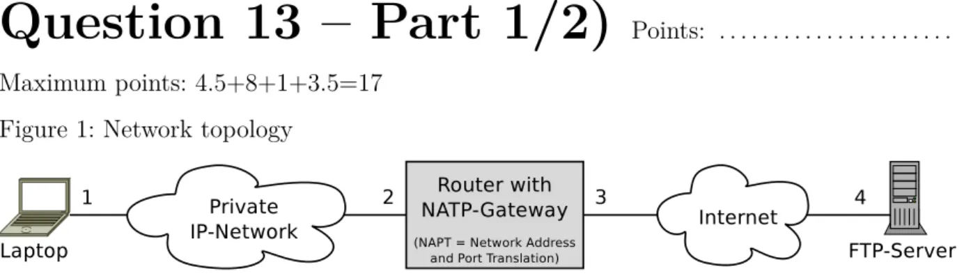
Figure 1: Network topology
Figure 2: Wireshark output of a received transmission on interface 1
Figure 3: Wireshark output of a received transmission on interface 3
The transmissions in figure 2 and figure 3 correspond with each other because they are used to transport the same FTP data. They transport the reply from the FTP server, which is initiated by a request of the laptop.
Maximum points: 4.5+8+1+3.5=17 a) Fill out all empty fields of the table.
Interface 1 2 3 4
MAC address 00:24:9b:0b:2a:ed 50:c5:8d:7a:d6:81 50:c5:8d:bb:2e:fa
IP address 192.168.50.17 194.94.80.16 217.160.233.106
Port number 4934 22345 21
b) Show the protocol stack (starting with OSI layer 2) of the transmission in Figure 3.
Fill in the correct number of Bytes of the headers, trailer and payloads. Also name the protocols used. Consider the FTP data as pure payload.
c) What is the amount of overhead in Bytes for the transmission of the FTP data (header and payload)?
(22 + 4 + 20 + 20) Byte = 66 Byte
d) Calculate the overhead ratio in % (possible OSI layer 1 overhead is ignored).
Size of the transmission = (75 + 22 + 4) Byte = 101 Byte Overhead (headers and trailer) = 66 Byte
Overhead ratio = 66 Byte
101 Byte = 0.6534∗100% = 65.35%