Universität Ulm| 89069 Ulm | Germany Faculty of Engineering and Computer Science Institute of Databases and Information Systems
Implementation and evaluation of a mobile Android application for auditory stimulation of chronic tinnitus patients
Master’s thesis at Ulm University
Submitted by:
Jan-Dominik Blome
jan-dominik.blome@uni-ulm.de
Reviewers:
Prof. Dr. Manfred Reichert Dr. Winfried Schlee
Supervisor:
Marc Schickler
2015
Version October 21, 2015
c
2015 Jan-Dominik Blome
Abstract
Tinnitus is a common symptom where the affected person perceives a sound without an external source. To support the development of new therapies a tinnitus tracking platform, including mobile applications, was developed at Ulm University in cooperation with the tinnitus research initiative. In the future, these mobile applications should be extended to include a simple game that requires the user to concentrate on an auditory stimulation, distracting them from their tinnitus. This is accomplished by using localization of an audio source as a game mechanic. The measurement of the offset between the position the user guessed for an audio source and its actual location could also serves as an additional data point. In this thesis an application for the Android operating system is designed that implements such a game and serves as a proof of concept. Since the Android API does not include the capability for positional audio, a separate audio API based on OpenAL was created as part of this thesis. This API as well as the framework developed to implement the game are designed to be reusable for future, similar projects. The game concept was also evaluated in a study using the demonstration application.
Contents
1 Introduction 1
1.1 Goal of this Thesis . . . 1
1.2 Tinnitus . . . 2
1.3 Structure of this Thesis . . . 3
2 Requirements Specification 5 2.1 Functional . . . 5
2.2 Non-Functional . . . 8
3 Audio Fundamentals 9 3.1 Digital Audio . . . 9
3.2 Binaural Audio . . . 13
3.3 Head-Related Transfer Functions . . . 16
4 Architecture 19 4.1 Project Structure . . . 19
4.2 Build System . . . 22
4.2.1 Gradle . . . 22
4.2.2 CMake . . . 24
4.3 External Dependencies . . . 25
4.3.1 Java Dependencies . . . 26
4.3.2 Native Dependencies . . . 27
4.4 Documentation . . . 28
5 Framework 29 5.1 Utility Libraries . . . 29
5.2 Audio API . . . 31
5.2.1 Basic Classes . . . 32
Contents
5.2.2 Positional Audio API . . . 33
5.2.3 Abstract Helper Classes . . . 36
5.2.4 Audio Filters . . . 39
5.2.5 Audio Utilities . . . 42
5.3 Sensor API . . . 44
5.3.1 Rotation Sensor API . . . 45
5.3.2 Sensor Data Filters . . . 47
5.3.3 Available Sensor Implementations . . . 49
6 OpenAL 53 6.1 The OpenAL Library . . . 53
6.2 Build Process . . . 54
6.3 Configuration . . . 55
6.4 Audio API Implementation . . . 58
7 Game Engine 61 7.1 Architecture . . . 61
7.1.1 Structure . . . 62
7.1.2 Components . . . 63
7.2 Engine . . . 64
7.2.1 Components API . . . 65
7.2.2 Game Data Classes . . . 70
7.2.3 Utility Classes . . . 73
7.3 Graphics . . . 75
7.3.1 Rendering Process . . . 77
7.3.2 Panorama Renderer . . . 82
7.3.3 Entity Renderer . . . 82
7.4 Audio . . . 84
7.5 Input . . . 87
8 Application 91 8.1 Common Application Classes . . . 91
8.2 Demo Application . . . 93
9 Evaluation 97 9.1 Participants and Methods . . . 97
9.2 Results . . . 98
Contents
9.3 Comparison . . . 101
10 Conclusion 105
10.1 Results . . . 105 10.2 Requirements Comparison . . . 106 10.3 Future Work . . . 108
List of Figures 109
List of Source Codes 111
List of Tables 113
List of Acronyms 115
Bibliography 117
1
Introduction
Tinnitus, that is the perception of a sound without an external source, is a common problem for a significant number of people [8]. In 2013 a mobile and web application to track individual tinnitus perception was developed at Ulm University in cooperation with the tinnitus research initiative (TRI) [44]. This application, called Track Your Tinnitus, allows people affected by a tinnitus to regularly record the severeness of their tinnitus perception. Collecting this data over the course of several weeks can reveal regular patterns that in turn might give clues to the cause of the increased severity. Besides allowing the user to track their own tinnitus, the application also enables researchers to access the anonymized data to further research the tinnitus symptom [44].
1.1 Goal of this Thesis
In this thesis, the foundation necessary to extend the Android version of the Track Your Tinnitus application with a game that requires the users to concentrate on a specific
1 Introduction
sound played through their headphones will be developed. Using binaural audio the source of the sound can be placed at a virtual location around the listener. The goal of the game is to locate this sound source. To further challenge the user the difficulty of this task may be increased by adding additional sound sources or ambient audio. The data gathered from a game session could then for example show if it is possible to distract the user from their tinnitus using this method. By measuring the offset between the actual position of the sound source and the position guessed by the user the game could also show if their ability for audio localization is affected. In this thesis the framework necessary to create such a game for the Android operating system will be developed and demonstrated in an application. This application will also be evaluated using a study. This framework can then serve as a basis to integrate the described or similar games into the Android version of the tinnitus tracking application, enabling it to be used for further data collection.
1.2 Tinnitus
Over the course of their lives many, if not most, people will experience a tinnitus [8]. The term tinnitus (from the Latin wordtinnire, to ring) describes the perception of a sound without an external sources. In some cases the sound has a physical source inside the body of the affected person, it is then called an objective tinnitus. But in case of the more prevalent type of tinnitus, the subjective tinnitus, there is no physical source of the noise [49]. This perceived sound can vary for each affected person, and it is typically describes as a pure tone, a hissing or a roaring noise [67]. It can be localized to the left or right ear, or it can appear to originate from the middle of the head [51].
Most of the time the tinnitus was triggered by an external source, like loud music or medication, and vanishes by itself over a time span of between a few seconds and up to a few days [8]. This type of tinnitus is called a transient tinnitus. If the tinnitus lasts more than six months it is called a chronic tinnitus. The chronic type of tinnitus is experienced by between 5 and 15 percent of the general population [67].
It is easy to imagine that such a condition can impact the quality of life of affected individuals. Effects can include sleep disturbances, difficulties to concentrate and psychiatric distress. About 1 to 3% of the general population report to be affected by a tinnitus strong enough to have these or other effects reduce their quality of life [67].
1.3 Structure of this Thesis
1.3 Structure of this Thesis
After the introduction, this thesis will detail the design, implementation and evaluation of the developed application. As first part of this process, the requirements for the project, both functional and non-functional, are specified in chapter 2. Since the auditory stimulation using positional audio is a core concept of the application, the basics of such a system are explained in chapter 3. Then, in chapter 4, the overall structure of the project is explained. Besides an overview of the included modules, this chapter also details the build process and the external dependencies of the application.
The project is split into different modules to improve reusability. The modules making up the basic framework of the application are described in chapter 5. This includes a positional audio application programming interface (API) developed for this project. To implement this API, the OpenAL library is used. How this library was integrated into the application is described in chapter 6. Since the application is designed like a game, a basic game engine was implemented as part of the project. It is described in chapter 7.
Finally, the actual application is detailed in chapter 8.
During development, a study was carried out to compare the implementation described in this thesis with similar applications developed for other systems. The results of this study are explained in chapter 9. Finally, in chapter 10, the final state of the project is described and compared to the requirements. The chapter concludes with an outlook over possible future improvements.
2
Requirements Specification
This chapter defines the requirements for the project. Both functional and non-functional requirements are specified. A comparison between these requirements and the imple- mented functionality of the application is done in section 10.2.
2.1 Functional
This section defines the functional requirements for both the application as well as the underlying framework. These requirements describe the expected behavior of the individual systems.
FR1 Android application for auditory stimulation
The main goal of this work is to create an application that lets the user react to auditory stimulations in the form of positional audio. The application should be designed as a game in order to motivate the user.
2 Requirements Specification
FR2 Positional audio sources
The application uses positional audio as a game mechanic. Since posi- tional audio support is not part of the Android API this feature has to be implemented as part of this project. The used audio framework should also support multiple simultaneous playing audio sources. This allows for the design of more challenging scenarios.
FR3 Ambient audio sources
In addition to the positional audio sources described in FR2, the audio framework should allow the use of at least one ambient audio track. Unlike the other audio sources this track is unaffected by the actions of the player.
This feature could also be used to make the game more challenging.
FR4 Per-source audio volume control
Both positional and ambient audio sources should have individual audio volume control. This allows fine-tuning the challenge presented to the player when creating a game scenario.
FR5 Audio file format
The application should support at least one commonly used compressed audio file format. This reduces the space required by the used audio files and shrinks the overall size of the application package ditributed to the users.
FR6 Audio framework
The capabilities implemented in FR2 to FR5 should be packaged as an audio framework that is usable independently of the actual application. This would allow it to be used in the future to implement different types of applications for Android based on positional audio.
FR7 Rotation detection using sensors
The application should be able to use the rotation sensors available on many Android devices to control the orientation of the player in the game. This could make the game more intuitively controllable by allowing the user to point the device into the direction they are facing and having the game react accordingly.
2.1 Functional
FR8 Alternative input using the touch screen
The application should support an alternative input scheme that does not depend on the rotation sensors of the device. This can be useful when either the device does not posses the required sensors or the current environment of thr user does not allow for free rotation. In that case the application should still be controllable by using the touchscreen of the device.
FR9 Graphics for the game
The application should be able to visualize the game world. This provides a way of showing the results directly to the user after they locked in their guess for the direction from which the target sound originated.
FR10 Picture representation of the target
When visualizing the game world, the application should be able to display a static picture representing the target at the correct location relative to the user. The picture should be changeable, so it can be chosen to match the sound that is played from that target.
FR11 Panorama picture as backdrop
The application should be able to draw a panorama picture as backdrop for the game world visualization. This panorama should be cropped to only show the parts visible from the current orientation of the player.
FR12 Reusable game engine
The systems described in FR7 to FR11 should be packaged as a game engine that can be used independently of the application. This facilitates the extension of the application with different game modes and allows these systems to be reused in another application.
FR13 Display results to the user
After the user has located a target, the difference between the guessed and the real position, as an angle in degrees, should be displayed to the user. In addition, the shown results should include the time it took the user before committing to a guess.
2 Requirements Specification
2.2 Non-Functional
This section defines the non-functional requirements, also for both the application and the underlying framework. These requirements describe characteristics of the individual systems not covered by the functional requirements.
NFR1 Backwards compatibility
The application and by extension the used libraries should work and be usable on all Android versions down to 2.3.3, or API level 10. This allows the application to be used on about 99.7% of all Android devices that access the Google Play Store [20].
NFR2 Small application package
Because mobile phones have limited storage capacity and application might have to be downloaded using mobile data connections the final package of the application should be kept small. It also should include all necessary assets to allow the application to work without requiring a network connection.
NFR3 Code documentation
All public classes and methods should have documentation in the form of JavaDoc comments. This increases their reusability by providing documen- tation directly inside the code.
NFR4 Extensibility and reusability
The application and its libraries should be designed with extensibility and reusability in mind. The goal of this requirement is to simplify future changes to the game and to allow the underlying systems to be reused to create a different application. This requirement is a more general version of the functional requirements FR6 and FR12.
NFR5 Good audio localization
The goal of the game designed in this thesis is for the user to localize an audio source by its sound only. For this to be possible the quality of the positional audio framework created as part of this application (see FR6) should be maximized.
3
Audio Fundamentals
The design of the application includes the blind localization of a virtual audio source as a key concept. To allow the user to determine the position of a target only by its sound, a positional audio system has to be used. In this section some concepts of digital audio as well as techniques that may be used to generate positional audio will be described.
3.1 Digital Audio
Sound, as perceived by humans, is a pressure wave in a medium, usually air. The frequencies contained in the wave determine the tonal content. Using a microphone such a sound wave can be converted to an electrical signal. This signal is still analog, to transform it into a digital format it needs to be sampled. The sampling happens by taking measurements of the signal amplitude at regular time intervals. This sampling rate has to be at least double the maximum frequency that should be recorded [4]. Since
3 Audio Fundamentals
[00101010]
Quantize Sample
(a) Encoder
Quantize-1 Interpolate
[00101010]
(b) Decoder
Figure 3.1: A PCM encoder and decoder [4]
humans typically can hear tones up to20 kHz, a typical sampling rate is44.1 kHz, used for example on audio CDs. The amplitude of each sample then has to be quantized to a binary value. Common binary representations are 16 bit signed integers, for example used on audio CDs, or 32 bit floating point numbers. This type of encoding is called pulse code modulation (PCM) [4]. Both a PCM encoder and a decoder are shown in Figure 3.1. If the audio signal contains multiple channels they are usually stored interleaved. This makes streaming of the data easier since all output channels can be fed from the same signal. By reversing the encoding process using a PCM decoder the data can again be transformed into an analog electrical signal that can be played back using a speaker.
It is also possible to transform a digital audio signal. This is done by a filter using digital signal processing (DSP). Since the audio data consists of discrete samples, such a filter is applied for each sample individually. A generic signal filter is shown in Figure 3.2, wherexn is the input sample andyn is the transformed output sample [2]. While the shown filter has exactly one input and one output signal this is not a requirement for a DSP system. A system could, for example, have several input signals and combine them to one output signal or create several output signals for a single input signal. They can also be combined by connecting the output of one system to the input of another.
Each DSP system is constructed from some common operations that are performed on a signal. In the following the operations used by filters and systems described in this thesis will be introduced. The first is the multiplication operator, shown in Figure 3.3. It
xn yn
Figure 3.2: A generic digital signal filter
3.1 Digital Audio
multiplies all incoming samples with a value. This scales the input signal by the supplied factor, calledgin the figure. For audio signals this is the equivalent of a volume control knob [2].
xn g yn
Figure 3.3: Multiplication of a signal with
gThe summation operator, shown in Figure 3.4, combines two signals by adding their respective samples. For this to work the signals must use the same sampling rate.
A gain factor is often applied to one or both input signals to prevent clipping of the produced signals [2].
xn1 + yn xn2
Figure 3.4: Summation of two signals
The final building block is the delay operator, shown in Figure 3.5. This operator buffers any incoming samples, up to a set delay value (kin the figure). Once the next sample is received, the oldest sample in the buffer is removed, becoming the new output value.
Then the newly received sample is added instead. The buffer works on the first in, first out (FIFO) principle. If no samples are available yet, the output of this operator is the value0[2].
xn Z-k yn
Figure 3.5: Delay of a signal by
ksamples
A common pattern used in DSP filters is called convolution. It can be thought of as an operation working on two arrays, resulting in a new output array. This can be written asy(n) =x(n)∗h(n)wherex(n)is the input array,h(n)is the filter array andy(n)is the output array. Each element of the output array is calculated by summing the last
yn=
N−1
X
i=0
xn−i·hi
(3.1)
3 Audio Fundamentals
3 2
1 4 1
3 2 1
7 17 15 11
+ +
h(n) x(n)
y(n)
Figure 3.6: Calculation of
ynas the result of the convolution of
x(n)and
h(n)Nelements of the input arrayx(n), each weighted by a corresponding factor stored in h(n), whereN is the length of theh(n)array. This calculation for a single element of the output array is also shown in Equation 3.1 and visualized in Figure 3.6. The resulting output arrayy(n)has the length ofx(n)plus the length ofh(n)minus1. [2]
The convolution operation can be realized as a DSP system, as shown in Figure 3.7.
This system is called a finite impulse response (FIR) filter. It is finite because the length of the outputy(n)can be determined from the length ofx(n)andh(n)[2]. The filter uses delay operations to keep the previous values in a buffer. They are then available to calculate the next output value. Each new output shifts all values down to the next delay operation. The output of these delay operations is multiplied with the associated value ofh(n)and finally added with all the other values to generate the result.
h1 Z-1
h2
+
Z-1
+
hN
xn yn
Figure 3.7: A finite impulse response filter
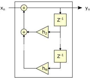
It is also possible to use a past output value of a DSP system as input by storing it using a delay operation. This is called a feedback loop. Using multiple delay operations allows using output values from further into the past. Unlike with the FIR filter, the length of
3.2 Binaural Audio
xn yn
Z-1 +
Z-1 h2
hN +
Figure 3.8: An infinite impulse response filter
the output of such a filter can not be determined from the length of the input. For that reason this type of filter is called infinite impulse response (IIR) filter. An example for such a filter is shown in Figure 3.8.
3.2 Binaural Audio
Humans possess the ability of sound localization, that is determining the position of an object based solely on the sound it is emitting. This is possible because the brain can analyze the differences between the audio heard by both ears. In this thesis, the term 3D audio refers to a system that can use this mechanism to create the illusion of a virtual, sound-emitting object for a user. The terms positional or binaural audio are also used synonymously. Such a system has to be able to direct different audio signals to each ear of the listener, otherwise no spatial localization is possible. This can easily be accomplished by using stereo headphones.
If both the consumed content as well as the position of the user are static, a binaural recording can be performed. This is done using a head, either a mannequin or the real head of the recording technician, that is equipped with a microphone in each ear [52].
The result of such a recording is limited in that the recorded content is static and the listener can only experience the acoustics of the position the recording was done from.
For interactive applications this is often not an option. They need a system that can generate the appropriate audio signals for both ears based on a virtual world.
3 Audio Fundamentals
distance
azimuth elevation
sound source listener
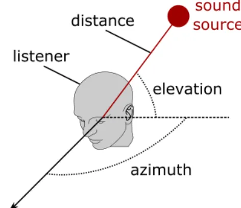
Figure 3.9: The coordinate system used for positional audio
To describe the position of a virtual audio source in the world a coordinate system has to be defined. In this thesis I will use a spherical coordinate system centered on the listener (see Figure 3.9). The position of each virtual sound source is then defined by three value: distance, azimuth and elevation.
Both the azimuth and the elevation angle describe the angular perception of the sound source. The azimuth is the angle from the front of the listener to the sound source around an axis perpendicular to the ground. When expressed in degrees,0◦is directly in front of the listener. The object can also be rotated up to180◦ to either side, with 180◦meaning the source is directly behind the listener. Since the ears are positioned at almost opposite sides of the head, human hearing is very perceptive to the azimuth of a sound source [2]. The elevation is limited to90◦, where90◦upwards is directly above the listener and90◦downwards is directly below the listener. While the placement of the two ears on a horizontal plane helps with the localization of sound sources around the listener, up- or downward positions are more difficult to discern [2].
There are two important cues used by the human brain to localize a sound source. The first is the interaural intensity difference (IID). A sound source to one side of the listener will be heard louder on the ear directed towards the source than on the other one. The difference in intensity is dependent on the frequency of the sound, it gets smaller with lower frequencies. The reason for this is that sound waves with a longer wavelength will diffract more around obstructions, like the head of the listener. Below approximately 1 kHz IID is no longer an effective localization cue [2]. Using volume differences to provide 3D audio cues is a very common technique used by computer games. Even
3.2 Binaural Audio
90°
0°
-90°
180°
Target
Target Percept
Percept
front-to-back
back-to-front
(a) Aimuth confusion
90°
0°
-90°
180°
Target
Target Percept
Percept
down to up
up to down
(b) Elevation confusion
Figure 3.10: Localization errors caused by ambiguity [52]
some of the very first 3D games, like Wolfenstein 3D by id Software, already used stereo-panning to simulate positional audio [72].
The second important cue is the interaural time difference (ITD). Any sound source located to either side of the listener’s head will have a different distance to each ear.
This means the ear located on the far side of the head as seen by the audio source is farther away and will receive the audio signal later than the other ear. This time difference between the two signals can be interpreted by the brain to help localize the source. It is most effective bellow a frequency of about1.6 kHz, after that the wavelength of the sound waves is smaller than the width of a typical human head [2].
Even when using both IID and ITD to localize a sound source there are still some possible ambiguities. They can result in a localization error, with a common error being a front and back reversal (see Figure 3.10a). These types of error typically result in a source in the frontal hemisphere being judged by the listener to be in the rear hemisphere, although the opposite is also possible [52]. The same type of error can happen with the elevation of an audio source, where up and down can be misjudged by the listener (see Figure 3.10b). These types of errors have their origin in the so called cone of confusion. Assuming a spherical head with symmetrically located ears canals, there are several possible source locations for any IID or ITD cue. An example of this is shown in Figure 3.11. The four marked points all produce identical IID and ITD cues, possibly leading to reversals on both the front-back and on the up-down axis. Besides these marked points every point on the circle also produces the same cues. They,
3 Audio Fundamentals
A
X B
Y
Figure 3.11: The cone of confusion [2]
together with the listener’s head, form the cone of confusion. In reality, the pinnae, or outer ears, provide additional cues that are not present when using a simplified model without the outer ears. These cues can also be interpreted by the human brain, possibly resolving an otherwise existing ambiguity [2].
There are more effects that might be desirable when creating a virtual acoustic envi- ronment. One of them is reverberation, caused by the reflection of the sound waves from obstacles in the environment [2]. Another is the doppler shift which is a change in perceived pitch in the sound emitted by moving objects [2]. Since neither of these effects will be used by the application discussed in this thesis they will not be explained in detail.
3.3 Head-Related Transfer Functions
To improve the ability of a listener to localize an audio source the effect of the pinnae on the audio signal can be simulated. The necessary transformation is done by applying two convolution operations to the audio signal, one for each ear (see Figure 3.13). The function applied for each ear is called a head-related transfer function (HRTF). The actual factors used by the HRTF (namedgnin the figure) depend on the relative position of the listener to the audio source. These factors can be derived from a measured impulse response. Such a measurement can be done using a dummy head that includes modeled pinnae. This approach was for example used by the Massachusetts institute of technology (MIT) Media Lab using a Knowles Electronics mannequin for acoustics research (KEMAR) dummy head (see Figure 3.12) [10]. Another way to obtain HRTF
3.3 Head-Related Transfer Functions
Figure 3.12: A KEMAR dummy head with pinnae [61]
measurements is by using a real human being equipped with microphones in their ear canals. This approach was for example used to create the Listen HRTF database, which contains the measured head related impulse responses of 51 test subjects [46].
Since the geometry of the outer ear varies from person to person, so does the corre- sponding HRTF. Ideally each user of a binaural audio system could have their own HRTF matched for their individual pinnae. But since the measurements necessary to generate an individual HRTF are complicated and require special equipment, this is not easily realized. Wenzel et al. have shown that using non-individualized HRTFs can still allow for a satisfactory ability to localize individual audio sources [71]. When using a non-individual HRTF, it should be based on data measured using a good localizer, meaning a person that can determine the position of real audio sources with a high accuracy [71].
When using the DSP system shown in Figure 3.13, the head-related impulse responses (HRIRs) applied with the FIR filters must use the same sampling rate as the audio data it is applied to. Otherwise either the audio data or the HRIR has to be resampled.
Since the HRTF data is based on measurements, it is only available for the points (defined by azimuth and elevation) where a measurement was taken. If the relative position of an audio source to the listener’s head does not exactly match one of these points, the HRTF data has to be interpolated by using the available measurement points surrounding the actual source position.
Since the user can change the orientation of the virtual listener, the latency of the audio system is also important. Experiments with head-tracking audio systems suggest that a latency of 60 milliseconds or below is undetectable to almost all listeners when no
3 Audio Fundamentals
h1 Z-1
h2
+
Z-1
+
hN
yR,n
h1 +
Z-1
h2 +
Z-1
hN
yL,n xn
hR hL
Figure 3.13: Convolution using a separate FIR filter for each ear [2]
low-latency reference tone is present [7]. Since this application requires the user to wear headphones that would block out such an external reference tone this lower bound is applicable to the game described in this thesis.
4
Architecture
In this chapter the overall architecture of the project is described. This includes an explanation of the different modules as well as the build system used to compile the project. The external depencendies used by the application are also described.
4.1 Project Structure
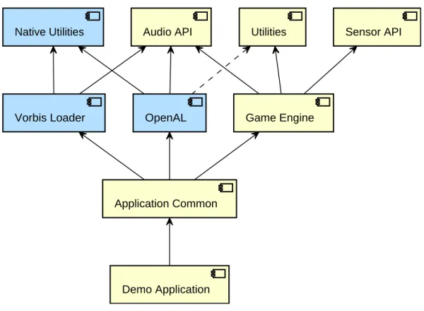
The project is split into several modules, as shown in Figure 4.1. Modules shown in blue include native code. Also shown are the dependencies of the modules to each other. A dashed arrow shows a dependency for the tests only.
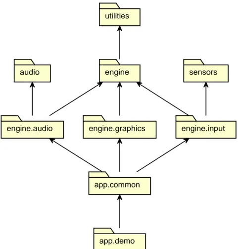
The Java code is also organized into different namespaces. A module usually contains all classes of one namespace. Exceptions are the audio modules, which all add to the same namespace and the engine module which uses sub-namespaces to further subdi- vide the code. The different namespaces used in this project and their dependencies are shown in Figure 4.2
4 Architecture
Native Utilities
Vorbis Loader OpenAL
Utilities
Game Engine
Audio API Sensor API
Application Common
Demo Application
Figure 4.1: Project module dependencies
Theutilitiesmodule contains static utility classes and functions. Currently it only con- tains functions to convert and normalize angles in degrees or radians. It is implemented in theutilitiesnamespace and described in detail in section 5.1.
Thenative utilitiesmodule is completely implemented in C++ without any Java code.
It contains classes and functions that facilitate the implementation of code using the Java native interface (JNI). Like the Java utility module it is described in section 5.1.
Thesensor APImodule defines a simple interface to access a rotation sensor on an Android device. It also includes adapters for some of the potentially available Android sensors to this interface. Both the interface and its implementations are defined in the sensorsnamespace. The module is described in detail in section 5.3.
Theaudio APImodule defines an implementation-independent API to access a posi- tional audio system. It also contains an audio data class, a WAVE file reader, audio filter implementations and support classes to help with an implementation of the API.
Everything in the module is contained in theaudionamespace. A detailed description can be found in section 5.2.
4.1 Project Structure
utilities
audio engine sensors
engine.audio engine.graphics engine.input
app.common
app.demo
Figure 4.2: Java package dependencies
TheVorbis loadermodule extends the audio API by adding an Ogg-Vorbis file reader to the audio namespace. Since the file reader is based on a native library, the module uses JNI and the native utilities module. The file reader class is described in subsection 5.2.5 together with the other audio API utilities.
TheOpenALmodule provides an implementation of the audio API. Since OpenAL is used as a native library this module also uses JNI and the native utilities module. In addition, the included tests depend on the Java utilities module. The implementation is also located in theaudionamespace. An explanaiton of the functionality provided by this module as well as more details about the OpenAL library can be found in chapter 6.
Thegame enginemodule defines the framework used in the application. It is imple- mented in theenginenamespace, which contains three sub-namespaces: The audio
4 Architecture
part of the game engine is implemented in theengine.audionamespace and de- pends on the audio API. The graphics part uses theengine.graphicsnamespace.
Finally, the input part is contained in theengine.inputnamespace. It makes use of the sensor API. More information about all parts of the game engine can be found in chapter 7.
The demo applicationmodule contains the actual Android application that is used to demonstrate the game concept. It is implemented in theapp.demonamespace.
Classes that might be of interest to other applications based on the game engine or the other framework modules are split into thecommonmodule, using theapp.common namespace. The application is described in chapter 8.
4.2 Build System
The project uses two different build systems. For the Java part of the project, Google’s Android build system, which is implemented as a plugin for Gradle, is used. For the native code CMake is used. Both build systems will be described in this section.
4.2.1 Gradle
The Java part of the project is build using Gradle. Gradle is a build automation tool that uses the Java-based Groovy programming language to configure the build process [40].
It is extensible using plugins. The Android build tools used for this project are one example of such a plugin. They are included in the Android software development kit (SDK) [15]. The Android Studio integrated development environment (IDE) can directly import and build a Gradle project using this plugin. When not using Android Studio, the build process can be started using the Gradle wrapper included with the source code. This is a batch or shell script, that can automatically download Gradle and run the build process [41]. This way no local Gradle installation is necessary.
The project is divided into the root project and several sub-projects. The configuration for the root project is done in thebuild.gradle file located in the root directory of the source tree. Here the used version of the Android build tools as well as the repository from which it is downloaded are specified. The repository used by the sub- projects to download any required Maven packages is also defined. In addition, the
4.2 Build System
ExtraPropertiesExtensionplugin is used to define variables that are available to all sub-projects (see Listing 4.1). Here the target Java, Android SDK and build tools versions are set. In addition, a list of all supported application binary interfaces (ABIs) and their priorities are defined. Also in the root directory is thesettings.gradlefile.
In this file all sub-projects are added to the main Gradle project.
1 minSdkVersion = 10
2 targetSdkVersion = 23
3 compileSdkVersion = 23
4 buildToolsVersion = ’23.0.1’
5 sourceCompatibility = JavaVersion.VERSION_1_7
6 targetCompatibility = JavaVersion.VERSION_1_7
7 supportedAbis = [’armeabi-v7a’, ’arm64-v8a’, ’x86’, ’x86_64’]
8 abiVersionCodes = \
9 [’armeabi-v7a’: 1, ’arm64-v8a’: 2, ’x86’: 3, ’x86_64’: 4]
Listing 4.1: Gradle project properties
Each sub-project also has its ownbuild.gradlefile, located in the root directory of the module. In this file the necessary plugins for the sub-project are applied. The ideaplugin is used to name the module for display purposes in Android Studio. The sub-projects also define their dependencies in this file. Both external as well as local dependencies are supported. Not shown in Figure 4.1 are the libraries sub-projects.
These Gradle projects contain no Java code and are only used to build and manage the external native libraries. This is done using a custom plugin, which will be described in the next chapter. Any Java dependencies are managed and if necessary downloaded by the Gradle build system.
Each sub-project either uses the Android application or the Android library plugin. For either of these plugins, the build options are set by using the global extra properties set in the root project. For the application project some additional configuration is required:
For versioning purposes both a version number as well as a name are set. The version number is used to handle automatic upgrades, the version name is only used when displaying the version to the user [39].
To reduce the overall file size of the final Android application package (APK), ABI splitting can be enabled. If this option is set, instead of packing all versions of the native libraries into the same APK file, a different file is generated for each supported CPU architecture.
Only the compiled libraries for this ABI are then packed into the associated APK file.
Since this project is based on several native libraries, using this option reduces the final
4 Architecture
size of the application file. Using the ABI splitting option requires some additional work when versioning. If a device supports more than one ABI it is important that the APK using the preferred ABI has a higher version number. Otherwise it could for example happen that an ARMv8 based device would use its backwards compatibility to run an ARMv7 version of the application instead of using the optimized ARMv8 version. To prevent this the million digit of the version number is set to a different code for each supported API. More modern or advanced ABIs get higher numbers so devices that support them use the optimal version for their hardware. For example, 64-bit ABIs get higher numbers then their 32-bit counterparts. The ABI also gets appended to the version name in a readable format.
The Android build system includes ProGuard, a program that shrinks, optimizes and obfuscates Java code [50]. For this project, ProGuard is used to further reduce the size of the final APK file. This is done by removing unused code from the external Java libraries used by this project. ProGuard is only enabled for release builds. Configuration is done in theproguard.profile located in the root of the application sub-project.
Besides the necessary configuration for external libraries this file also disables the obfuscation feature. This is done to help with debugging of the release version since any stack trace generated by the obfuscated version would itself also be obfuscated [33].
If enabled, the obfuscation of the stack trace can be reversed using theretracescript included in the Android SDK.
4.2.2 CMake
To compile native C or C++ code for Android applications, the Android native devel- opment kit (NDK) is used [13]. It includes the necessary compilers and libraries to build native code for the different Android platforms. Different versions of both the GNU compiler collection (GCC) as well as the Clang compiler are included. Native Android libraries can interact with Java code by using JNI. The Android NDK includes a version of GNU Make that can be used to build native libraries and applications.
While Android Studio allows the compilation of NDK projects, this capability is depre- cated. In May 2015 Google announced that a new system for building NDK projects will be released with version 1.3 of Android Studio [42]. This new version will include syntax highlighting for C and C++ code as well as debugging support for native code.
During the development of the application described in this thesis this new build system
4.3 External Dependencies
was not yet available. While a preview build of Android Studio 1.3 was released in July 2015 [14], including support for the new NDK features, the necessary Gradle plugin was still experimental. Since the API and by extension the domain-specific language (DSL) of this experimental plugin are likely to change [22], this new system to build native libraries is not yet used in this project.
Instead the cross-platform build system CMake is used [48]. This software allows the us- age of platform and compiler independent configuration files to control the build process.
These configuration files are processed by the CMake application and translated into makefiles for a chosen target compiler and platform. Cross-compilation is supported and the same configuration file can be used to generate makefiles for different target architectures. To build native libraries for the Android platform and its many ABIs, the android-cmakebuild scripts are used. These scripts were originally developed to compile OpenCV for Android by allowing the creation of makefiles that use the Android NDK. Using CMake as native build system also allows for an easy integration of other project that include CMake configration files. Once such project is the OpenAL library that is used by this project.
To facilitate the parallel development of the Java and the native code portions of this project, the CMake build process is integrated into the Gradle build. This is done by defining a plugin that adds new build tasks to the Gradle build process. The first task runs when a build of the Android application is started and generates a CMake configuration file. The contents of this file are defined in the Gradle project configuration file. It also includes directives to build all submodules that apply the CMake plugin. This CMake configuration is then used by another task to generate a makefile that builds all the native libraries required by the application. This task is defined and run several times, once for each supported ABI. Finally, tasks are added that run these makefiles and compile the actual libraries. These tasks are also defined for each ABI separately.
All tasks defined by the CMake build plugin are added as dependencies to the regular build process. This makes sure that all native libraries are up-to-date when the Android application is build using Gradle.
4.3 External Dependencies
In this section the external or third-party libraries used by the application described in this theses are introduced. They are split between Java and native dependencies.
4 Architecture
4.3.1 Java Dependencies
The project uses several third-party Java libraries. One of them is an implementation of the Java annotations introduced in Java specification request (JSR) 305 [57]. While these annotations don’t have any effect by themselves, a compatible IDE can use the additional information provided by using the annotations to find bugs that are not detected by the Java compiler itself. Since it is based on IntelliJ IDEA, the Android Studio IDE [16] can for example use the@Nonnulland the@Nullableannotations to detect incorrect handling of object references that might benull. While the Android support annotations also include nullness annotations [27], I decided to use the JSR 305 annotations because they provide a way of setting a default for method parameters.
This allows the annotations to be omitted in a lot of cases without loosing their benefits, reducing the clutter in the method signatures. Such a default value can be specified per Java package. The JSR 305 annotations are used in every Java module of this project.
The game engine module also depends on the Guava Java library developed by Google [25]. This library is mainly used for the collections it adds, including immutable implementations of many basic Java collection classes. The cache implementation as well as the precondition checking utilities defined by Guava are also utilized by the game engine. It also uses the JSR 305 annotations, extending the nullness checking done by the IDE to calls into the library. Since dependencies are transitive, any module depending on the game engine also has access to the full Guava library. To reduce the file size of the final APK, ProGuard is used to remove unused features of the library during the build process.
To facilitate the implementation of backwards compatible Android applications, Google provides several support libraries [38]. The application modules depend on both the v4
“support” as well as the v7 “appcompat” library. The support library can be used with Android API level 4 and above. It includes a backwards-compatible implementation of fragments. These are encapsulations of layouts that can be reused in different activities and were added in API level 11. Since the application targets API level 10, usage of the support library is required to make use of fragments. The appcompat library depends itself on the support library. It can be used with Android API level 7 and above. It provides activity classes that use the action bar user interface [11]. These activities are compatible with fragments designed using the support library. The appcompat library was also updated to enable the creation of user interfaces using the material design
4.3 External Dependencies
theme introduced with Android 5.0 [29]. This allows designing an application using the modern material theme while still maintaining backwards-compatibility.
4.3.2 Native Dependencies
The external Java libraries are automatically downloaded by Gradle, using Maven package repositories. For the native libraries, this is not an option. Instead, their source code is included in the project in thelibrariesfolder. The code is included as git subtrees [60]. This way the native dependencies are available with the project and no additional download of any libraries is required to build the application.
The first external dependency is theandroid-cmakeproject. It provides scripts that facilitate using CMake to build native Android libraries. This is done by configuring the toolchain used by CMake to point to the compilers and libraries included with the Android NDK for the chosen ABI. Compilation for different ABIs is done by calling CMake multiple times. Since this project uses CMake exclusively to build any native code, this script is essential to building any modules using native code.
To reduce the size of the audio files used by the application, they are encode using the Vorbis audio codec and stored using the Ogg container format [74]. Since Ogg-Vorbis files use a lossy compression, the resulting files can be much smaller than files storing the raw PCM data, like for example WAVE files. Unlike the popular MPEG-2 audio layer III (MP3) codec, Vorbis is patent and royalty free [75]. To decode the Ogg-Vorbis audio files, thelibvorbislibrary is used. It is released under a BSD-like license. To parse the Ogg container containing the Vorbis encoded audio data, it uses thelibogg library. This library is released under the same BSD-like license. Both libraries are written in the C programming language. In this projectliboggis statically linked into thelibvorbislibrary, which is compiled as a shared library. Since neither the Ogg nor the Vorbis library include a CMake build script, one is supplied as part of this project.
Also included is the necessary configuration header file with settings appropriate for an Android systems as well as a Gradle build file that makes the resulting library available as Android library module. This library is then accessed by the Vorbis loader module using JNI and used to decode the Ogg-Vorbis files included with the application.
To create positional audio, the OpenAL Soft library is used. This is a software based implementation of the OpenAL API, written in C. It supports multiple platforms, including
4 Architecture
Android, and is licensed under the GNU lesser general public license (LGPL). More details about this library can be found in chapter 6.
4.4 Documentation
The modules of this project are documented in two different ways. One is in the form of this thesis, where the content of the different modules will be described in the following chapters. This is only meant to give an overview over the existing interfaces and functionality. To provide more detailed information about classes, methods and fields, the JavaDoc style of commenting is used [55]. These comments can be converted to HTML pages and are understood by many IDEs, including Android Studio. To save space, these comments are not reproduced in the source code listings used throughout this thesis. The annotations introduced with JSR 305 are also used to document the code. The@Nullableand@Nonnullannotations are used with every method to define if the return value can benull. All packages in this project use the@ParametersAreNonnullByDefaultannotation to mark all parameters as not acceptingnullby default. Where appropriate, the@Nullableannotation is used to override this default. The@Immutableannotation, also imported from JSR 305, is used to explicitly document immutability in classes.
Both in Java as well as in the native code methods are only documented where they are first declared. This means that for the native code, most documentation is done in the header files. Here the Doxygen style of commenting is used, which is very similar to the JavaDoc style [43]. JNI methods, that is methods that are declared in Java using thenativekeyword and implemented in native code, are documented in the Java file using the JavaDoc syntax. This documentation is not repeated in the native file.
Java fields and methods are documented in the interface or class where they are first declared. Methods that override another method are not documented again, here the description provided by the parent class or interface is inherited.
5
Framework
Several parts of the application are implemented in library modules. Each of these modules provides an API to access their functionality. This allows them to be reused easily. In this chapter, the utility library, the audio framework as well as the rotation sensor module used by the application will be described.
5.1 Utility Libraries
The project contains two utility library modules. Both contain classes and functions used by the other modules of the project. One module is implemented purely in Java, the other contains only native code. They can be used independently of each other.
The Java module only contains one class, calledAngle(see Listing 5.1). This class contains static utility methods to handle angles expressed as floating point numbers of the typefloat. It defines bothπ(asPI) andτ = 2π(asTAU) as well as conver- sion functions between radians and degrees. They make use of their respective Java
5 Framework
standard library versions and exist only to reduce the amounts of casts necessary while writing code usingfloat-based angles. It also defines functions to normalize angles to the range[−180◦,180◦),[0◦,360◦)or[−π, π)for angles in degrees and radi- ans respectively. The implementation of the normalization functions is based on the normalizeAnglefunction from the Apache commonsMathUtilsclass. Since the class only defines static methods, its constructor is private [3].
1 public final class Angle {
2 public static final float PI;
3 public static final float TAU;
4 public static float toRadians(float degrees);
5 public static float toDegrees(float radians);
6 public static float normalizeRadians(float angle);
7 public static float normalizeDegrees(float angle);
8 public static float normalizeDegreesPositive(
9 float angle);
10 }
Listing 5.1: Angle class
The native utility library module contains only native code implemented using C++.
While some functions and classes are header-only, most of the code is compiled into a shared library calledutilities-jni. This file has to be loaded by the Java virtual machine (JVM) before any other native libraries that depend on the utility library can be used.
The library defines two header-only template classes: vectorand scope_guard.
Thevectorclass represents a resizable block of memory in the application heap. It is implemented using the C standard library memory functions. Memory allocated by this class is not cleared before being made available to the user. Thescope_guard class can be used to create an object that calls a user-supplied function when the current scope is left. It supports the lambda-functions introduced in C++11 [73]. This functionality can be used in a similar fashion as a finally-block may be used in Java, for example to release a previously acquired lock when a function returns.
Also included are some classes to facility interactions with Java classes and class members using JNI. The class calledjava_class finds and holds a reference to a Java class given its fully qualified name. It also optionally registers native method implementations with their Java counterparts for the represented Java class. The library also contains classes to access methods and fields of Java classes. Both static and
5.2 Audio API
instance methods and fields are supported. These classes are specializations of the template class java_class_member. The field and method ids are found using a java_classinstance, the name and the signature of the class members. All of these classes are implemented using the JNI functions of the JVM [56].
The library also contains some standalone functions to facilitate JNI programming further. The functionjava_long_from_ptrconverts a pointer to a value that is safely storable in Javalongfield. This pointer can later be retrieved using thejava_long_- to_ptrfunction. It is the responsibility of the user to specify the correct type when retrieving the pointer. Using alongfield guarantees that the pointer is safely storable even on a 64-bit architecture. The functionget_thread_java_envallows getting the Java environment given a pointer to the Java virtual machine object. If this function is called from a thread not yet attached to the JVM this will attach the thread using the JNI Invocation API [58]. A POSIX thread-specific data key [70] is used to detach the thread once it shuts down.
Finally, the library also defines two functions that translate between POSIX file pointers and Java streams. The first is calledfopen_input_streamand opens a JavaInput- Streamas a read-only file pointer. The other is calledfopen_output_streamand it opens a JavaOutputStreamas a write-only file pointer. Both are implemented using the JNI utility classes described in the previous paragraphs. To create a file pointer that uses customfread,fwriteandfcloseimplementations the functionfunopen is used. This function is not part of the POSIX standard, it is instead an extension introduced in the Berkeley software distribution (BSD) C standard library, which bionic, the Android C standard library, is based on [5].
5.2 Audio API
The audio API module defines interfaces that provide an implementation-independent way to access the positional audio functionality needed by the application. It also contains some other audio-related classes that either implement parts of the API or that can be used in conjunction with it. The audio API module does not depend on any native libraries, it is purely written in Java.
Since the API is not meant to be a general purpose audio framework, it only supports single channel, or mono, audio data. The data has to be single channel since the
5 Framework
positional audio API assumes each source only emits sound from one position. When using stereo audio data there would be two sources of sound that have to be positioned.
This data also has to be statically available, streaming of audio data is currently not supported. The mixing process has to be fast enough to keep up with the playback and by preparing the complete audio data buffer in advance the necessary performance for real-time audio mixing is reduced.
5.2.1 Basic Classes
To store the single channel audio data the module contains theAudioDataclass (see Listing 5.2). This class stores audio samples as 16-bit signed integers of the Java type shortas well as the sample rate of the audio data. It is also immutable [3]. To enforce this both the constructors as well as thegetSampleArraymethod make a defensive copy of the data array before storing or returning it [3]. TheShortBufferinstance returned bygetSampleBufferis a read-only buffer, so it can wrap the internal data array directly without violating the immutability guarantee.
1 @Immutable
2 public final class AudioData {
3 public AudioData(short[] samples,
4 int sampleRate);
5 public AudioData(ShortBuffer samplesBuffer,
6 int sampleRate);
7 @Nonnull
8 public ShortBuffer getSampleBuffer();
9 @Nonnull
10 public short[] getSampleArray();
11 public int getSampleRate();
12 public int getSampleCount();
13 }
Listing 5.2: AudioData class
An implementation of the audio API might be using resources that should be released.
For example, if the API is implemented using native code, there might be memory that has to be freed when a resource is no longer in use. Such a class usually implements theAutoCloseableinterface, which defines a method calledclosethat relinquishes any resources held by the implementing object [17]. This interface would also allow the usage of the try-with-resource syntax [59]. On Android, this interface was added in API
5.2 Audio API
Disposable AudioBackend.Factory
AudioBackend AudioBuffer AudioSource
creates
creates creates
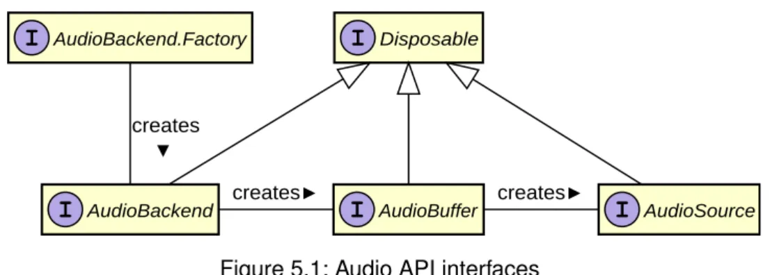
Figure 5.1: Audio API interfaces
version 19 [17]. Since the audio API is designed to be backwards-compatible with API version 10, using this interface is not an option. While theCloseableinterface exists since version 1 of the Android API, it is defined to throw anIOException, which is a checked exception [18]. Releasing the resources that may be in use by an audio API implementation should either be unable to fail or throw aRuntimeException, since a failure to release the resources might leave the audio API implementation in a non- recoverable state. Because of these reasons the audio API defines theDisposable interface (see Listing 5.3). It serves the same function as theAutoCloseableinterface, but is available on all supported Android API levels.
1 interface Disposable {
2 void dispose();
3 }
Listing 5.3: Disposable interface
5.2.2 Positional Audio API
The main part of the Positional Audio API are the interfaces that provide a generic method of accessing a positional audio framework. A realization of the API has to imple- ment theAudioBackend, theAudioBufferas well as theAudioSourceinterface.
The relationship between these interfaces can be seen in Figure 5.1. Since each of them may hold resources that need to be released, they all extendDisposable.
Before actually creating a positional audio source, first the chosen audio back-end has to be initialized. An audio back-end is represented by theAudioBackendinterface (see Listing 5.4). To create an instance of this class, a factory object should be used. This
5 Framework
1 public interface AudioBackend extends Disposable {
2 @Nonnull
3 AudioBuffer createBuffer(AudioData audioData);
4 void pauseAll();
5 void resumeAll();
6 float getOrientation();
7 void setOrientation(float azimuth);
8 float getGain();
9 void setGain(float gain);
10 }
Listing 5.4: AudioBackend interface
object should implement theFactorysubinterface of theAudioBackendinterface (see Listing 5.5). This interface defines a factory method to create an audio back- end instance [9]. Having a common factory interface is especially useful when using dependency injection. It allows an application or library to create an audio back-end without having to know its actual type. Thecreatemethod takes aContextobject as its only argument to allow the back-end to access Android system services or load assets [19]. If a back-end is not supported on a device the creation may fail by returning nullfrom the factory method. ThegetBackendNamemethod returns the name of the back-end created by this factory, it can for example be displayed when allowing the user to choose an implementation.
1 public interface AudioBackend extends Disposable {
2 interface Factory {
3 @Nonnull
4 String getBackendName();
5 @Nullable
6 AudioBackend create(Context context);
7 }
8 }
Listing 5.5: AudioBackend.Factory interface
Once created theAudioBackendprovides methods to get or set the listener orientation and the gain factor of the output. The orientation is given as a counter-clockwise rotation in radians. It also can pause and later resume all audio sources currently managed by the back-end. Finally, thecreateBufferfactory method can be used to create an audio buffer filled with the audio data provided as parameter.
5.2 Audio API
The created buffer implements theAudioBufferinterface (see Listing 5.6). It defines only one method: createSource. This factory method is used to create an audio source backed by this buffer. Multiple audio sources can be backed by the same buffer.
1 public interface AudioBuffer extends Disposable {
2 @Nonnull
3 AudioSource createSource();
4 }
Listing 5.6: AudioBuffer interface
The created audio sources implement theAudioSourceinterface (see Listing 5.7).
This interface defines methods to play or pause playback as well as a method to query if the source is currently playing. Stopping, that is pausing and resettings the playback position, is also supported. The source can be set to loop, it will then not stop playing when it reaches the end of the audio data buffer but instead restart playback from the beginning. The playback position can also be queried or set manually. Each source has its own gain factor that is applied in addition to the gain factor set by the back-end.
Finally, since this is a positional audio API, the position of the source can be set. It is set in polar coordinates as an angle and a distance. As with the listener, the angle is given as a counter-clockwise rotation in radians. The distance has no predefined unit, but if the distance is set to one unit or less, the amplitude gain factor of the source will
1 public interface AudioSource extends Disposable {
2 void play();
3 void pause();
4 void stop();
5 boolean isPlaying();
6 float getPositionAzimuth();
7 float getPositionDistance();
8 void setPosition(float azimuth, float distance);
9 boolean isLooping();
10 void setLooping(boolean looping);
11 float getGain();
12 void setGain(float gain);
13 int getPlaybackPosition();
14 void setPlaybackPosition(int position);
15 }
Listing 5.7: AudioSource interface
5 Framework
not be lowered because of the distance. If the distance is more than unit, the amplitude gain factor is calculated as the inverse of the distance (see Equation 5.1) [47]. The distance amplitude gain factor is applied in addition to the source amplitude gain factor.
If the distance of a source is set to zero it is an ambient source. The sound of such a source does not change with the orientation of the listener and is equally audible on all output channels.
gaindistance =
1 if|distance| ≤1
|distance|−1 if|distance|>1
(5.1)
5.2.3 Abstract Helper Classes
The audio API module also contains some abstract helper classes that assist with implementing the positional audio back-end interfaces. They are based on the ab- stractObservableDisposableclass (see Listing 5.8). This class implements the Observer pattern [9]. Observers of this class must implement theObserversubinter- face. They can then be registered using theaddObservermethod and removed using theremoveObservermethod. The class keeps a strong reference to each registered observer. The generic type parameterOspecifies the type of the class that extends this abstract class. Making the class and by extension theObserverinterface generic allows for theonDisposemethod to receive a reference to the disposed object using its actual type without needing any casts. ThenotifyDisposemethod should be called by the implementing class to notify any registered observers when the object is is being disposed.
1 abstract class ObservableDisposable
2 <O extends ObservableDisposable<O>>
3 implements Disposable {
4 interface Observer<O extends ObservableDisposable<O>> {
5 void onDispose(O disposable);
6 }
7 final void addObserver(Observer<O> observer);
8 final void removeObserver(Observer<O> observer);
9 final void notifyDispose(O observable);
10 }
![Figure 3.1: A PCM encoder and decoder [4]](https://thumb-eu.123doks.com/thumbv2/1library_info/5210958.1668898/18.892.170.726.115.299/figure-a-pcm-encoder-and-decoder.webp)

![Figure 3.12: A KEMAR dummy head with pinnae [61]](https://thumb-eu.123doks.com/thumbv2/1library_info/5210958.1668898/25.892.374.519.128.343/figure-a-kemar-dummy-head-with-pinnae.webp)
![Figure 3.13: Convolution using a separate FIR filter for each ear [2]](https://thumb-eu.123doks.com/thumbv2/1library_info/5210958.1668898/26.892.283.614.120.663/figure-convolution-using-separate-fir-filter-for-each.webp)