https://doi.org/10.1007/s00145-020-09346-z
Efficient and Scalable Universal Circuits
∗Masaud Y. Alhassan·Daniel Günther·Ágnes Kiss·Thomas Schneider
Technical University of Darmstadt, Darmstadt, Germany sophismay@gmail.com
guenther@encrypto.cs.tu-darmstadt.de kiss@encrypto.cs.tu-darmstadt.de schneider@encrypto.cs.tu-darmstadt.de
Communicated by Nigel Smart.
Received 28 March 2019 / Revised 18 February 2020 Online publication 8 April 2020
Abstract. A universal circuit (UC) can be programmed to simulate any circuit up to a given sizenby specifying its program inputs. It provides elegant solutions in vari- ous application scenarios, e.g., for private function evaluation (PFE) and for improving the flexibility of attribute-based encryption schemes. The asymptotic lower bound for the size of a UC is(nlogn), and Valiant (STOC’76) provided two theoretical con- structions, the so-called 2-way and 4-way UCs (i.e., recursive constructions with 2 and 4 substructures), with asymptotic sizes∼5nlog2nand∼4.75nlog2n, respectively.
In this article, we present and extend our results published in (Kiss and Schneider EUROCRYPT’16) and (Günther et al. ASIACRYPT’17). We validate the practicality of Valiant’s UCs by realizing the 2-way and 4-way UCs in our modular open-source implementation. We also provide an example implementation for PFE using these size- optimized UCs. We propose a 2/4-hybrid approach that combines the 2-way and the 4-way UCs in order to minimize the size of the resulting UC. We realize that the bot- tleneck in universal circuit generation and programming becomes the memory con- sumption of the program since the whole structure of sizeO(nlogn)is handled by the algorithms in memory. In this work, we overcome this by designing novel scalable algorithms for the UC generation and programming. Both algorithms use onlyO(n) memory at any point in time. We prove the practicality of our scalable design with a scalable proof-of-concept implementation for generating Valiant’s 4-way UC. We note that this can be extended to work with optimized building blocks analogously. More- over, we substantially improve the size of our UCs by including and implementing the recent optimization of Zhao et al. (ASIACRYPT’19) that reduces the asymptotic size of the 4-way UC to∼4.5nlog2n. Furthermore, we include their optimization in the implementation of our 2/4-hybrid UC which yields the smallest UC construction known so far.
Keywords. Universal circuit, Private function evaluation, Function hiding, Scalability.
∗This article is a combined and substantially extended version of [45] (EUROCRYPT’16) and [31]
(ASIACRYPT’17). We summarize the additional contributions in Sect.1.3.
© The Author(s) 2020
1. Introduction
Any computable Boolean function f(x)can be represented as a Boolean circuitCug,v(x) withu input wiresx =(in1, . . . ,inu),v output wires out1, . . . ,outv, andg gates for someu, v,g. The size of such a Boolean circuit isn =u+v+g. Universal circuits (UCs) are programmable circuits that can simulate any Boolean function f(x)up to a given sizen. To program a UC to compute f, programming or control bits are specified as further inputscf = {c1, . . . ,cm}. The UC then receives these control bits as inputs along with the inputxand computes the result asU C(x,cf)= f(x). This means that the same UC can evaluate different Boolean circuits by specifying the respective control bits. In analogy to a universal Turing machine, a universal circuit allows to turn any function into data in the form of a program description.
Several efficient constructions considering both the size and the depth of UCs were proposed. Valiant proposed in [66] an asymptotically size-optimal UC construction with size(nlogn)and depthO(n)[68]. He presents two constructions, called 2-way and 4-way UCs, based on so-called edge-universal graphs (EUGs) that utilize either 2 or 4 subcircuits, respectively. The asymptotic complexity of the 4-way UC is∼4.75nlog2n which is smaller than that of the 2-way UC of∼5nlog2n[66]. The 4-way UC has been further improved in [72], where its size is reduced to∼4.5nlog2n. An asymptotically depth-optimal construction with depth(d)that simulates circuits with depth d was proposed in [17], but it has a significantly larger size ofO(n3d/logn). In our paper, due to the applications in cryptography that we revisit in Sect.1.1, we concentrate on the existing size-optimized UCs, especially that proposed by Valiant [66] with asymptotic size(nlogn)with the optimization presented by Zhao et al. in [72].
1.1. Applications of Universal Circuits
Size-optimized universal circuits have many applications, which we review here and refer to the original publications for a more detailed description.
Private Function Evaluation (PFE)
The most prominent application of universal circuits is the secure evaluation of private functions based onsecure function evaluation(SFE) orsecure computation. SFE enables two partiesP1andP2to evaluate a publicly known function f(x,y)on their respective private inputs x and y, ensuring that none of the participants learns anything about the other participant’s input apart from the output of the computation. Many secure computation protocols, such as Yao’s garbled circuit protocol [47,69,70] and the GMW protocol [32], use Boolean circuits for representing the desired functionality. In some applications, the function itself should be kept private. This setting is calledprivate function evaluation(PFE), where we assume that only one of the partiesP1knows the function f(x), whereas the other partyP2provides the input to the private functionx.
P2should learn no information about f except for an upper bound on the size of the circuit describing the function, andP1should learn nothing aboutx beyond what can be inferred from the result f(x).
PFE can be reduced to SFE [1,44,58,63] by securely evaluating a UC that is pro- grammed by P1to evaluate the function f on P2’s inputx. For this, P1provides the control bitscf for the UC andP2provides his private inputxinto an SFE protocol that computesU C(x,cf). Here, the UC is a public function and the control bitscf—and therefore the function f—and inputxare kept private due to the properties of SFE. The first implementation of PFE was provided in [44,61], which extends the Fairplay secure computation framework [51] with universal circuits. The underlying UC construction achieves a non-optimal asymptotic size ofO(nlog2n)and depthO(nlogn). We have shown in [45] that it results in larger UCs than Valiant’s constructions for all reasonable circuit sizes in practice. The complexity of PFE in this case is determined mainly by the size and depth of the UC, while the security follows from that of the SFE protocol that is used to evaluate the UC. If the SFE protocol is secure against semi-honest, covert, or malicious adversaries, then the PFE protocol is secure in the same adversarial setting.
UC-based PFE can be easily integrated into any SFE framework and can directly benefit from recent optimizations. For instance,outsourcing UC-based PFEto two or multiple servers using XOR secret sharing is directly possible with outsourced SFE [42]. The non-interactive secure computation protocol of [3] can be generalized to obtain anon- interactive PFE protocol [46]. Moreover, with UC-based PFE, evaluating public and private parts of a functionality can easily be performed together without modifying the underlying secure computation framework.
In [40], Katz and Malka presented an alternative approach for PFE that does not rely on UCs. They use additively homomorphic public-key encryption as well as a symmetric- key encryption scheme and achieve constant-round PFE with linearO(n)communication complexity. However, the number of public-key operations is linear in the circuit size, and due to the gap between the efficiency of public-key and symmetric-key operations, this results in a less efficient protocol. Their protocol is secure against semi-honest adver- saries, uses Yao’s garbled circuits [70], and has recently been improved in [5], where the authors modify the algorithm to perform one full execution from which information can be reused in subsequent more efficient executions of the protocol. Mohassel and Sadeghian consider PFE with semi-honest adversaries in [53] and propose a generic PFE framework that can be instantiated with different secure computation protocols.
Their first protocol uses homomorphic encryption with which they achieve linear com- plexityO(n)in the circuit sizen and their second protocol relies solely on oblivious transfers (OT), which results in a method withO(nlogn)symmetric-key operations.
The OT-based construction from [53] or PFE using UCs is more desirable than the lin- ear homomorphic encryption-based methods in practice, since using OT extension, the number of expensive public-key operations can significantly be reduced, such that it is independent of the number of OTs [2,36]. Biçer et al. [6] improve the communication of the OT-based PFE protocol of [53] by around 40%. The asymptotic complexity of the OT-based construction of [53] and Valiant’s UCs for PFE is the same, and therefore, we compare these solutions for PFE in more detail in Sect.8. Mohassel et al. extend the framework from [53] to malicious adversaries in [54] with linear complexityO(n), using additively homomorphic encryption. Active security of UC-based PFE is achieved by using a secure computation protocol with active security. Even though their claimed better efficiency, to the best of our knowledge, these protocols have not yet been imple-
mented and are not as generally applicable as PFE with UCs, e.g., they cannot be easily combined with secure evaluation of public functions.
Semi-private function evaluation (semi-PFE) has been proposed in [60] and allows for PFE where the function f is in a set of functions F known by both parties. This relaxes the necessary topology hiding requirement of generic PFE. Yao’s garbled circuit can be used for evaluating circuits of the same topology as shown in [59]. Recently, an automated approach for semi-PFE has been proposed in [39], where the circuits representing f ∈ Fhave varying topologies, for which a container topology is found that can be programmed to compute any of the available topologies. This has therefore been defined as a set-universal circuit, i.e., a circuit that can be programmed to compute any circuit from a pre-defined set of circuits. This approach has been further improved in [41], where a modified garbled circuit protocol allows for efficient semi-PFE with linear communication in the size of the largest circuit inF. However, semi-PFE does not suffice for generic PFE where we have an exponential number of possible circuit topologies.
Applications of PFE
PFE can be applied in scenarios where one of the parties wants to keep the evaluated function private. One of the first applications for PFE wasprivacy-preserving checking for credit worthiness[21], where not only the loanee’s data, but also the loaner’s function that computes if the loanee is eligible for a credit needs to be kept private. The original scheme, using garbled circuits, can represent simple policies, but by evaluating a UC their scheme can be extended to more complicated credit checking policies. [15] shows an application for secure computation, where evaluating UCs or other PFE protocols would ensure privacy: Whenautonomous mobile agentsmigrate between several distrusting hosts, the privacy of the inputs of the hosts is achieved using SFE, while privacy of the mobile agent’s code can be guaranteed with PFE. [57] shows a method tofilter remote streaming dataobliviously, using secret keywords and their combinations. Their scheme can additionally preserve data privacy by using PFE to search the matching data with a private search function. PFE allows for runningproprietary softwareon private data, such as privacy-preserving evaluation of diagnostic programs that was considered in [13], where the owner of the program does not want to reveal the diagnostic method and the user does not want to reveal his data. Example applications for such programs include medical diagnostics [9] and remote software fault diagnosis, where the function and the user’s input are desired to be handled privately. In the protocol presented in [13], the diagnostic programs are represented as binary decision trees or branching programs which can easily be converted into a Boolean circuit representation and evaluated using PFE based on universal circuits. Moreover, PFE can be applied to createblinded policy evaluation protocols [20,24]. [20] utilizes UCs for so-called oblivious circuit policies and [18] for hiding the circuit topology in order to create one-time programs. In [25,59], universal circuits are used for hidingqueries in private database management systems(DBMSs). The Blind Seer DBMS [25] was improved in [59] by making use of a simpler UC for evaluating queries, which does not hide the circuit topology. The authors mention that in case the topology of the SQL formula and the circuit have to be kept private, a generic UC should be utilized. Further applications
of PFE given in [53] areevaluation of branching programs on encrypted data[37] and privacy-preserving intrusion detection[56].
UC Applications Beyond PFE
Apart from being used for PFE, UCs can be applied in various other scenarios. Efficient verifiable computationon encrypted data was studied in [22]. A verifiable computation scheme was proposed for arbitrary computations, and a UC is required to hide the function. [29] make use of UCs for reducing the verifier’s preprocessing step. In [30], a DDH-based multi-hop homomorphic encryption scheme is proposed that uses re- randomizable garbled circuits, for which UCs are used to achieve function privacy. When the common reference string is dependent on a function that the verifier is interested in outsourcing, then the function description can be provided as input to a UC of appropriate size. As described in [4], theAttribute-based encryption(ABE) schemes [27,34] for any polynomial-size circuits can be turned into ciphertext-policy ABE by using UCs. The ABE scheme of [28] also uses UCs. Universal circuits can be applied for program obfuscation. Candidates forindistinguishability obfuscationare constructed using a UC as a building block in [14,26]. The algorithm of [26] has been implemented in [12], which can be improved using Valiant’s UC implementation [45].Direct program obfuscation was proposed in [71], where the circuit is a secret key to a UC. [46] mentions that UCs can be applied for secure two-party computation in the batch execution setting, where the cost of evaluating Yao’s garbled circuits is amortized if the same circuit—a UC—is evaluated [35,49]. This protocol has been made round-optimal in [52].
Implied Theoretical Results
We mention two theoretical results relying on UCs. Both the depth-optimized UC from [17] and Valiant’s size-optimized UCs were adapted in [8] to constructuniversal quantum circuits. The design ofuniversal parallel computerswas inspired by Valiant’s UCs as well [33,50].
1.2. Our Contributions and Outline
In Sect.2, we recapitulate the necessary preliminaries for our work. We revisit the asymp- totically size-optimal UCs of [66] in Sect.3. This complex construction makes use of an internal graph representation and programs a so-called edge-universal graph (Sect.3.1).
Thereafter, we describe how an edge-universal graph can be translated into a universal cir- cuit (Sect.3.2). Finally, we revisit Valiant’s 2-way (Sect.3.3) and 4-way UCs (Sect.3.4) and the improved building block proposed by Zhao et al. [72] for the latter.
Our modular programming algorithm(Sect.4). We detail our modular algorithm for programming a universal circuit that provides the description of the input function f as program bitscf to the UC, for both Valiant’s 2-way and 4-way UCs. Our method consists of two steps, the block edge-embedding (Sect.4.1) and the recursion point edge-embedding (Sect.4.2).
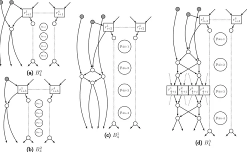
New universal circuit constructions and extensions (Sect. 5). We describe Lip- maa et al.’s generalization [46] of Valiant’s universal circuit to anyk-way UC (Sect.5.1) and detail how our modular programming algorithm from Sect.4can be directly gener-
alized for this extension. We continue with presenting a new 3-way UC (Sect.5.2) that is predicted to be more efficient than the existing UCs. However, after providing mod- ular building blocks for this UC, we show that it is asymptotically larger than Valiant’s UCs, due to an optimization that cannot be applied for one of its building blocks. Then, we propose a hybrid UC construction (Sect.5.3) that can efficiently combinek-way UCs for multiple values ofk. With this, we combine Valiant’s 2-way and 4-way UCs to achieve the smallest universal circuit known so far. Lastly, we provide our scalable algorithms (Sect.5.4) that allow for generating and programming UCs with only linear O(n)memory instead of handling the whole structure of sizeO(nlogn)in memory at once.
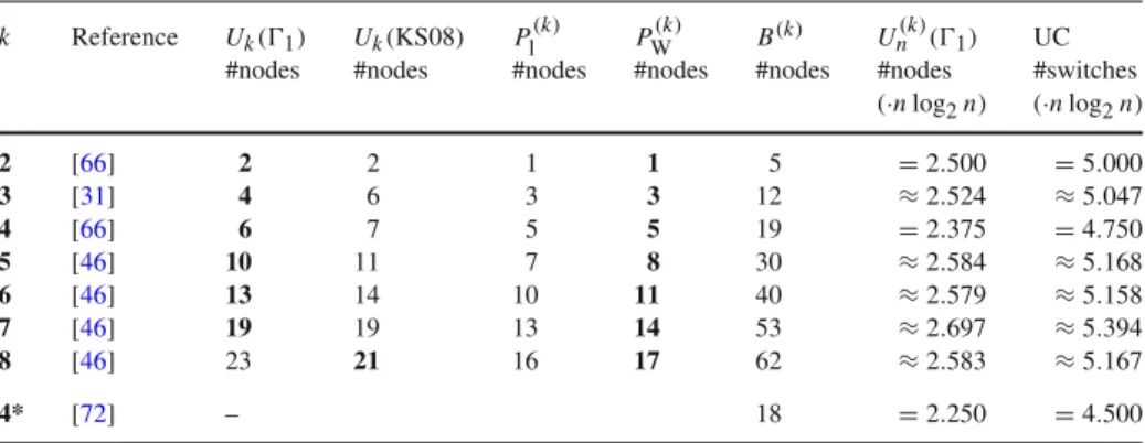
Optimized size and depth of UCs(Sect.6). We compare the asymptotic (Sect.6.1) and concrete (Sect.6.2) sizes of Valiant’s (2-way and 4-way) UCs and that of differentk-way UCs. We show that of allk-way UCs of Lipmaa et al. [46], Valiant’s 4-way UC provides the smallest size for large circuits, whereas Valiant’s 2-way UC provides the smallest depth. We include size optimizations, achieving a linear concrete improvement for all UCs. Moreover, we show that our 2/4 hybrid method for generating UCs improves over the 4-way UCs, i.e., both over Valiant’s 4-way UC and over the optimized 4-way UC of [72].
Implementation of Valiant’s UCs and experiments(Sect.7). We detail the steps of our algorithm for a practical realization of Valiant’s UC construction and implement the 2-way and recently optimized 4-way UCs as well as our 2/4 hybrid UC construction.
We note that our implementation is the first implementation that includes the optimiza- tion of Zhao et al. [72], which achieves the best size∼4.5nlog2nto date. We describe the architecture of our UC compiler (Sect.7.1). We experimentally evaluate the per- formance of our UC generation and programming algorithms with a set of example circuits (Sect.7.2). We provide the evaluation of our scalable 4-way UC as well and compare it with our memory-based implementation of Valiant’s 4-way UC.
Toolchain for private function evaluation using universal circuits(Sect.8). We provide the implementation of an example application for universal circuits, namely of private function evaluation (PFE) by extending the ABY secure function evaluation framework [19] to evaluate our universal circuits (Sect.8.1). We provide the first implementa- tion for PFE withO(nlogn)complexity and show experimental results for performing PFE (Sect.8.2). We theoretically compare PFE with UCs with other state-of-the-art approaches for PFE (Sect.8.3).
1.3. Additions to Conference Versions
This journal article is a significantly extended and improved version of the conference publications [45] and [31]. Our added contributions are as follows.
1. Optimizations.We included the optimized building block of [72] in our 4-way and hybrid implementations as well as in the size and depth comparisons. This allows us to compare all state-of-the-art methods for UCs. This is the first implementation of their construction, which has the lowest asymptotic and concrete sizes known so far.
2. Scalability.We extend our design and implementation with a scalable 4-way UC construction based on Valiant’s 4-way UC, which reduces the memory complexity fromO(nlogn)toO(n)when generating and programming the universal circuit.
This construction involves a novel layer-by-layer approach for generating and topologically ordering the universal circuit and programs the structure according to the recursion steps, i.e., subcircuit by subcircuit.
3. Universal circuit depths.We examine the depth of the universal circuits in addi- tion to their sizes, since though being optimized for the latter, some applications also require to minimize the former. For instance, the number of communication rounds in PFE via secure function evaluation with the GMW protocol [32]—
which in contrast to Yao’s garbled circuits allows to precompute all symmetric cryptographic operations [64]—depends on the depth of the universal circuit.
4. Comparison and implementation.In our previous works, we have compared the 2-way and 4-way UCs with each other and with the only other existing UC of [44]. In this work, we implement the hybrid method that uses both 2-way and 4-way UCs and achieves the best concrete size for all simulated circuit sizes. We also implement our new scalable 4-way UC construction, which utilizes very dif- ferent algorithms than those applied before for UC generation. We compare these methods with respect to runtime, communication, and memory consumption.
2. Preliminaries
As preliminaries for our paper, we introduce the graph and circuit theoretic background in Sect.2.1and Sect.2.2, respectively. We provide a summary of all our notations and abbreviations in “Appendix A.”
2.1. Graph Theory
In this section, we describe the graph theoretic preliminaries necessary for our work.
Definition 1. The number of incoming [outgoing] edges of a node is called itsindegree [outdegree]. A graph hasfanin [fanout]ρif the indegree [outdegree] of all its nodes is at mostρ.
We denote byρ(n)the set of all directed acyclic graphs withnnodes and fanin and fanoutρ.
Definition 2. LetG=(V,E)be adirected graphwith set ofnodes V = {1, . . . ,n}
andedges E ⊆V ×V. A mappingηG :V → {1, . . . ,n}is calledtopological order if(i,j) ∈ E implies that ηG(i) < ηG(j)and∀i,j ∈ V : ηG(i) = ηG(j)means thati = j. In short,i > j implies that there is no edge or directed path fromito j. A topological order ofG∈ρ(n)can be found with computational complexityO(ρn).
Further on, we require a labeling of the nodes in a topological order.
Definition 3. Edge-embedding is a mapping from graph G = (V,E) into G = (V,E)that mapsV intoVone-to-one, with possible additional nodes inV, i.e.,V ⊆ VandEinto directed paths inE, such that all paths are pairwise edge-disjoint, i.e., an edge can be used only in one path.
Theorem 1. (K˝onig–Hall theorem)Given a directed acyclic graph (DAG) G ∈2(n), the set of edges E can be separated into two disjoint sets E1 and E2, such that graphs G1 = (V,E1)and G2 = (V,E2)are instances of1(n), having fanin and fanout 1 for each node[38,48,66].
Proof of Theorem1. Given the set of nodes in topological orderV = {1, . . . ,n}, we can construct a bipartite graphG=(V,E)with nodesV = {m1, . . . ,mn,m1, . . . ,mn} and edgesE such that(mi,mj)∈ E if and only if(i,j)∈ E. It is easy to see that the fanin and fanout of the resulting bipartite graph is also 2. The edges ofGand thus the corresponding edges ofGcan be colored in a way that the result is a valid two-coloring.
Having fanin and fanout of at most 2, such coloring can be found directly with the following method:
1: whilethere are uncolored edges inGdo
2: Choose an uncolored edgee = (mi,mj)randomly and color the path or cycle that contains it in an alternating manner: The neighboring edge(s) of an edge of the first color will be colored with the second color and vice versa.
3: end while
This edge-coloring can be performed inO(n)steps and it defines the edges inE1andE2, such thatE1contains the edges colored with color one and E2the ones with color two
andG1=(V,E1)andG2=(V,E2).
The K˝onig–Hall theorem was used in [45,46] to provide a 2-coloring algorithm for the edges of a graph with fanin and fanout 2. In its originally proposed form, however, K˝onig’s theorem [38,48] applies also for k-coloring the edges of any graph with at mostkincoming and outgoing edges for each of its nodes. This transformation can be easily generalized to graphs ink(n), in which case the resulting bipartite graph will have fanin and fanoutk. We review this theorem and the corresponding algorithm here.
Theorem 2. (K˝onig’s theorem)If G is bipartite and its nodes have at most k incoming and outgoing edges, then the number of colors sufficient to color all edges of G is k.
Proof of Theorem2. ([38,48]) Take colors{1, . . . ,k}, and greedily color edges. Let us assume that at some point the coloring stops because we cannot color more edges. In this step,(wi,zj)is an uncolored edge. If we look at the colors of the edges adjacent towi andzj, we can define the set of available colors for both nodes. There is at least one color for both wiandzjdue to the fanin and fanout restriction, but there is no color which is available for both nodes, otherwise we could color(wi,zj).
There is a color that is used in an edge adjacent towi, e.g., colora, but not on an edge adjacent tozj. In the same way, we can find another colorbthat is used in an edge
adjacent tozj, but not towi. Take the longest unique path Pfromwi that uses colorsa andbalternatingly.
Indirectly, assume that this path also containszj. It then terminates inzj due to the fact thatzj is not adjacent with an edge colored witha. Then,P ∪(wi,zj)is an odd cycle, which is impossible sinceGis bipartite. Therefore,pdoes not containzj, and we can exchange colorsaandbon path Pand color(wi,zj)with colora.
This process is continued until there are no uncolored edges inG.
2.2. Circuit Theory
Definition 4. Thefanin [fanout]of a circuit can be defined analogously to the fanin [fanout] of a graph (cf. Definition1), i.e., the maximum number of incoming [outgoing]
wires of all its gates, inputs and outputs.
Theorem 3. A circuit Cugˆ,v with u inputs, g gates, andˆ v outputs and fanin and fanoutρ >2can be transformed to a circuit Cug,vwith fanin and fanout 2.
Proof of Theorem3. Shannon’s expansion theorem [61,62] describes how gates with larger fanin can be reduced to gates with two inputs by adding additional gates, which results in a circuitCug˜,vwithg˜fanin 2 gates. It was proven in [66] that the general case, where the fanout of the circuit can be any integerρ ≥ 2, can be transformed to the special case whenρ≤2 by introducing copy gates, each of which eliminates one from the extra fanout of the original gate. We place a binary tree in place of each gate with fanout larger than 2, following Valiant’s proposition:„Any gate with fanout x+2can be replaced by a binary fanout tree with x+1gates”[66, Corollary 3.1]. Thus, the class of Boolean functions withuinputs andvoutputs that can be realized by acyclic circuits withg˜ gates and arbitrary fanout can also be realized with an acyclic fanout-2 circuit withg˜ ≤g≤2g˜+vgates.
Definition 5. We can regardCug,v withu inputs, v outputs, and g gates as a 2(n) graphG—which we commonly refer to as thegraph of circuit Cug,v—withn=u+v+g by creating a node for each input, gate, and output, and an edge for each wire inCug,v.
3. Valiant’s Universal Circuit Constructions
In any circuitCugˆ,v, the inputs of each of thegˆgates are either connected to one of the uinputs, to the output of a previous gate, or are assigned a fixed constant. Due to the nature of Valiant’s edge-universal graph (EUG) construction, the input circuit must have fanin and fanout 2, which can be achieved with the transformations described in Sect.2.2 and implemented in [44,45]. From here on, and without loss of generality, we assume that our input circuitCug,vhasuinputs,ggates andvoutputs and fanin and fanout 2.
The size of a function f represented by a circuitCug,v with fanin and fanout 2 is n = u +v +g, which can be represented as a graph G ∈ 2(n). In this section, we describe Valiant’s UC constructions [66,68] that can be programmed to evaluate
any function of sizen. We explain the general idea behind Valiant’s UC construction [66] in Sects.3.1and3.2, and the 2-way and 4-way UCs along with improvements of [31,45,46,72] in Sects.3.3and3.4, respectively.
3.1. Valiant’s Edge-Universal Graph Construction
Valiant’s UC construction relies on the notion of so-called edge-universal graphs that are then translated to universal circuits [66].
Definition 6. A graph Un(ρ) = (VU,EU)is anedge-universal graph (EUG) for ρ(n)if every graph G =(V,E)inρ(n)can be edge-embedded (cf. Definition3) intoUn(ρ).
An EUGUn(ρ) has distinguished nodes calledpoles P = {p1, . . . ,pn} ⊆ VU
where each nodea ∈ V = {1, . . . ,n}is mapped to exactly one pole with an injective mappingϕV : V → VU. This mapping is defined by a concrete topological orderηG of the original graphGwithϕV(a)=pηG(a), i.e., every node inGhas a corresponding pole inUn(ρ). Apart from the poles,Un(ρ)might have additional nodes that enable the edge-embedding (cf. Sect.2.1). For each edge(ai,aj)∈ E, we then define a path of variable length z between the corresponding poles ϕV(ai) = pηG(ai) = b1 and ϕV(aj)= pηG(aj) = bz as(b1, . . . ,bz), whereb1, . . . ,bz ∈ VU. All these paths are edge-disjoint, i.e., they do not use any edge inUn(ρ)in more than one path (cf. Sect.2.1).
LetUn(1)be an EUG for graphs in1(n)withnpolesP= {p1, . . . ,pn}(we will show concrete constructions for such EUGs in Sect.3.3and in Sect.3.4). The nodes of any topologically ordered1(n)graph can be mapped to these poles. The poles have fanin and fanout 1, while all other nodes have fanin and fanout 2.
An EUGUn(ρ)forρ ≥ 2 is created by takingρinstances ofUn(1)EUGs with polesP1= {p1,1, . . . ,p1,n}, . . . ,Pρ = {pρ,1, . . . ,pρ,n}, and merging each pole with its multiple instances, i.e., the set of merged poles P = {p1, . . . ,pn}is formed by mergingp1,1, . . . ,pρ,i to obtainpifori =1, . . . ,n. All edges are preserved, and thus, the poles have fanin and fanoutρ, i.e.,Un(ρ)=(VU,EU)is an EUG with fanin and fanoutρ, constructed withUn(1)1=(V1,E1), . . . ,Un(1)ρ =(Vρ,Eρ).Pcontains the merged poles andVU = P∪ρi=1Vi\PiandEU = ∪ρi=1Ei. Thus, the poles inUn(ρ) have at mostρinputs and outputs, and all other nodes have at most two inputs and outputs.
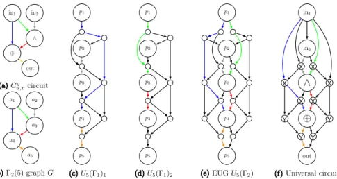
Example.LetC be the circuit shown in Fig.1a, and G = (V,E)be the graph of circuitCwith 5 nodes shown in Fig.1b. Our aim is to edge-embedGinto EUGU5(2). Therefore, we use two instances ofU5(1):U5(1)1in Fig.1c andU5(1)2in Fig.1d.
The edges(a1,a4), (a2,a3)and(a4,a5)are embedded inU5(1)1, and the edges(a1,a3) and(a3,a4)inU5(1)2. Merging the poles ofU5(1)1andU5(1)2producesU5(2) shown in Fig.1e. In Sect.3.2, we describe how to retrieve the resulting universal circuit depicted in Fig.1f.
Recursion Base.Valiant’s construction is recursive, and the recursion base graphs for up to 6 nodes are shown in [66, Fig. 3] and [45, Fig. 1].U1(1)is a single pole and U2(1)andU3(1)are two- and three-connected poles, respectively. Valiant provides hand-optimized EUGs forU4(1),U5(1)andU6(1), with 3, 7, and 9 additional nodes, respectively (cf. [66, Fig. 3]).
Fig. 1. aAn example circuit andbthe corresponding2(5)graphG.c,dThe edge-embedding ofGinto twoU5(1)instances with poles(p1, . . . ,p5).eThe edge-embedding ofGinto theU5(2)graph of the universal circuit shown in (f).
3.2. Translating Edge-Universal Graphs into Universal Circuits
In this section, we define universal circuits (UCs) and describe how an edge-universal graph is translated into a universal circuit.
Definition 7. Auniversal circuit U Cis a Boolean circuit that can be programmed to compute any circuitCug,vup to a given sizenby defining a set of programming bitscf such thatU C(x,cf)=Cug,v(x).
In Valiant’s UC constructions, every nodew ∈ VU fulfills a task whenUn(2)is translated to a UC. Programming the UC means specifying its control bits along the paths defined by the edge-embedding and by the gates of circuitCug,v. Depending on the number of incoming and outgoing edges and its type, a nodewis translated as described below and shown in the example in Fig.1f.
G1 Ifwis a pole and corresponds to an input (one of the firstu poles) or an output (one of the lastvpoles) inG, thenwis aninput or outputinCug,v as well.
G2 Ifwis not a pole and has indegree 1 and outdegree 2, this node has been placed to copy its input to its two outputs. Therefore, when translated to a UC,wis replaced by multiple outgoing wires in the parent node (as described in [45]), since the UC does not need to fulfill the fanout 2 restriction. InUn(2),wis added due to the fanout 2 restriction in the EUG necessary for the edge-embedding.
G3 Ifwis not a pole and has indegree and outdegree 1,wis removed and replaced by a wire between its parent and child nodes.
G4 If w is a pole and corresponds to a gate (poles {u +1, . . . ,u +g}) in G,w is programmed as auniversal gate(UG). A 2-input UG supports any of the 16 possible gate types represented by 4 control bits of the gate table(c1,c2,c3,c4).
Fig. 2.Programmable switching blocks [43].
It implements functionU:{0,1}2× {0,1}4→ {0,1}that computes
U(x1,x2,c1,c2,c3,c4)=x1x2c1+x1x2c2+x1x2c3+x1x2c4. (1) G5 If w is not a pole and has indegree and outdegree 2, w is programmed as an X-switching block, which computes X : {0,1}2× {0,1} → {0,1}2 with X((x1,x2),c)=(x1+c,x2−c)as shown in Fig.2a. The inputs of an X-switching block are forwarded to its outputs, switched or not switched, depending on control bitc.
G6 Ifwis not a pole and has indegree 2 and outdegree 1,wis programmed as aY- switching blockthat computesY : {0,1}2×{0,1} → {0,1}withY((x1,x2),c)= x1+c as visualized in Fig.2b. The inputs of a Y-switching block are forwarded to its output depending on the control bitc, i.e., it provides the functionality of a 2-input multiplexer.
We note that theuinputs and thevoutputs can be ordered arbitrarily within themselves as long as the inputs are kept before theg topologically ordered gates and the outputs after them. Even though the output nodes cause an overhead in Valiant’s UC, they are required to fully hide the topology of the circuit in the corresponding universal circuit.
Note that optionally it is possible to modify the input circuit such that the outputs of the lastvgates in order are the outputs of the circuit by inserting at mostvcopy gates [40].
The nodes programmed as UG (G4), X-switching block (G5), or Y-switching block (G6) are so-called programmable blocks. This means that a control bit c or vec- torc=(c1,c2,c3,c4)is necessary aside from the two inputs to define their behavior.
The universal gates are programmed according to the simulated gates inCug,v and the universal switches according to the paths defined by the edge-embedding of the graph of the circuitGinto the edge-universal graphUn(2). Depending on whether the path takes the same direction during the embedding (e.g., arrives from the left and continues on the left) or changes its direction at a given node (e.g., arrives from the left and con- tinues on the right), the control bit of the universal switch is programmed accordingly.
In Sect.7.1, we describe efficient implementations of programmable blocks. All control bits and vectors together are the programmingcf of the UC.
3.3. Valiant’s 2-way UC Construction
We described in Sect. 3.1that a Un(ρ) EUG can be constructed of ρ instances ofUn(1)EUGs. Valiant [66] provides an EUG for 1(n)graphs, two of which can
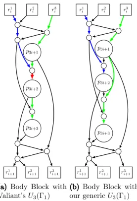
Fig. 3.Body blockB(2)of Valiant’s 2-way EUGUn(2)(1)[66].
build an EUG for2(n)graphs, which suffices for circuits with 2-input gates that have at most two outgoing wires. Let P = {p1, . . . ,pn}be the set of poles inUn(1)that have indegree and outdegree 1, corresponding to the inputs, gates and outputs of the input circuitCug,v, i.e., poles Pin = {p1, . . . ,pu} correspond to the inputs, Pgate = {p(u+1), . . . ,p(u+g)}to the gates,Pout= {p(u+g+1), . . . ,pn}to the outputs. The main, so-calledbody block B(2)used for constructing Valiant’s EUG for1(n)graphsUn(2)(1) of size∼2.5nlog2nis shown in Fig.3and consists of 2 poles (large circles), 4 so-called recursion points (rectangles), and 3 additional nodes (small circles). The corresponding UC has twice the size∼5nlog2n, since it corresponds to an EUG for2(n)graphs.
This construction is called the2-way EUG or UC constructionsince there are two sets of recursion nodes at each recursion step as we describe below.
The recursive construction works as follows: The rectangles are special nodes that build up the set of poles in the next recursion step, i.e., R1n
2−1 = {r11, . . . ,r1n 2−1} and R2n
2−1 = {r12, . . .r2n
2−1} are the poles of two smaller edge-universal graphs called subgraphs. EUGs are built with these poles which produce new subgraphs with sizen2−21 −1, such that we have four subgraphs at the next level, etc. The blocks are chained together at the recursion points to form a skeleton, i.e., each recursion point belongs to two in the corresponding subgraph. Thus, the main skeleton of the UC con- sists ofn2such blocks with poles{p1,p2, . . . ,pn}, and the next two skeletons consist ofn2−21blocks with sets of poles{r11, . . . ,r1n
2−1}and{r12, . . .r2n
2−1}. We visualize the process of chaining the blocks together to form this skeleton in Fig.4.
We note that the top (resp. bottom) block of a skeleton does not need the upper (resp. lower) recursion points since its poles are the inputs (resp. outputs) in the block.
Therefore, we presented optimized so-called headH(2)and tailT(2)blocks that occur in the top and bottom of a skeleton, respectively, in [31, Fig. 2b–e].
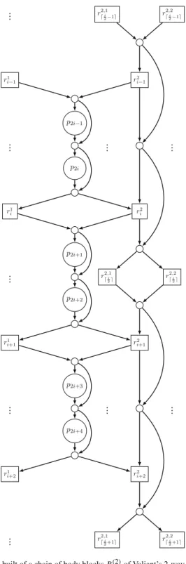
Fig. 4.Skeleton built of a chain of body blocksB(2)of Valiant’s 2-way EUGUn(2)(1).
Theorem 4. ([66]) The resulting 2-way EUG is edge-universal, and therefore, the resulting circuit is universal.
Proof of Theorem4[Val76]. We recapitulate the proof from [66] thatUn(2)(1)is edge- universal for1(n), such that any graph withn nodes and fanin and fanout 1 can be edge-embedded intoUn(2)(1). According to the definition of edge-embedding, it has to be shown that given any1(n)graphG=(V,E), for any(i,j)∈Eand(k,l)∈ Ewe can find pairwise edge-disjoint paths frompi topj and frompkto pl inUn(2)(1). As before, the labeling of nodesV = {1, . . . ,n}inGis according to a topological order of the nodes.
Firstly, each two neighboring poles of the EUG,p2s andp2s+1fors∈ {1, . . . ,n2}, are thought of as merged poles, so-called superpoles, with their fanin and fanout becom- ing 2. In a similar manner, anyG ∈ 1(n)graph can be regarded as a2(n2)graph with supernodes, i.e., each pair(2s,2s+1)will be merged into one node in a2(n2) graphG=(V,E). If there are edges between the nodes inG, they are simulated with loops. The set of edges of this graphGis partitioned to disjoint setsE1andE2, such that G1=(V,E1)andG2=(V,E2)are instances of1(n2)and1(n2), respectively.
This can be done efficiently, as shown in Theorem1. The edges in E1are embedded as directed paths inR1n
2−1, and the edges inE2as directed paths in R2n
2−1. BothE1
andE2have at most one edge directed into and at most one directed out of any supern- ode, and therefore, there is only one edge from E1 and one from E2 to be simulated going through any superpole inUn(2)(1)as well. Thus, the edge coming into a superpole (p2s,p2s+1)inE1is embedded as a path throughrs1−1, while the edge going out of the pole inE1is embedded as a path throughrs1in the appropriate subgraph. Similarly, the edges in E2are simulated as edges throughrs2−1 andrs2. These paths can be chosen disjoint according to the induction hypothesis. Finally, the paths fromrs1−1andrs2−1to superpole(p2s−1,p2s)as well as the paths from(p2s−1,p2s)tors1andrs2can be chosen edge-disjoint due to the skeleton built up of the body blocks shown in Fig.3. With this, Valiant’s graph construction results in a valid EUG with asymptotically optimal size O(nlogn)and depthO(n)[66]. With the building blocks described in Sect.3.2, it is easy to see that the resulting Boolean circuit is universal.
Implementation.We provided an open-source implementation of this 2-way UC opti- mized for PFE in [45]. In concurrent and independent related work, Lipmaa et al. [46]
also showed the practicality of Valiant’s 2-way UC. They decrease its total number of gates compared to that of Valiant’s block (Fig.3) by one XOR gate. However, the number of AND gates is exactly the same, and therefore, their improvement does not affect PFE using UCs, where XOR gates are evaluated for free [44].
3.4. Valiant’s 4-way UC Construction
Similarly to the 2-way EUG construction (cf. Sect.3.3), Valiant provides a more effi- cient4-way EUG or UC construction [66] for 1(n)graphs which can be extended to an EUG for2(n)graphs by utilizing two instancesUn(4)(1)1 andUn(4)(1)2 as described in Sect.3.1.Un(4)(1)has a 4-way recursive structure, i.e., at each recur-
Fig. 5. Body blockB(4)alternatives for 4-way EUGUn(4)(1).
sion step, nodes in special setsR1n
4−1 = {r11, . . .r1n
4−1},R2n
4−1= {r12, . . .r2n 4−1}, R3n
4−1 = {r13, . . .r3n
4−1}and R4n
4−1 = {r14, . . .r4n
4−1}1are the poles in the next recursion step (the main body block is shown in Fig.5a). The recursion base is the same as for the 2-way UC construction described in Sect.3.1. This construction results in UCs of smaller size∼4.75nlog2nbut has a more complicated structure and programming algorithm. We have studied and implemented this universal circuit in [31] and recapit- ulate our results here and in Sect.7. Valiant offers the main, so-calledbody block B(4) consisting of 4 poles (large circles), 15 nodes (small circles) as well as 8 recursion points (rectangles) shown in Fig.5a. As before, we provide so-calledhead H(4)andtail T(4) blocksthat occur at the top and bottom of a skeleton in [31, Figs. 4b-4i], respectively.
The blocks are connected such that the 4 top (resp. bottom) recursion points of one block are the 4 bottom (resp. top) recursion points of the next block. Similarly to the 2-way EUG, 4 sets are created fornnodes, i.e.,R1n
4−1,R2n
4−1,R3n
4−1, andR4n
4−1which are the poles of 4Un
2−1(1)EUGs in the next recursion step. Then, these also create 4 subgraphs until the recursion base is reached (cf. Sect.3.1).
1n (mod 4)of these have sizen4−1, but for the sake of simplicity, we do not distinguish these here.
Recently, Zhao et al. in [72] optimized the body block of Valiant’s UC by finding a more efficient block using exhaustive search over all possible blocks. As opposed to Valiant’s UC that uses 15 additional nodes in the body block, their block uses only 14 additional nodes, and therefore, their UC achieves an asymptotically better size of
∼4.5nlog2n. We depict the further optimized body blockB(4)of Zhao et al. in Fig.5b.
Zhao et al. provide a computer generated proof of that this block can indeed be used to construct universal circuits. Moreover, they show that there exists no block with only 13 additional nodes that can be used to construct UCs in the same manner. This proves that the minimal size of a 4-way UC is the achieved∼4.5nlog2n.
Theorem 5. ([66]) The resulting 4-way EUG is edge-universal, and therefore, the resulting circuit is universal.
The proof of this theorem is analogous to that of Theorem4.
4. Programming Valiant’s Universal Circuits
We designed the detailed embedding algorithm and the open-source UC implementation of [45] specifically for the 2-way UC, dealing with the whole UC skeleton as one block. In contrast, based on the modular design of [46], we modularized the edge-embedding task into multiple subtasks and described how they can be performed separately in [31]. In this section, we detail this modular approach for edge-embedding a graph into Valiant’s -way EUG, where=2 or =4: The edge-embedding can be split into two parts, which are then combined.
In the following, we describe the two main steps of our modular approach pre- sented in [31] that are based on the edge-embedding algorithm of [45]. 1) Block edge- embedding (Sect.4.1) allows for the programming of the blocks visualized in Fig.3on p. 12 and in Figs.5a or b on p. 14.2) Recursion point edge-embedding (Sect.4.2) takes care of the programming of the whole UC. Here, the paths are defined and the necessary information is provided to the blocks (cf. Sect.4.2). The process can be generalized to any 2i-way EUG. Moreover, the same modular edge-embedding algorithm can be applied with a few modifications for Lipmaa et al.’s generalization to anyk-way UC [46], which we describe later in Sect.5.1.
4.1. Block Edge-Embedding
We consider thetop (resp. bottom) recursion points of a block (Figs.3and5a or b) as intermediate nodes where the inputs (resp. outputs) of the block enter (resp. exit). The blocks are built so that any of these inputs can be forwarded to exactly one of thepoles of the block and the output of any pole can be forwarded to an output or another pole with a higher topological order.
We formalize this behavior as follows: In Un()(1) = (VU,EU), let B() be the (i −1)th block in the skeleton made up of blocks visualized in Fig.3for =2 and Fig.5a or b for=4 with poles pi+1, . . . ,pi+. Let the mappingηU : VU → N+ denote a topological order of all nodes and poles inVU. Then, the nodesri1, . . . ,riand
![Fig. 2. Programmable switching blocks [43].](https://thumb-eu.123doks.com/thumbv2/1library_info/5276903.1675798/12.659.86.579.76.197/fig-programmable-switching-blocks.webp)
![Fig. 3. Body block B ( 2 ) of Valiant’s 2-way EUG U n ( 2 ) ( 1 ) [66].](https://thumb-eu.123doks.com/thumbv2/1library_info/5276903.1675798/13.659.283.375.74.336/fig-body-block-b-of-valiant-way-eug.webp)

![Fig. 6. k-way EUG construction U n (k) ( 1 ) [46].](https://thumb-eu.123doks.com/thumbv2/1library_info/5276903.1675798/22.659.95.566.73.200/fig-k-way-eug-construction-u-n-k.webp)