Research Collection
Master Thesis
Pushing the Internet to the Edge
Author(s):
Schnider, Raphael Publication Date:
2020-02-10 Permanent Link:
https://doi.org/10.3929/ethz-b-000401663
Rights / License:
In Copyright - Non-Commercial Use Permitted
This page was generated automatically upon download from the ETH Zurich Research Collection. For more information please consult the Terms of use.
ETH Library
Pushing the Internet to the Edge
Master Thesis
Raphael Schnider sraphael@student.ethz.ch
Computer Engineering and Networks Laboratory
Department of Information Technology and Electrical Engineering ETH Z¨urich
Supervisors:
Romain Jacob Andreas Biri Prof. Dr. Lothar Thiele
February 10, 2020
Acknowledgements
I want to express my deepest gratitude towards Romain Jacob and Andreas Biri who supported me during my master thesis with their in-depth knowledge about technology and methodology and invested a lot of time to share it with me. Our discussions enriched this thesis and made me constantly strive for improvements.
I also want to thank Prof. Dr. Lothar Thiele for the opportunity to write my master thesis with the Computer Engineering group of ETH Zurich.
Further, I also want to thank the administrative staff of the TEC group for assisting me with technical and administrative problems. This thesis would not have been possible without the support of everyone mentioned here.
i
Abstract
In recent years the trend has been to connect any device to the internet to remotely sense or actuate objects, a concept called “Internet of Things”. Fore- casts predict billions of devices to be deployed and connected in the coming years.
To make such large scale deployments feasible, existing network infrastructure has to be reused as much as possible. The IP protocol is essential for todays internet and therefore must be supported by IoT devices to provide connectiv- ity with traditional internet-capable devices. However applying the traditional TCP/IP stack to those networks is a challenge because they must typically op- erate with constrained resources. To achieve IP connectivity within low-power wireless multi-hop networks (WSN), current industry standards rely on rout- ing within the WSN. Such routing-based networks have been shown to perform poorly in scenarios with mobile devices. An IoT network stack which supports reliable webservice-like interactions between traditional internet-capable devices and mobile IoT devices is needed.
Synchronous transmissions based on Glossy offer promising performance for mo- bile scenarios: 1. up to 99.99 % reliability, 2. fast network floods, 3. great mobility support because no topology-dependent state is present. This the- sis proposes to leverage the mobility support of synchronous transmissions and combine it with the flexibility of IP in an application-independent way. In this document the design and implementation of a proof-of-concept of such a network stack is presented. This stack shows a much improved mobility support com- pared to RPL, the routing protocol used by most current IoT standards. These results should motivate further research in synchronous transmissions for IoT which will hopefully lead to a standardized general-purpose protocol.
ii
Contents
Acknowledgements i
Abstract ii
1 Introduction 1
1.1 Motivation . . . 2
1.2 Application Scenario . . . 3
1.3 Goals . . . 3
1.4 Challenges . . . 4
1.5 Outline . . . 5
2 Background 6 2.1 Synchronous Transmissions . . . 6
2.2 CoAP . . . 7
2.3 6LoWPAN . . . 8
2.4 Related Work . . . 9
3 Design 10 3.1 Extending IP to the Edge . . . 10
3.2 Network Architecture . . . 11
3.2.1 Network Stack . . . 11
3.2.2 Network Components . . . 14
3.2.3 Modular Hardware . . . 16
3.3 Information Exchange . . . 17
3.3.1 Establishing Connectivity . . . 17
3.3.2 Enable Interaction . . . 20
iii
Contents iv
4 Implementation 23
4.1 Constrained Node . . . 23
4.1.1 APP Board . . . 23
4.1.2 COM Board . . . 24
4.1.3 Bolt . . . 25
4.2 Edge Router . . . 25
4.2.1 Baseboard . . . 26
4.3 Directory Server . . . 26
4.4 User . . . 27
4.5 IP Tunnel . . . 27
5 Evaluation 28 5.1 Experiment Setup . . . 28
5.1.1 Topology . . . 28
5.1.2 Traffic . . . 28
5.2 Experiment Results . . . 32
5.3 Mobility Comparison to Industry Standards . . . 36
5.4 Demonstration . . . 37
6 Conclusion 40 6.1 Findings . . . 40
6.2 Future Work . . . 41
7 Appendix 43 7.1 Online Resources . . . 43
Introduction
Since the first exchange of emails in the early 1970s electronic message passing has always been the focus of computer networks. The traditional TCP/IP stack was developed in the 1980s with the goal to connect mainframe computers through wired connections [1]. However in recent years the trend has been to connect any device to the internet, a concept called the “Internet of Things”
(IoT). This offers the benefit of being able to remotely sense or control objects using existing network infrastructure [2]. The “thing” in this context includes a wide variety of devices and applications such as smart city, smart surveillance, automated transportation, energy management, water distribution, environ- mental monitoring and many more [3]. These devices are typically small in size and constrained in their resources such as energy, memory and processing power. They require a wireless connection to make large-scale deployments in potentially remote, hard to access or mobile scenarios feasible.
A suitable network stack for those constrained devices aims at maximizing the performance while still satisfying the constraints. Multiple performance metrics such as power consumption, reliability, latency, stability, throughput and more exist which are most often in conflict with each other. The metrics which should be optimized depend on the application. As the traditional TCP/IP stack was not designed with these requirements in mind, adapting it to the IoT has a few challenges [1].
The essential layer of the protocol stack is the IP layer. It is the glue that holds the internet together, providing end-to-end connectivity between two arbitrary devices connected to the internet [4]. To provide translation between traditional IP based networks and constrained wireless sensor networks (WSN), early approaches for IoT stacks employed a gateway. These gateways remove the IP layer before forwarding the data to the constrained node. Such a translation can help to ease the burden on constrained devices. However similar to the translation of human language, certain information is lost and the network looses flexibility and does not support arbitrary IP packets but is
1
1. Introduction 2 instead speciallized to a certain application.
Standards for IoT network stacks developed in recent years rely on the “Rout- ing Protocol for Low-Power and Lossy Networks” (RPL) [5] to deliver IPv6 pack- ets within a multi-hop WSN. The “IPv6 over Low-Power Wireless Personal Area Networks” (6LoWPAN) adaption layer [6] is used to bridge the gap of link layer frames not supporting big enough messages for IPv6. However it has been shown that RPL networks perform poor in scenarios with mobile nodes [7]. Routing protocols must have some knowledge about the topology of the network which will inherently lead to challenges with mobile nodes. The work presented in this document explores the possibility of an IoT network stack that does not depend on routing within the WSN.
1.1 Motivation
The rising interest in IoT can be demonstrated by a Google Scholar search for the keyword “IoT”: 5050 results from 2008, 12800 results from 2013 and 133000 results from 2018. An important factor is the constant improvement of hardware which allows constrained devices to operate with more memory and processing power which enables them to run more complex protocols, making the IoT a reality.
Synchronous transmissions is a research area that emerged in recent years, trig- gered by the development of Glossy [8] which inspired a multitude of synchronous transmissions protocols [9]. They allow the delivery of messages between two nodes in a wireless multi-hop network without the use of a routing protocol.
Evaluations have shown promising performance results of high reliability up to 99.99% as well as latencies approaching the theoretical lower bound [8]. The main functional advantage over routing-based approaches based on RPL is the support of mobile nodes. Mobility can be of significance for example in a factory environment with sensors mounted to moving parts or wearable electronics which stay connected even as the wearer moves. RPL was not designed with mobile nodes in mind and evaluations have shown that the performance is degraded sev- erly in mobile scenarios [7]. Several modifications of RPL have been proposed specifically aimed at improving the mobile performance, such as Co-RPL [10]
and mRPL [11]. In contrast synchronous transmissions based protocols support node mobility without any extra effort by nature of their design: messages are flooded in the subnet and no topology-dependent state is present. It has been shown that using LWB [12], a synchronous transmissions protocol, as a link layer protocol a similar TCP throughput can be achieved for static and mobile sce- narios [13].
The good performance of synchronous transmissions and the inherent support for node mobility motivates the design of a proof-of-concept of an IPv6 capable
network stack using synchronous transmissions on the link layer. This enables direct interaction between a connected computer running a standardized network stack and a constrained node in a WSN which can take advantage of the benefits of synchronous transmissions.
1.2 Application Scenario
This document focuses on the following application scenario, which will influence the design and implementation of the network stack as well as the test scenarios used for the evaluation:
• Messages are exchanged primarily between a traditional, internet-capable device such as a server and constrained nodes. The philosophy behind this traffic pattern is to have minimalistic functionality on the constrained nodes, which perform a sensing or actuating task upon request. The server can then run arbitrarily complex computations to trigger actuations based on responses to sensing requests. The basic sensing and actuating func- tionalities of the constrained nodes are unlikely and infrequent to change, and a new algorithm to change the logic of actuations based on sensing only requires an update of the server software without the need to change the software running on the constrained nodes.
• The constrained network is a low-power multi-hop network and messages are only infrequently exchanged. Therefore the achievable throughput of the constrained network is of less interest compared to the success rate and delay of single messages within an otherwise silent network.
• Nodes are mobile only within the same constrained network.
• Packets are typically smaller than the maximum size of a wireless packet, which is 127 byte for IEEE 802.15.4 [14]. However IP packets arriving at the edge router can have a size of up to 1280 byte.
• Following the philosophy of having “dumb” nodes and centralized intelli- gence, nodes do not perform any action on their own (after the connectivity is established) but only react to received requests, typically by performing an action and sending a response back.
1.3 Goals
The proof-of-concept presented in this thesis has the following goals:
• Design and implementation of a fully IPv6-capable networking stack which uses synchronous transmissions inside a WSN.
1. Introduction 4
• The network does not have an application-specific gateway. The layered architecture guarantees the independence of the network and application layer.
• Mobility of nodes within the WSN must be supported.
• Demonstration how the user learns the IP address of the constrained node.
• Demonstration how metadata can be used to be able to exchange informa- tion on the application layer.
• Port Contiki-NG [15] to the MSP432 and implement an edge router on a Linux-based system.
• Demonstration of the IPv6 capability and connectivity of the constrained nodes with the help of two examples:
– ICMPv6 ping requests – CoAP [16] requests
• Comparison of the resulting mobility support to industry standards
1.4 Challenges
Network stackhas two main challenges which have been studied before [1]:
• Packet size limitations: IPv6 requires each link to support a MTU of at least 1280 byte. IEEE 802.15.4 [14] on the other hand supports a maximum frame size of 127 byte. It is therefore necessary to have a layer between these two protocols that supports fragmentation and reassembly in order to be IPv6 compliant.
• Header overhead: The IPv6 header has a fixed-size length of 40 bytes.
Many of the header fields will only rarely deviate from a default value.
A mechanism to eliminate unnecessary information while still being IPv6 compliant is desirable to save energy on the constrained devices.
Organisation to establish connectivity and allow information exchange:
• Nodes need to have an IPv6 address which is routable from the server,
• The server needs to learn this address,
• Server and node must agree on how to interprete data in order to extract information from it. This includes for example units: A request for a temperature measurement with a response of “25” is not meaningful if the unit is not known.
Implementation:
• Synchronous transmissions have strict timing requirements and require ac- curate synchronization between nodes. Therefore it must be guaranteed that these requirements are met and that upper layer protocols or applica- tion software do not delay the operation of the synchronous transmission protocol.
• The entire network stack must fit into the the constrained memory of the nodes
1.5 Outline
The rest of this document is structured in the following way: Chapter 2 presents some background knowledge about synchronous transmissions, the CoAP pro- tocol and the 6LoWPAN adaption layer. Chapter 3 explains the design and chapter 4 the implementation of the proof-of-concept. An evaluation based on practical experiments and theoretical analysis is presented in chapter 5 and the document concludes with a summary of the main findings and an outlook on future work in chapter 6.
Chapter 2
Background
The work presented in this document builds on previous work. The following sections provide readers with background knowledge about synchronous trans- missions, the CoAP protocol and the 6LoWPAN adaption layer which aims at helping the reader to understand the rest of this document as well as some note- able related work.
2.1 Synchronous Transmissions
Synchronous transmissions, also called concurrent transmissions, rely on the capture effect [17] and constructive interference [18]. Glossy [8] was the first wireless protocol to leverage constructive interference to flood a packet in the entire network with a reliability above 99.99% and approaching the theoretical lower latency bound, while at the same time providing implicit accurate time synchronization across all nodes in the network [8]. The operation is as follows:
The flood is initiated by a designated node, called “Initiator”. The nodes which receive a message all start transmitting it again immediately after a highly deterministic software delay, until the message is flooded in the entire network.
This way the neighbors of a transmitting node all receive and relay the message at the same time. This mechanism leverages constructive interference and causes nodes to successfully receive the message with a high probability and very low latency [8] (figure 2.1).
Glossy triggered the development of a multitude of different synchronous trans- missions protocols which use Glossy as their basic communication primitive [9].
Those protocols are specialized for different scenarios and so far no standardized general-purpose protocol has been developed.
Further benefits of synchronous transmissions protocols for wireless multi-hop networks compared to traditional protocols are implicit support for node mobility [13] because of no topology-dependent state as well as an efficient broadcast with the same cost as a unicast. Because synchronous transmissions essentially abstract the wireless multi-hop network as a single link instead of a
6
Figure 2.1: Glossy floods a message in the entire network [8]
network of point-to-point links [9], no routing protocol is needed to deliver a message over multiple wireless hops
2.2 CoAP
Traditional web services rely on TCP as the transport layer protocol and HTTP on the application layer. To enable a similar service for constrained nodes, the
“Constrained Application Protocol” (CoAP) [16] was designed as a specialized web transfer protocol and is used in the proof-of-concept presented in this the- sis. “CoAP provides a request/response interaction model between application endpoints, supports built-in discovery of services and resources and includes key concepts of the Web such as URIs and Internet media types. CoAP is designed to easily interface with HTTP for integration with the Web while meeting special- ized requirements such as multicast support, very low overhead, and simplicity for constrained environments” [16]. The header structure of CoAP is shown in figure 2.2. CoAP is usually used together with UDP on the transport layer which is more suitable for constrained devices due to a compact header size and stateless operation. The transport layer is therefore only used for multiplexing between applications, using the port field of the header. Reliability can be pro- vided on the application layer by CoAP if needed. It is also possible to use CoAP together with DTLS [19] to provide security.
CoAP also relies on the Representational State Transfer (REST) [20] architec- ture like HTTP and supports a stateless HTTP mapping. A CoAP client sends requests to a CoAP server to retrieve or update a resource. A resource is “A network data object or service that can be identified by a URI. Resources may be available in multiple representations (e.g. multiple languages, data formats, size, and resolutions) or vary in other ways.” [21]. The basic supported CoAP methods are:
2. Background 8
0 1 2 3 4 5 6 7 8 9 10 11 12 13 14 15 16 17 18 19 20 21 22 23 24 25 26 27 28 29 30 31
Ver T TKL Code Message ID
Token (if any, TKLbytes)
)
0-8 bytes
Options (if any)
)
Variable size
Payload Marker Payload...
Figure 2.2: The CoAP packet structure. T field can be used to enable or disable reliable delivery. Code field is used to indicate the type of request (GET, PUT, POST, DELETE) or the response code. Message ID is used to detect duplicates and order messages, Token to match request and response pair. The options include the path of the resource [16].
• GET: request representation of a resource.
• PUT: update or create a resource with the representation enclosed in the request.
• POST: request to process the representation enclosed in the request. It usually creates or updates a resource.
• DELETE: delete a resource
New methods can be added in separate specifications. One noteable additional method is OBSERVE which allows to retrieve a representation of a resource and keep it updated over time [22].
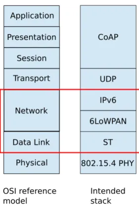
2.3 6LoWPAN
6LoWPAN is a standardized adaption layer to enable the transmission of IPv6 packets over IEEE 802.15.4 networks [6]. In the OSI reference model [23] it resides between the network and link layer (figure 3.2). This additional layer is needed to bridge the gap between the IPv6 protocol which requires a mimimum supported MTU of 1280 bytes while low-power wireless link layer protocols only support smaller message sizes, for example 127 bytes for IEEE 802.15.4 [14]. The main functionalities provided by 6LoWPAN are:
• Fragmentation of IPv6 packets into smaller link layer frames. A small fragmentation header containing a tag ID and packet offset is added to each fragment which allows reassembly into an IPv6 packet.
• Compression of the IPv6 header and potentially also upper layer head- ers. This is achieved by assigning default values to the header fields. Only header fields with non-default values are included in the 6LoWPAN frag- ment eliding the others.
2.4 Related Work
It has been argued that employing application layer gateways which act application-specific to connect the IoT is not a suitable approach to connect the envisioned billions of IoT devices because whenever a new device featuring a new application is added to the IoT network, the gateway device and potentially also the user application would have to be adapted. Instead a standardized approach to connect these devices independent of their application is needed, similar to how for traditional web services a single webbrower can connect to any website [24]. Applying the TCP/IP architecture to the IoT provides some challenges which have been studied before [1].
Currently IPv6 connectivity between traditional internet-capable devices and IoT devices can be achieved in two ways:
• Using routing protocols inside the constrained wireless multi-hop network.
Current industry standards mostly rely on the RPL protocol [5]. Examples for such standards are ZigBee IP [25] and OpenWSN [26].
• By restricting the topology to a star topology where every constrained node is just a single hop away from the edge router, no routing protocol is needed. Such a stack that uses IPv6 over Bluetooth Low Energy (BLE) is BLEach [27].
However these two approaches do not provide a network stack supporting a constrained wireless multi-hop network which supports node mobility. To achieve this, network stacks using synchronous transmissions protocols on the link layer and omiting the RPL protocol were proposed [13][28]. However these papers only established IPv6 connectivity within the constrained network and the concept of an edge router was presented but not implemented.
Chapter 3
Design
In this chapter the design of the proof-of-concept is presented. The goal of this design is to establish an end-to-end IP connectivity between a user and a constrained device. Therefore compatible network stacks and IP addresses are needed. The constrained network and the public internet are connected through an edge router. A directory server serves as rendez-vous point for user and constrained node. Metadata should then be exchanged to enable a meaningful interaction.
This chapter first explains why an IP gateway is not suitable. The following sections explain the network architecture and the procedure to enable the exchange of information between a user and constrained node.
3.1 Extending IP to the Edge
For successful communication between a user and a constrained node, they have to be able to address each other and the internet has to be able to route those addresses. The IP protocol is the standard which allows this. A solution for en- abling communication between traditional devices which rely on the IP protocol and a constrained node in a WSN is to not use the IP header inside the WSN.
This could save message overhead and complexity for the constrained node. The edge router could remove the IP layer and map the IP addresses to short link layer addresses (figure 3.1). ICMPv6 packets like ping could be translated and interpreted on the application layer.
However this approach has drawbacks: Without the IP header the constrained node cannot address an arbitrary host without a predefined mapping of a short link layer address to an IP address on the edge router. Therefore the constrained node could only respond to requests and would not be fully IP capable. It would not be able to contact an arbitrary directory server as described in 3.3.1 without preconfiguration on the edge router, making plug and play functionality impos- sible. Also the available address space would be much smaller which can be a
10
Figure 3.1: A gateway can connect two networks with incompatible network stacks performing translation of messages
problem for Machine-to-Machine (M2M) communication with a lot of connected devices.
Therefore an IP layer gateway as described above is not desirable. Instead the IP connection should be extended to the constrained node including all header information. However the header information can be compressed using lossless techniques as defined by the 6LoWPAN [6] specification.
3.2 Network Architecture
3.2.1 Network Stack
The network stack has to enable end-to-end communication between a user and constrained device. To achieve the compatability of the constrained network with the public internet and modularity which allows to improve certain functionalities independent of each other, a layered network stack is used.
The OSI model [23] is a conceptual model of a layered network architecture.
Comparing the OSI model to the network stack used in this thesis (figure 3.2) assigns the following protocols to each layer:
• Physical: 802.15.4 physical [14] layer is used, an established low-power wireless protocol. Its task is to physically modulate and demodulate the transmitted data over one hop.
• Link: A synchronous transmissions protocol together with parts of the IEEE 802.15.4 MAC [14] is used on the link layer. Its task is to deliver
3. Design 12
Figure 3.2: OSI reference model compared to the stack used for this thesis data over one link by enforcing “Medium Access Control” (MAC) rules in the form of a schedule. Important to note is that the synchronous transmissions protocol abstracts the entire constrained subnet as a single link and is therefore capable of delivering messages over multiple hops.
However there is no guarantee for successful reception, it is only a “best effort” service. More details about synchronous transmissions are explained in 2.1.
• Network: Two different protocols are used on the network layer:
– IPv6, together with routing protocols running on the network routers, provides a “best effort” service of delivering messages between two endpoints with potentially multiple links between them.
– 6LoWPAN [6] serves as an adaption layer between IPv6 and the syn- chronous transmission protocol by providing fragmentation and re- assembly of IPv6 packets which is necessary due to different MTU’s:
IPv6 requires a minimum MTU of 1280 byte while IEEE 802.15.4 [14], the physical layer that the synchronous transmission protocol relies on, only supports a MTU of 127 byte. 6LoWPAN also provides compression of IPv6 headers and potentially also upper layer headers.
• Transport: UDP is used as the transport layer protocol. It has a small
overhead and provides multiplexing between different applications on the same host by specifying source and destination ports.
• Session, Presentation, Application: All those layers are covered by the CoAP protocol [16] which is essentially a “lightweight HTTP” protocol de- signed for exchanging data between application endpoints in constrained environments. It has a compact header size and can provide reliable mes- sage delivery using a timeout and retransmission mechanism. It allows the application to GET, PUT, POST, DELETE or OBSERVE resources which are accesses using a “Uniform Resource Identifier” (URI) [29]. In the context of low-power applications it is desirable to keep the namespace flat and use short, not necessarily human-readable, resource names to keep messages as short as possible. For more details about CoAP see 2.2.
A few protocols deserve discussion as to why they are used:
• IPv6 vs IPv4: The main reasons for choosing IPv6 over IPv4 are:
– IPv4 is outdated by the IPv6 specification and should not be used in new deployments
– IPv4 addresses have a size of 32 bit which equals 232 ≈ 4.3 billion ad- dresses which is not even one address per person living on the planet.
On the other hand IPv6 uses addresses with a size of 128 bits which allows 2128 ≈3.4×1038 addresses.
• UDP vs TCP: TCP is the standard transport layer protocol for tradi- tional webservices. However UDP is the better option for the IoT scenario of this document, due to the following reasons [30]:
– The header size of TCP is at least 12 byte greater than the UDP header. This could be mitigated by expanding the 6LoWPAN capa- bilities to compress the TCP header.
– Lack of flexibility: TCP always provides reliable delivery with re- transmissions, while UDP does not provide this service but it can be guaranteed by CoAP on the application layer, depending on the appli- cation requirements. Hence, it is better suited for different scenarios where the system designer should have the flexibility to choose.
– A single request suffers from higher latency with TCP due to the three-way handshake when the connection is established, while UDP does not need to establish a connection first. This is especially im- portant for the application scenario considered in this document and described in 1.2 where it is stated that messages are only infrequently exchanged.
3. Design 14 – TCP requires both endpoints to keep state about the connection which is a concern for constrained devices. It can be argued that when using UDP and CoAP with reliability enabled, the state observing timeouts and performing retransmissions is moved to the application layer. However only the CoAP client (the host which issues a request) needs to keep this state and as described in the application scenario in 1.2 the constrained nodes primarily function as CoAP servers and not clients.
– TCP is a unicast protocol and does not support multicast in contrast to UDP. One property of synchronous transmissions is that by flooding all messages in the entire constrained subnet, it provides an efficient broadcast mechanism with the same cost as a unicast. This advantage can not be exploited when using TCP.
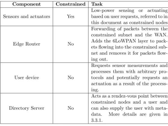
3.2.2 Network Components
Network components can be devided into constrained and non-constrained devices with an overview in table 3.1. The edge router, directory server and user device can be located anywhere on the planet as long as they are connected to the public internet (figure 3.3). Those three non-constrained components are logically separated but can be physically located on the same device. For the proof-of-concept presented in this document the directory server and user device are mapped to the same physical device.
Each constrained node has a unique identifier which is also known to the user. This identifier should be statically assigned during manufacturing and reported to the users that are authorized to perform interactions with the device.
The IPv6 address is not suitable as such an identifier because the first part of the address is the network prefix which changes depending on the deployment location and is therefore not static. The unique identifier chosen in this document has a size of 64 bits and follows the EUI64 format [31].
Component Constrained Task Sensors and actuators Yes
Low-power sensing or actuating based on user requests, referred to in this document as constrained nodes
Edge Router No
Forwarding of packets between the constrained subnet and the WAN.
Adds the 6LoWPAN layer to pack- ets flowing into the constrained sub- net and removes it for packets flow- ing out.
User device No
Requests sensor measurements and processes them with arbitrary pro- tocols and potentially requests an actuation as a result of the process- ing.
Directory Server No
Acts as a rendez-vous point between constrained nodes and a user and can also supply the user with meta- data. More details are given in 3.3.1.
Table 3.1: Network components are divided in constrained and non-constrained devices
Figure 3.3: Topology of the network components
3. Design 16
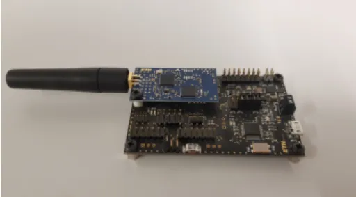
Figure 3.4: Dual Processor Platform with APP and COM board
Figure 3.5: Dual Processor Platform with Baseboard and COM board 3.2.3 Modular Hardware
One of the challenges mentioned in 1.4 are the strict timining requirements of the synchronous transmission protocol which must not be disturbed by the upper layer protocols or application software in order to enable successful communica- tion. This is hard to guarantee if all the software components are executed on a single processing unit. A solution is the “Dual Processor Platform” (DPP) [32]
developed at ETH Zurich. It allows isolating different task sets onto dedicated hardware. The DPP consists of two physically separated boards each featuring its own low-power microcontroller, the APP and COM board. The COM board includes a wireless radio and is typically used for wireless communication while the APP board is used for application tasks like sensing or actuating. The boards are interconnected using BOLT [33], a stateful processor interconnect that al- lows decoupling of power, clock and time domains of the two processing elements by allowing asynchronous message passing with formally verified bounds on the execution time.
Further benefits of this architecture are:
• Modularity: Each component can be exchanged indepent of the other one.
• Parallel development: Software for the components can be developed independently.
• Independent power management: Each component can take indepen- dent decisions on when to utilize low-power modes.
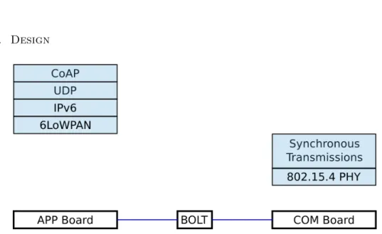
In this project, the COM board does not handle the entire network stack but only the time critical part which is the synchronous transmission protocol (figure 3.6). This allows the COM board to participate in the synchronous transmissions and asynchronously read 6LoWPAN fragments from BOLT to transmit and write received fragments to BOLT.
For the edge router a similar architecture is used as for the constrained nodes: It
Figure 3.6: Physical and link layer protocols mapped to COM board; network, transport and application layer mapped to app board
features the same COM board but the APP board is replaced by a more powerful board which also includes an Ethernet interface to provide the connectivity to the WAN.
3.3 Information Exchange
Having compatible network stacks between user devices and constrained nodes is only the first step to enable the exchange of information. The next steps necessary are establishing connectivity between the devices and then adding meaning to the exchanged data to extract information and enable interactions.
Those steps are described in the following sections.
3.3.1 Establishing Connectivity
For an IoT solution to be practical in real-world scenarios, the amount of config- uration needed by humans has to be minimized and plug and play connectivity is desirable [34]. With the prerequisite of compatible network stacks fulfilled, the next steps for establishing connectivity between user device and constrained nodes are:
• Local registration(figure 3.7): To be able to send messages within the synchronous transmissions protocol a node needs an ID which is unique within its subnet. The EUI64 [31] identifier of each node already satisfies this condition but is not suitable because of its 64 bit size. Instead an ID as short as possible to minimize the header size and therefore saving energy but as long as needed to support the number of nodes within a subnet should be used. A local ID of 16 bit size allows for 216 = 65536 different
3. Design 18
Figure 3.7: Local registration assigns nodes a local link layer ID which enables them to communicate within the constrained subnet
Figure 3.8: Global registration assigns an IPv6 address to each node and reports this address to a directory server
Figure 3.9: User can query directory server to learn node IPv6 address nodes per subnet which is unlikely to be exceeded. The assignment of this local ID is performed by the edge router which receives a request from the constrained node including its EUI64 identifier. The edge router maps it to a local ID and sends it back to the node. However because the node does not yet have a local ID it can not send a regular message, instead an extra contention slot designated for local registration messages needs to be included in the schedule of the synchronous transmissions protocol.
• Global registration (figure 3.8): To be able to send and receive IPv6 packets the nodes need a globally unique, routable IPv6 address. An IPv6 prefix is delegated to the edge router by its internet service provider which the edge router then advertises periodically within its subnet. Ideally this prefix has a size of at most 64 bit which allows the node to directly derive its 128 bit IPv6 address by performing stateless address autoconfiguration [35], essentially concatenating the prefix and the EUI64 with one bit in- verted which results in a globally unique and routable address. However if the subnet prefix has a size of N > 64 bit, the EUI64 must be hashed to an identifier of size 128−N bit and its uniqueness within the subnet needs to be verified by performing a “Duplicate Address Detection” (DAD). If the derived identifier is unique within the subnet, then the IPv6 address resulting from concatenating the prefix and the identifier is globally unique and routable because the prefix is globally unique. Finally after having as- signed itself a public IPv6 address the node needs to advertise this address to a directory server for users to be able to learn the nodes address. This
3. Design 20
Figure 3.10: Thing Description describes interfaces and static metadata directory server is located somewhere in the cloud and hosts a database with key-value pairs of EUI64-IPv6 address and allows nodes to add entries to the database and users to read the database.
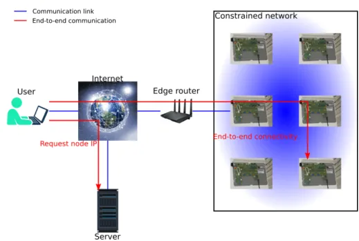
• Connect (figure 3.9): After the node has added its IPv6 address to the directory server database, the user can query the directory server to learn the address of the node and is then able to exchange messages with it.
The assumption made for this scheme is that every node has a unique identifier in the EUI64 [31] format which is assigned during manufacturing and the user knowns the identifier of the node with which they want to connect.
3.3.2 Enable Interaction
Meaningful application layer interaction between a user and a constrained node is only possible if they can make sense of each others messages. Us- ing a “Thing Description” (TD) [36] provides a standardized way of describ- ing a devices interface and its metadata. An excerpt of such a TD for a constrained node which features a temperature sensor could look like this:
Figure 3.11: Additional location-dependent metadata is needed to add meaning to data
1 " p r o p e r t i e s ": {
2 " t e m p e r a t u r e ": {
3 " t i t l e ": " T e m p e r a t u r e "
4 " t y p e ": " int " ,
5 " m i n i m u m ": -40 ,
6 " m a x i m u m ": 125 ,
7 " u n i t ": " om : d e g r e e _ C e l s i u s " ,
8 " f o r m s ": [{
9 " h r e f ": " c o a p s :// m y n o d e . e x a m p l e . com / t e m p " ,
10 " cov : m e t h o d N a m e " : " GET "
11 }]
12 }
13 }
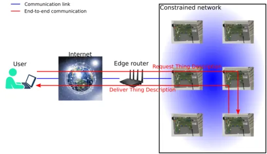
In this example we can see that a temperature can be requested from the device by performing a CoAP GET request. The returned value is an integer in the range from -40 to 125 and its unit is degree Celsius. There are two possibilities how this TD could be delivered to the user:
• It can be exposed as a separate CoAP resource by the constrained node which can then be requested by the user (figure 3.10).
• It can be delivered to the directory server upon registration of the con- strained node and the user can request if from there to take load off the constrained node. However this creates a challenge of potential inconsis-
3. Design 22 tency if the interface of the constrained node changes due to a software update.
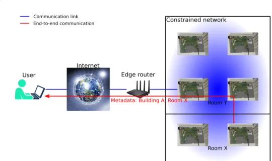
But to interprete and act upon received data, typically more metadata is needed which depends on the location where the constrained node is placed (figure 3.11). This metadata is usually not known at the time of manufacturing and therefore can not be included in the TD delivered by the constrained node.
The person that installs the constrained nodes, for example a handyman, has to add the location-dependent metadata to a database which is accessible to the user. This database could be located on the directory server or the edge router, but the details of this procedure are out of scope.
Implementation
This chapter presents the implementation of each of the network components:
Constrained nodes, edge router, directory server and user device. The source code will be made publicly accessible and instructions on how to access it are given in chapter 7. The hardware of the constrained nodes and the edge router was developed at ETH Zurich [37].
4.1 Constrained Node
The constrained nodes are realized on the DPP [32] hardware consisting of an APP and a COM board which are interconnected through BOLT [33] (figure 3.4).
4.1.1 APP Board
The APP board is responsible for part of the network stack, the 6LoWPAN layer and above (figure 3.6), as well as the application. The main implementation task is to port Contiki-NG [15] to the MSP432 microcontroller. Contiki-NG is chosen because it was developed specifically for low-power communication on embedded devices and supports the IPV6, 6LoWPAN, UDP and CoAP standards which are all the network protocols needed on the APP board. Porting included the implementation of timers, clock and interrupts and drivers for UART, GPIO, SPI and high level interfaces for sensors and LEDs.
Because the link and physical layer of the network stack are not mapped to the APP boards, those layers are replaced with custom implementations in the Contiki-NG stack:
• Radio layer: The essential part of the radio layer is the BOLT driver which is used to write data to BOLT if a transmission is requested by the upper layers, and forwards data received from BOLT to the upper layers.
23
4. Implementation 24 Reception of data can be done either in poll or interrupt mode and this mode can be chosen by the upper layers.
• MAC layer: A MAC called simplemac is implemented which does not enforce any MAC rules since that is handled by the synchronous trans- missions on the COM board. Simplemac adds a link layer address and sequence number to filter out packets not addressed for the constrained node and detect duplicate link layer frames. If the radio layer fails to write to BOLT because the queue is full, simplemac reports a collision during transmission back to the upper layer. This indicates that a transmission should be tried again at a later time when the queue is not full anymore.
As an example application a sensor and actuator are implemented:
• Temperature sensor: temperature values can be read from a SHT30 sensor [38] and are exposed as a CoAP resource which can be accessed by a GET request. Additionally a client can also OBSERVE the temperature value. This means a client will be notified when the temperature rises above a certain threshold value.
• Cooling actuator: Another CoAP resource exposed is a cooling actuator.
A client can request the cooling to be turned on or off by issuing PUT requests. The actuator is mapped to a LED present on the APP board:
The LED is on when the node received a request to turn the cooling on, and vice versa.
It was not possible to obtain public IP addresses for the constrained nodes.
Therefore a local, not publicly routable network prefix is assigned to the nodes statically during compile time and the node forms its IPv6 address using stateless address autoconfiguration [35] but no DAD is performed. This creates a challenge for the user connecting to the constrained node as its IPv6 address is not globally routable. It is overcome by the use of an IP tunnel which is explained in 4.5.
The limited available RAM on the APP board also proved to be a challenge.
A sufficient amount of buffers on all layers of the network stack could not be provided. Therefore the required minimum MTU of 1280 byte for the IPv6 standard can not be fulfilled. The node can handle IPv6 packets of a size up to
≈800 byte.
4.1.2 COM Board
The code running on the COM board is based on an example provided by Baloo [39]. Baloo [39] is a design framework that allows easy development of a custom synchronous transmissions protocol. A synchronous transmissions protocol with a round-based static schedule is used (figure 4.1). The interval between consec- utive rounds is 1 s. The list of nodes is statically defined and each node gets a
Figure 4.1: The synchronous transmission protocol used is round based with round-robin assignment of communication slots
slot assigned during which it is allowed to transmit its data. The COM board reads 6LoWPAN fragments from the BOLT interface before its assigned data slot starts, during the time period where no communication happens. If data was received from BOLT then the node transmits it in its communication slot.
After each communication slot the COM board writes the received 6LoWPAN fragments to the BOLT interface. No filtering based on destination address is performed since the COM board is not aware of the upper layer protocols and does not reassemble the 6LoWPAN fragments into IPv6 packets. This allows the COM board to operate independent of the protocols used on the APP board and simply provides the service of flooding a 6LoWPAN fragment in the entire subnet. Nodes which are not intended recipients of an IPv6 packet can then drop it on the APP board.
The implementation is lacking the local registration process described in 3.3.1.
Instead fixed IDs and a static schedule are assigned during compile time.
4.1.3 Bolt
The software running on the BOLT microcontroller is a binary provided by a publicly accessible repository [40].
4.2 Edge Router
The edge router device is also implemented on a dual processor platform [37].
However in contrast to the constrained nodes the APP board is exchanged for a more powerful Baseboard which is not considered a constrained device and includes an Ethernet interface (figure 3.5). The edge router also features a COM board which is connected to the Baseboard through the BOLT interconnect.
The implementation of the COM board and BOLT are identical as presented in 4.1. The COM board placed on the edge router is typically configured to be the host node of the synchronous transmissions protocol, however this is not a requirement.
4. Implementation 26 4.2.1 Baseboard
The baseboard runs a Linux-based operating system (OS) and features a Colibri iMX7 [41] processing unit. The operation for packets flowing in both direction is as follows:
• Traffic from constrained node to user: 6LoWPAN fragments are re- ceived from the BOLT interface. The 6LoWPAN layer handles the reassem- bly of 6LoWPAN fragments into header-compressed IPv6 packets and then decompresses the IPv6 header. Because of the use of local IPv6 addresses on the constrained nodes, the IPv6 packet is wrapped with another IP header as described in 4.5. The resulting packet is then sent to the user through the Ethernet interface with is implemented by the Linux OS.
• Traffic from user to constrained node: Packets arrive at the baseboard through the Ethernet interface. The Ethernet and IP tunnel headers are removed and the IPv6 packet extracted. The 6LoWPAN layer is added to the packet and then forwarded to the BOLT interface for transmission into the WSN.
The BOLT interface and packet manipulation was implemented in Python relying on the Scapy [42] packet manipulation library. Due to a software bug in this library the edge router is not able to perform 6LoWPAN fragmentation and header compression correctly. Therefore only unfragmented packets can be successfully delivered to the constrained nodes. It is however able to reassemble 6LoWPAN fragments and decompress the IPv6 header. The issue has been addressed on the Gitter forum [43].
4.3 Directory Server
The directory server is implemented in Python and hosts a simple database containing key:value pairs, where the key is the EUI64 identifier of a constrained node and the value is the corresponding IPv6 address. The database is accessible through a CoAP interface. Constrained nodes add their EUI64 and IPv6 address to the database using PUT or POST requests and users can read the database using GET requests as described in 3.3.1. The CoAP interface is implemented using the CoAPthon [44] library.
The hardware used is a Lenovo ThinkPad T450s [45] with an Ubuntu 18.04 OS and connected to the internet through Ethernet. The laptop receives a public, globally routable IPv4 and IPv6 address from the network.
Figure 4.2: IP tunnel from user to edge router: user adds an additional IP layer addressed to the edge router which is removed before forwarding
4.4 User
The user can use the Linux command line interface (CLI) to issue ICMPv6 ping requests and simple CoAP requests using the CoAPthon [44] example client. A more complex CoAP-based interaction between user and constrained node as presented in 5.4 is implemented in Python using the CoAPthon library.
The hardware used is a Lenovo ThinkPad T450s [45] with an Ubuntu 18.04 OS and connected to the internet through Ethernet. The laptop receives a public, globally routable IPv4 and IPv6 address from the network.
4.5 IP Tunnel
If globally routable IPv6 addresses are not available for the constrained nodes as it is in this work, a direct IPv6 connection between user and constrained node can still be achieved by using an IP tunnel. When the user sends an IPv6 packet to a constrained node, an additional IP layer is added. This additional IP layer has the edge router address as destination which is a globally routable address.
The tunnel can use either IPv4 or IPv6 but for practical reasons an IPv6-in-IPv4 tunnel is used in this work. The edge router then removes this additional IP layer before forwarding the packet into the WSN (figure 4.2).
The use of an IP tunnel does not affect the functionality and the implementa- tion can easily be adapted in case globally routable addresses are available. The mapping of a node ID to global edge router IP to which a tunnel should be es- tablished could also be stored on the directory server and could work completely dynamic as well. However in this work the tunnel was configured statically.
Chapter 5
Evaluation
Several experiments are conducted to evaluate the performance and functionality of the implemented solution. The setup and results of those experiments are presented in this chapter.
5.1 Experiment Setup
An overview of the conducted experiments is presented in table 5.1. The goal of the experiments is to demonstrate the functionality of CoAP, ping and frag- mentation. Also the impact of node mobility and scaling shall be analyzed us- ing the performance parameters of success rate and delay. The functionality of connection establishment and metadata exchange are demonstrated in 5.4. The following subsections explain the topology and traffic pattern of the experiments.
5.1.1 Topology
The experiments 1, 2 and 3 (figures 5.1,5.2,5.3) are performed with the use of FlockLab [46] nodes which only serve as forwarders in the synchronous trans- missions protocol to form a multi-hop network. For those experiments the user device and edge router are both directly connected via Ethernet.
The experiments 4, 5 and 6 use a topology of only a single constrained node which is placed in communication range of the edge router. For experiment 4, user device and edge router are both connected to the ETH network. Experiment 6 uses again a direct Ethernet connection between user device and edge router.
For experiment 5, both connection types are used.
5.1.2 Traffic
CoAP requests in the experiments use a timeout of 15 s after which the sample is considered not successful. CoAP requests use a maximum of two retransmissions
28
Exp. Description Goal
1
User issues a sequence of CoAP re- quests on the temperature of a con- strained node which is placed in a static location several hops away from the edge router. The user de- vice has a direct Ethernet connec- tion to the edge router.
CoAP func- tionality, reference measurement
2
User issues a sequence of CoAP re- quests on the temperature of a con- strained node which is moving in- side the network. The user device has a direct Ethernet connection to the edge router.
Comparison to static case
3
User issues a sequence of CoAP re- quests on the temperature of a con- strained node which is placed in a static location several hops away from the edge router. Four nodes are removed from the WSN com- pared to experiment 1. The user device has a direct Ethernet connec- tion to the edge router.
Comparison to full topology
4
User issues a sequence of CoAP requests on the temperature of a constrained node which is placed in single-hop distance of the edge router. User and edge router are connected to the internet
Compatability with public internet
5
User issues a sequence of ICMPv6 ping requests to a constrained node which is placed in single-hop dis- tance of the edge router. Both a direct Ethernet connection be- tween user and edge and connection through the internet are tested.
Ping function- ality
6
User issues a sequence of CoAP requests discovering the resources of a constrained node (response requires fragmentation) which is placed in single-hop distance of the edge router. The user device has a direct Ethernet connection to the edge router.
Fragmentation functionality
Table 5.1: 6 experiments are performed to evaluate performance and functional- ity
5. Evaluation 30
Figure 5.1: Static multi-hop topology
Figure 5.2: Mobile multi-hop topology. The mobile node moves with a velocity of approximately 1-2 m/s
Figure 5.3: Static multi-hop topology with some nodes removed
Figure 5.4: Interval between each request is randomly generated
5. Evaluation 32 Exp. 1 Try 3 Tries
Static 97.2% 100%
Mobile 83.3% 98.6%
Static scale-down 100% 100%
Table 5.2: Success rate of CoAP requests for experiments 1 (static), 2 (mobile) and 3 (static scale-down) for a single try and with retransmissions
after the inital request is sent. Ping requests dont use retransmissions. To offer independence of the samples, consecutive requests shall only be sent after the network is silent again. A minimum of 20 s between requests delivers sufficient confidence to guarantee this.
For a single test run a sequence of 9 requests is used. The interval between two consecutive requests is randomly generated with uniform distribution in the interval [20 s, 30 s] with a resolution of 0.1 s (figure 5.4). 8 such sequences Y1, ..., Y8 are generated and stored.
Experiments 1, 2 and 3 are repeated 8 times, one run for each random sequence generated. This provides 72 samples of success and delay for those experiments.
The experiments 4, 5 and 6 are only performed once using the random sequence Y1 which provides 9 samples of success and delay for each experiment.
5.2 Experiment Results
The hypothesis is that by using synchronous transmissions, the success rate and delay is not significantly impacted by node mobility. However the success rate in the mobile experiment is worse than for the static case (table 5.2). The ex- planation for this observation is that in the mobile experiment the node changes from locations of good connectivity to locations with bad connectivity. There- fore packets losses occur more often than for the static node placed in a location with good connectivity. The topology with four nodes removed performed best with a success rate of 100% even without retransmissions. This illustrates that for synchronous transmissions, a higher node density does not necessarily lead to increased reliability as was also shown by others [47].
If the success rate after retransmissions is considered, the mobile scenario could also almost achieve full reliability on application layer with only 1 request not be- ing successful. For RPL based communication, a lot more retransmissions would be needed to reach a similar success rate for a mobile scenario if the success rate of a single message is below 20% (figure 5.10).
From the distribution of the response time of successful requests the retrans- missions are clearly visible (figures 5.5,5.6,5.7): the majority of the requests is centered around 2 s which are the requests that succeeded in the first try. Re- transmissions are visible around 4 s and 8 s.
Figure 5.5: Response time distribution experiment 1
Figure 5.6: Response time distribution experiment 2
5. Evaluation 34
Figure 5.7: Response time distribution experiment 3
To compare the response times of the static and mobile scenario, only the re- sponse times from requests which succeeded in the first try are considered. This provides a fair comparison as requests issued when the mobile node was in a lo- cation of bad connectivity are not considered. The empirical median and average response times from the experiments are calculated as well as upper bounds for the 50th,75th and 90th percentile. The calculations of these upper bounds are following the guidelines of the TriScale [48] framework and use a confidence of at least 95%. The values of theses upper bounds as well as the empirical median and average values show a difference of less then 2% and the mobile scenario does not have strictly worse metrics (table 5.3 and figure 5.8). We can therefore conclude with high confidence that the response time distribution of a single successful CoAP request is identical in the static and mobile scenario.
The results of experiments 4, 5 and 6 (table 5.4) demonstrate that the system is also capable to handle ping requests and packet fragmentation. Communication is also possible if the edge router and user device are connected to the internet instead of a direct Ethernet connection between them. Fragmentation takes sig- nificantly longer because only one fragment can be transmitted per round of the synchronous transmissions protocol.
The delay measurement has to be viewed with care as it highly depends on the synchronous transmissions protocol used and the configured round time which is 1 s in the experiments.
Median[s] Average [s]
Static 1.983 2.021
Mobile 2.013 2.03
Difference 1.51 0.45
Table 5.3: Response time empirical values of requests which succeeded in the first transmission
Figure 5.8: Upper bounds for the 50th, 75th and 90th percentiles of the response time of requests which succeeded in the first transmission
Experiment Success Rate Median Response Time Upper Bound[s]
CoAP request, internet
connection (Exp. 4) 100% 2.243
Ping, direct connection
(Exp. 5) 100% 2.321
Ping, internet connec-
tion (Exp. 5) 100% 2.397
CoAP fragmentation (3 fragments), direct con- nection (Exp. 6)
100% 4.385
Table 5.4: Success rate and response times of experiments 4, 5 and 6
5. Evaluation 36
5.3 Mobility Comparison to Industry Standards
Current industry standards like ZigBee IP [25] and OpenWSN [26] rely on the RPL protocol. A comparison between the success rate from this work without retransmissions (table 5.2) and simulations of RPL performance (figures 5.9 and 5.10) under different mobility models [7] indicate a much improved mobility support for the stack presented in this document. The reliability of the network stack presented here drops to 83.3% whereas for RPL it drops to below 20% for most mobility models. It is important to keep in mind that the results from this work measured the success rate of a request/response pair where a packet can be lost in both directions, whereas the RPL evaluation only considers the success rate for packet delivery in one direction.
Figure 5.9: Packet Delivery Ratio with RPL protocol in a static scenario [7]
Figure 5.11: Remote monitoring and control of fridge temperature
Figure 5.10: Packet Delivery Ratio with RPL protocol in different mobility mod- els [7]
5.4 Demonstration
The functionality of the network stack and the network devices is demonstrated using an example scenario. Two constrained nodes A and B are used together with the edge router and a laptopt which serves as the user device as well as the directory server (figure 5.12). Nodes A and B register their IP address at the directory server using CoAP POST requests as described in 3.3.1. The user can then extract the list of IP addresses using a CoAP GET request. The user can then test the node connectivities using ICMPv6 ping requests. The available CoAP resources can be discovered and metadata can be exchanged by requesting the TD. It can be seen that node A offers a temperature sensor and node B offers
5. Evaluation 38
Figure 5.12: The demonstration topology a cooling actuator which shall be used for the example application.
The IP addresses of the two nodes serve as inputs for the example user applica- tion. A CoAP OBSERVE request on the temperature of node A is then issued.
This causes the user to be notified when the temperature on node A rises above 30 degree Ceclsius. When this happens, the application sends a CoAP POST request to node B to actuate the cooling, which is simulated by the activation of an LED on node B (figure 5.13). This example scenario could reflect the remote monitoring and control of an appartment cooling (figure 5.11).
Figure 5.13: A blow-dryer triggers the temperature rise
Chapter 6
Conclusion
The need for an IoT networking stack which can handle node mobility and en- able webservice-like interactions in a standardized, application-independent way is motivated in chapter 1. A background about the key technologies synchronous transmissions, 6LoWPAN and CoAP together with related work is presented in chapter 2. Using these technologies, a design for a proof-of-concept is constructed in chapter 3. The design lays out the needed network components and their pro- tocol stacks as well as the steps to enable application layer interactions between a user and a constrained node. The implementation of each network component is elaborated in chapter 4. Chapter 5 evaluates the system performance in terms of success rate and delay of CoAP and ICMPv6 ping requests. A comparison to RPL based communication shows that the network stack proposed in this thesis has a significantly lower packet loss rate in the presence of node mobility. By using a maximum of two retransmissions on the application layer a reliability of 98.6% in a mobile scenario and 100% in a static scenario is achieved.
The following subsections analyze wheter the thesis goals are met and what work still has to be done to transform this proof-of-concept to an IoT networking stan- dard.
6.1 Findings
The proof-of-concept presented in this thesis demonstrates that IP-based application layer interactions between traditional internet-capable devices and constrained nodes is feasible. By using synchronous transmissions on the link layer, messages can be delivered with high reliability in scenarios with mobile nodes, significantly higher than communication based on RPL which is used in current industry standards. The use of the CoAP protocol provides a webservice-like interface. This makes it convenient for programmers which are used to the HTTP protocol to develop IoT applications. However it needs to be considered that response times will typically be much bigger than what programmers are used to from traditional webservices. For the implementation
40
used in this thesis the response time for a CoAP request is at least 1.5 s compared to a few tens of miliseconds for traditional HTTP webservices. Therefore bigger timeout values need to be used for IoT communication to not overwhelm the WSN, especially since the transport layer protocol used in this thesis is UDP which does not offer flow and congestion control.
The evaluation presented in this thesis shows that 100% reliability can be achieved on the application layer for static scenarios for both CoAP and ping requests. This proves that the system is functional. Because the edge router implementation does not operate above the IP layer, we argue that any other transport or application layer protocol can be successfully delivered without the need to change the edge router implementation. This proves that the edge router is an application-independent gateway. However the system is not fully IPv6 capable in its current state due to implementation limitations: The edge router can not fragment IPv6 packets into smaller link layer frames but it can reassemble them. This is due to an implementation bug in the underlying library. The constrained nodes can only send and receive IPv6 packets up to a size of ≈800 byte due to limited memory available for buffers. Therefore the MTU of 1280 byte for the IPv6 standard is not supported. These limitations come only from implementation details and can be solved by code improvements.
The proof-of-concept also demonstrates how application layer interactions between a user and constrained node are enabled with minimal manual configu- ration. This is achieved by adherence to standards, shared knowledge about the EUI64 identifier of the constrained node and the address of the directory server and the exchange of metadata using Thing Descriptions.
6.2 Future Work
To enable the transformation of the network stack presented in this thesis to an IoT networking standard, the following future work is needed:
• Code improvements to support the MTU of 1280 byte required by the IPv6 specification and to optimize the system performance. Also the registration process to automate IP and link layer address assignment needs to be implemented for plug-and-play functionality.
• Synchronous transmissions need thorough performance evaluation in differ- ent scenarios. Ideally, a single general-purpose protocol is developed which is adaptable and performs well in any scenario.
6. Conclusion 42
• Support of redundant edge routers to eliminate the ”Single Point of Failure”
which is currently present by using a single edge router. Synchronous Transmissions are suitable for this because messages are implicitly flooded in the entire network.
• Thorough benchmarking against routing-based standards to evaluate which approach performs better in different scenarios.
A further improvement could be the implementation of a CoAP interface on the edge router. This interface could allow a user access to a list of the constrained nodes present in the edge routers subnet which would enable the user to establish a connection if the directory server does not exist anymore.
The interface could also allow the user access to network statistics and changing parameters of the synchronous transmissions protocol.
The implementation of the edge router as a CoAP proxy between user and constrained node could also be beneficial. This proxy could handle retransmis- sions in case of packet losses. Retransmissions inside the WSN caused by a packet loss outside of the WSN could therefore be avoided.
Appendix
7.1 Online Resources
All source code developed in this thesis as well as detailed measurements of the experiments and the code used to produce the experiments will be made publicly accessible in a GitLab repository [49].
43
Bibliography
[1] Wentao Shang, Yingdi Yu, Ralph Droms, and Lixia Zhang. Chal- lenges in IoT Networking via TCP/IP Architecture. Technical re- port, ucla,cisco, 2016. URL https://pdfs.semanticscholar.org/e4ef/
f4b8cc9636783ab3054f2976d1975cdd3cba.pdf.
[2] Harvard Business Review. Internet of things: Science fiction or business fact? 2014. URL https://hbr.org/resources/pdfs/comm/verizon/
18980_HBR_Verizon_IoT_Nov_14.pdf.
[3] Manish Mahato. Internet of things (iot): Research, architectures and appli- cations. 2018.
[4] Oliver M Heckmann. The competitive Internet service provider: network architecture, interconnection, traffic engineering and network design. John Wiley & Sons, 2007.
[5] Tim Winter, Pascal Thubert, Anders Brandt, J Hui, Richard Kelsey, Philip Levis, Kris Pister, Rene Struik, JP Vasseur, R Alexander, et al. Rpl: Ipv6 routing protocol for low-power and lossy networks. rfc 6550. 2012. ISSN 2070-1721. URL https://tools.ietf.org/html/rfc6550.
[6] Gabriel Montenegro, Nandakishore Kushalnagar, Jonathan Hui, David Culler, et al. Rfc 4944: Transmission of ipv6 packets over ieee 802.15.4 networks. 2007. URL https://tools.ietf.org/html/rfc4944.
[7] Hanane Lamaazi, Nabil Benamar, and Antonio J Jara. Rpl-based networks in static and mobile environment: A performance assessment analysis.Jour- nal of King Saud University-Computer and Information Sciences, 30(3):
320–333, 2018.
[8] Federico Ferrari, Marco Zimmerling, Lothar Thiele, and Olga Saukh. Effi- cient network flooding and time synchronization with glossy. InProceedings of the 10th ACM/IEEE International Conference on Information Processing in Sensor Networks, pages 73–84. IEEE, 2011.
[9] Marco Zimmerling, Luca Mottola, and Silvia Santini. Synchronous trans- missions in low-power wireless: A survey of communication protocols and network services. arXiv preprint arXiv:2001.08557, 2020. URL https:
//arxiv.org/abs/2001.08557.
44
![Figure 2.1: Glossy floods a message in the entire network [8]](https://thumb-eu.123doks.com/thumbv2/1library_info/5355671.1683141/13.892.183.722.154.388/figure-glossy-floods-message-in-the-entire-network.webp)