Systematic Studies of Different Adhesives for Application in HEC for
ATLAS Detector
Project Report
Submitted on Internship Results
To
Max Planck Institute for Physics
Foehringer Ring 6 Munich – 80805
Germany By
Himani Arora
Graduate Student Advanced Functional Materials
Institute for Physics University of Augsburg Augsburg-86159, Germany
June 2013
ACKNOWLEDGEMENTS
I would like to express my heartfelt gratitude to Dr. Sven Menke and Dr. Olaf Reimann for providing me opportunity and platform to carry out this project.
I am grateful to Mr. Hermann Wenninger and his Fabrication team for their guidance and support throughout the course of this work.
Special thanks to Mr. Alexander Fischer and Mr. Armen Hambarzumjan for their help in managing various test equipment for the project.
Last, but not the least, my deepest gratitude to whole ATLAS team and members of Max Planck Institute for Physics, Munich for their constant encouragement and help.
PREFACE
Adhesive bonding technology today plays a significant role in a variety of industries, including the automotive, aerospace, maritime, construction, defence etc. Many components and structures, from microchips to ships and large aircrafts are made of materials arranged in layers through adhesive bonding.
In the field of electronics, they are vital in the assembly and packaging of electronic devices.
Adhesives used in assembling semiconductor die, both in single-chip packages and in multichip assemblies are called die-attach or chip-attach adhesives.[1]
Due to their low cost, ease of rework, and low-processing temperatures, polymer adhesives have replaced many traditional interconnect materials such as solder, eutectic alloys etc.[1]
At our institute, these adhesives are used every day in the bonding Semiconductor dies with Gold frames which will be used subsequently in Hadronic End-Cap Calorimeter for ATLAS detector (HEC-ATLAS) at CERN, Geneva. However, in past, bonded dies encountered various problems of:
Unreliable bonding between the substrates and adhesive.
Inconsistency of the adhesive layer.
Failure and breakage of adhesive parts.
While not much information was available for the origin of these problems, a basic understanding of adhesives and their properties is necessary in their selection and application to assure performance and to avoid subsequent reliability problems.
The purpose of this project was to study how thermal shocks and cryogenic conditions affect the bond line strength and adhesion properties of structural adhesives that are commonly used in HEC-ATLAS at CERN, Geneva.
This study explores bond line strength and adhesive properties with different curing time- temperature schedule followed by thermal shocks from -196 °C (Liquid nitrogen temperature) up to +270 °C (Soldering reflow temperature) using shear force test measurements and visual inspections.
Apart from this, effort was made to provide a basic understanding and defining guidelines for selecting and qualifying adhesives based on the conditions the adhesive is expected to meet.
SCOPE OF THIS INVESTIGATION
This investigation on filled epoxy resins as adhesives was undertaken to provide design information for liquid Argon cooled Hadronic End-Cap Calorimeter for ATLAS detector. Since the adhesive would be acted upon by thermal stresses and electrical reaction forces, the present project was undertaken to evaluate the mechanical strength of several adhesives subjected to the treatment corresponding to their use in the end application.
This report covers how variation in curing schedule of the adhesive and thermal shocks affects bond line strength and physical properties of adhesives.
Four of such adhesives were chosen based on their technical datasheets provided by their supplier. (For detailed explanation of technical datasheet, see “Overview of Technical Datasheet” in later section of this report).
The adhesives chosen were:
Epo-Tek H70E from Epoxy Technology.
Epo-Tek H20E from Epoxy Technology.
SurABond HS25 from SurA Chemicals GmbH.
Stycast 2850 FT with Catalyst 24LV from Emerson & Cumings, Inc.
The selection of these adhesives was based on an earlier search for an adhesive useful at cryogenic temperatures. When it was found that these adhesives exhibit desirable low temperature properties, the next step was the verification of the fact that properties of the bond are not seriously harmed by some of the treatment the completed assembly would receive during application.
Tests Performed:
Thermal shocks in the form of repeated LN2 cycles (with an interval of 10 minutes).
Variation in Curing time and temperature of the adhesive.
Continuous immersion in LN2 bath for 2 days and 8 days.
Heating the bonded samples to soldering temperatures.
Analysis of the results:
Die shear testing is a standard method for checking the ultimate strength of an adhesive.
Visual inspection under microscope at higher magnifications.
Apart from testing shear strength of the adhesive, the effect of Area of Contact on Bond Strength; Increase in the Thickness of the adhesive layer with Bonding Strengths; Effect on Bond Strength of the adhesive layer with respect to increase in number of LN2 cycles given was also studied.
This work provided a highly useful database for comparing adhesive performance over a wide range of temperatures, and has facilitated selection of the appropriate adhesive for the required application.
CONTENTS
List of Symbols and Abbreviations ... 1
Introduction ... 2
Adhesive Types and Classifications ... 2
Functions of an Adhesive ... 4
Requirements from an Adhesive for our Application ... 6
Experimental Procedure ... 7
Plan of Action ... 7
Preparation of Samples ... 7
General Description of Tests Performed ... 10
Analysis of Tests Performed ... 12
Failures, Fractures and Phenomena Occurring ... 14
Tests with H70E ... 21
Tests with H20E ... 30
Tests with HS25 ... 34
Tests with Stycast 2850 FT with Catalyst 24LV ... 38
Final Suggestions ... 41
Area of Contact versus Bond Strength ... 42
Thickness versus Bond Strength ... 43
Number of LN2 Cycles versus Bond Strength ... 44
General Precautions ... 45
Overview of Technical Datasheet ... 46
References ... 53
LIST OF SYMBOLS AND ABBREVIATIONS
μm Micrometre
Al2O3 Alumina
AOC Area of Contact
°C Degree Celsius
CTE Coefficient of Thermal Expansion
in
Inch
kgs Kilograms
lbs Pounds
LN2 Liquid Nitrogen
mm Millimetre
Pb Lead
ppm Parts per Million
psi Pounds per Square Inch
RT Room Temperature
Sn Tin
UV Ultraviolet
w/mK Watts per metre per Kelvin
SECTION 1 INTRODUCTION
1.1. Adhesive types and classifications:
Adhesives used in assembling electronic circuits may be classified based on their physical form, polymer type, molecular structure, formulation, curing method, function, or intended application.
1.1.1. Classification by form:
In terms of their physical forms, adhesives may be:
Liquids
Solids
Pastes
Liquids are used where excessive flow or spreading is not a consideration. However, in most electronics applications, adhesive flow needs to be monitored precisely during cure. For such applications, pastes are generally preferred. They are highly filled with mineral fillers and thixotropic compounds such as fine silica powder which produces semi-solid properties and thus controlled flow behaviour. They are easy to dispense by forcing them through a needle or by pressing them through a screen or stencil.[1]
Paste or liquid adhesives, in turn, may be:
One-part: Contains a polymer resin system that cures directly on exposure to moisture, oxygen, UV light, or elevated temperature.
Two-part adhesives: Consist of two separate resin portion - Part A and Part-B (hardener or catalyst portion). The two parts are packaged and stored in separate containers. When ready for use, the parts are weighed, mixed, deaerated, dispensed, and cured. [1]
For our experiments, the four adhesives used were all paste adhesive with two-part components.
1.1.2. Classification by polymer or chemical type:
Polymer types which are suitable for bonding electronics assemblies are epoxies, silicones, acrylics, polyurethanes, polyimides, and cyanate esters. Polyurethanes were used where flexibility and vibration damping of large components were required. Both cyanoacrylates and anaerobic adhesives provided very rapid curing in the absence of air, but poor resistance to elevated temperature-humidity environments.[1]
The four adhesives used in the experiments were all epoxy based adhesives.
Why Epoxides?
Epoxides have best combination of properties suitable for electronics packaging. They have high adhesive strength to almost all surfaces, thermal stability, dielectric properties, and retention of the properties under high thermo-mechanical stresses and elevated temperatures and humidity. Apart from excellent properties, ease of curing and processing, low cost, and ease of reworking makes them most widely used and most versatile of the polymer types. Though the choice of hardeners, catalysts, fillers, and other additives and by controlling the degree and method of curing, properties can be tailored.[1]
They are formed by polymerization of epoxy with a variety of curing agents, hardeners, or catalysts. “A hardener is a curing agent that reacts with a resin and becomes part of the polymer through cross-linking while a catalyst is also a curing agent that initiates polymerization of the resin, but does not become part of the final polymer structure”.[1]
1.1.3. Classification by curing method:
Curing means mostly polymerization which requiring a catalyst or hardener. Polymerization is initiated by some form of energy which can be provided in any form.
1. Heat-cured adhesives:
Heat curing by convection in ovens is the most widely used and simplest method for curing adhesives. Heat is applied until a temperature is reached at which polymerization occurs and continues at constant temperature until the polymerization is complete. Curing schedules comprising of suitable temperature conditions applied for a certain period of time are developed for each adhesive for which optimum properties are achieved. For each of their adhesives, suppliers provide several cure schedules that are considered equivalent relative to final properties.
Sometimes Snap-cured adhesives are also used that cure in less than 1 minute at temperatures of 160–170 °C, in order to reduce energy costs and increase mass production of consumer electronics.
Other popular methods of curing are:
2. Ultraviolet (UV)/visible-light-cured adhesives 3. Microwave curing
4. Moisture curing
Out of four adhesives chosen, two were heat cured while rest two were cured at Room Temperature (RT) first followed by post heat cure.
1.2. Functions of an Adhesive:
1.2.1. Mechanical attachment
A reliable bonding implies strong adhesion to both surfaces and strong cohesion within the adhesive layer itself. Adhesives which bond dissimilar materials must have sufficient shear and tensile strength and maintain its strength for the total expected life of the part under the severe environmental conditions that the part will encounter. Generally it is common to encounter a reduction in bond strength due to aging at elevated temperatures and under moist conditions. But the reduced strength still must be sufficient enough for the intended application. The adhesive which is able to meet minimum tensile and shear strengths in order to withstand mechanical shocks, thermal shocks, thermal cycling, and vibration should be selected for the intended purpose.
1.2.2. Electrical connections
Die attachment adhesives can be electrically conductive (used where ohmic contacts are required) or electrically insulative.[1]
1.2.3. Thermal dissipation
Epoxides are highly filled with metal or ceramic particles to increase their thermal conductivities. Without fillers, polymer adhesives are poor thermal conductors. Silver-filled epoxies have high thermal conductivities, but may not be used where there is a risk of electrical shorting due to its high electrical conductivity. In such cases, epoxies filled with electrically resistive, but thermally conductive materials such as aluminium nitride, boron nitride, or alumina can be used.[1]
1.2.4. Stress dissipation
It should be able to dissipate stresses resulting from mismatches in Coefficients of Thermal Expansion (CTE) among the solder, the substrate, and the die, mechanical shocks, vibration, or moisture. Low-modulus adhesives reduce and dissipate stresses better than high- modulus adhesives but they are suitable for attaching large dies and large substrates only.[1]
1.2.5. Wetting Properties
Wettability is the ability to wet a surface. It is related to the ease with which a liquid spreads on a solid surface. It is essential in maximizing coverage and minimizing voids in the bondlines which ensures good bond strength in the end. Rapid flow and good wetting
between two surfaces. The wettability of the adhesive for a surface depends on the surface energies. “Surface tension of most epoxies is approximately 80 dynes/cm. As a general rule, if water, with a surface tension of 72 dynes/cm, wets a surface, epoxy adhesives will also wet that surface.”[1]
High surface roughness lowers wettability if contact angle is greater than 90° and improves wettability if less than 90°. On the other hand, slightly abraded surfaces, as for thick-film
gold conductors, are necessary to improve adhesion.
SECTION 2 REQUIREMENTS FROM AN ADHESIVE FOR OUR APPLICATION
Each temperature variance and environmental condition faced has an effect on the performance of the adhesive. It is therefore important to know the application the adhesive is being used in. In our application in HEC-ATLAS, adhesive bond will be used at -190 ˚C. The bond is already pre-stressed at that temperature by shrinkage of the adhesive during cure, and the difference in thermal contraction between adhesive and adherend over the range from the cure temperature to -190 ˚C.[6] Inspite of that the adhesive should fulfil following criteria:
1. It should retain its strength and adhesion properties at cryogenic conditions (temperature as low as -190 °C).
2. Along with cryogenic conditions, it should be able to withstand high wire-bonding temperatures without undergoing any degradation (temperature as high as 200-250 °C).
3. It should have high thermal stability, and low stress to be compatible with solder-reflow conditions.
4. They should be moisture resistant to avoid voids in the bond line due to moisture desorption or entrapment. Rapid vaporization and expulsion of moisture retained by the die-attach adhesive cause popcorn effect. It should be able to prevent or reduce the so- called popcorn effect.
5. It should not transmit destructive stresses to the fragile die, rather should be able to dissipate them away from the substrates.
6. It should make intimate contact between the chip and substrate materials, with no voids, and adhere well to both.
7. It should exhibit good thermal conductivity, in order to remove heat generated due to various processes within the die to prevent any damage to the die.
8. It should be solvent-less, 100% solids adhesives
9. It should have passed NASA low outgassing standard ASTM E595 in order to ensure low outgassing during/after curing.
10. Adhesives used in HEC-ATLAS will be exposed to high-energy radiation, which can degrade the physical and electrical properties of the adhesive. Hence the adhesives to
be used should be radiation hard.
SECTION 3 EXPERIMENTAL PROCEDURE
3.1. Plan of Action:
Four different adhesives were chosen which are commonly used in chip bonding industry.
For our application, we bond silicon die with gold surface deposited on ceramic material.
Samples were first prepared. The prepared samples were cured at various different curing schedules in order to study the effect of curing time and temperature on the bond strength.
Cured samples were then tested under cryogenic conditions and at solder reflow temperatures, over a temperature range of -196 °C up to +270 °C. In order to analyse the samples, visual inspection of adhesives of both uncured and cured samples were done. Die shear tests were performed to analyse the bond strength. Uncured materials were inspected for uniformity of filler distribution, consistency, and adhesive coverage. Internal visual inspection for substrate attachment was also performed at higher magnifications.
Results obtained were reported and compared.
3.2. Preparation of Samples:
3.2.1. Raw materials for Sample Preparation:
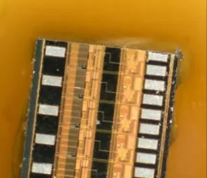
Silicon Die: Die made of silicon with dimensions: 2.79 mm x 1.49 mm x 0.68 mm were used.
Gold-plated Ceramic Housing: Housing made up of ceramic material, Alumina (Al2O3) on top of which Gold layer of thickness 9 μm is deposited was used.
Weigh Balance:
Needles and Tweezers
Fig. 1: Weigh balance in Fabrication Lab.
Adhesives: Four potential candidates were chosen depending on requirements from our application, which are:
1. EPO-TEK H70E from Epoxy
Technologies
Two component paste adhesive
100% solid
Epoxy based with Alumina-fillers
Electrically insulated but thermally conductive.
Beige Colour
2. EPO-TEK H20E from Epoxy Technologies
Two component paste adhesive
100% solid
Epoxy based with Silver-fillers
Electrically as well as thermally conducting adhesive.
Silver colour
3. SurABond HS25 from SurA Chemicals
Two component paste adhesive
Solvent Based Adhesive
Epoxy based with inorganic fillers
White colour
4. Stycast 2850 FT with Catalyst 24LV from Emerson and Cumings
Two component paste adhesive
Solvent Based Adhesive
Epoxy based with inorganic fillers.
High thermal conductivity (>1 w/mK) and successful application at cryogenic temperatures.
Black colour
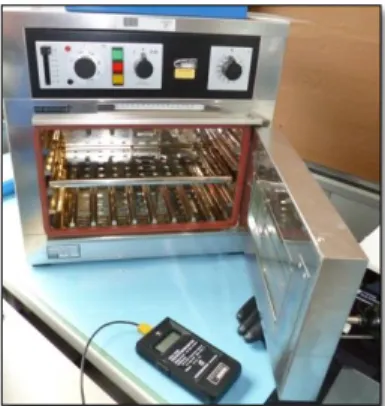
Oven and Thermocouple:
3.2.2. Adhesive Bonding Procedure:
When ready to use, Part-A was weighed.
Part-B was then weighed proportionate to the weight of Part-A as per recommended mixing ratio by the company.
After weighing, the two parts were mixed properly for 2-3 minutes. Avoid high mixing speeds which could entrap excessive amounts of air or cause over-heating.
Die and bonding surfaces were cleaned prior to bonding with highly polar solvent, ethanol using swabs/tissues. Ethanol is easily vaporized, leaving the surfaces and electronic components dry. Cleanliness and chemical and physical condition of the surfaces assure good adhesion. Inadequate cleaning prevents or reduces adhesion and residues can cause corrosion over time.
Fig. 2: Oven used for curing and thermocouple in Fabrication Lab.
3.3. General Description of Tests Performed:
3.3.1. Testing the Shelf Life:
In order to test the effect of Shelf life, two bottles of same adhesives (H70E) were taken:
Expired H70E, whose shelf life is over in Febuary’2012 and New H70E, which is manufactured in Febuary’2013. Samples were prepared from both H70E adhesives using above described preparation methods. The prepared samples were given repeated cycles of LN2 (as described below), which were then examined under microscope and with die-shear force machine.
Adhesive was dispensed on the substrate by forcing it through a needle. The pin was dipped into uncured adhesive, and then removed taking with it suspended drops of adhesive. The pin was then lowered onto the substrate and the adhesive was transferred to it.
The die was picked up manually using a tweezers and placed on the adhesive. Gentle pressure was applied to the die.
After dispensing, the adhesive was heat cured in oven for recommended time and temperature as per the technical sheet, where it goes into solid state from semi-solid with full development of its adhesive strength and dielectric.
3.3.2. Varying Curing Schedule and Cooling Technique:
Samples were prepared following the different curing time-temperature combinations in order to examine their effect on adhesive bond strength.
Samples after curing at different temperatures for various different time intervals were cooled in two different ways:
Slow and uniform cooling where the samples were kept in the oven for 12-16 hours or so until it reaches room temperature within oven itself.
Fast and Non-uniform cooling where the samples were taken out of the oven immediately after the curing is complete
After cooling they were given repeated LN2 cycles, and analysed by visual inspection and die-shear force testing to compare their bond strengths.
3.3.3. Liquid Nitrogen (LN2) Tests:
Extreme thermal shocks were given from +25 °C to -196 °C i.e. with 220 °C of thermal gradient. They were given in 4 separate ways which are as follows:
3.3.3.1. Repeated LN2 cycles at an interval of 10 minutes:
The specimens were kept in an oven at different temperatures for different time intervals and then immersed in LN2 bath at -196 °C. As soon as the sample was put into the bath, it started bubbling. When the bubbling stopped (which means that the sample had acquired the LN2 temperature), the sample was taken out and kept at RT for 10 minutes, so that it acquired RT. After 10 minutes it was again put into LN2 bath for 2nd cycle. The whole process was repeated for more number of cycles.
3.3.3.2. Long immersion in LN2 for 2 days:
The prepared samples were put into LN2 bath for continuous 2 days without disturbing the bath. After 2 days samples were taken out for visual inspection and die-shear force tests.
3.3.3.3. Long immersion in LN2 for 8 days:
Same procedure as above, the only difference was duration of sample’s dip into LN2 was 8 days.
Fig. 3: LN2 along with safety equipment in HEC Lab.
3.3.4. Testing the Soldering Conditions:
With the trend toward eliminating lead in solder pastes, new no-lead solders are being introduced that require even higher reflow temperatures.
Soldering can be performed in two ways:
Hand Soldering: Where the temperatures encountered for Pb-Sn solder is 340 °C and for Pb- free solder is 370 °C for 2-3 seconds. Since the time for such high temperature is very small, it doesn’t hamper adhesive properties at all.
Solder Reflow: The temperatures faced are 200 °C for Pb-Sn solder and 230 °C for Pb-free solders for 2-4 minutes. Such prolonged exposure to such high temperatures causes absorbed moisture in the adhesive to rapidly vaporize producing stresses and delaminations within the sample.
Hence the behaviour of adhesives was tested at soldering temperatures of 200 °C, 230 °C, 270 °C for prolonged time of 2, 4 and 6 minutes each. After the treatment, the samples were visually inspected without and with LN2 treatment.
3.4. Analysis of Tests Performed:
3.4.1. Microscope:
A binocular microscope with magnification capabilities of 5x minimum and lighting for facilitating the visual observation of the die and adhesive layer was required.
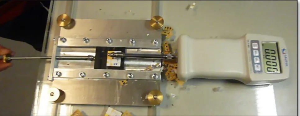
3.4.2. Die Shear Test:
The purpose of this test was to determine the integrity of attached dies to the substrate.
This determination was based on measurement of force applied to the die; the type of failure resulting from this application of force (if failure occurs) and the visual appearance of the residual die and substrate.[2] Mechanical reliability of the bonds for die and substrate
Fig. 4: Microscope in the Fabrication Lab.
attachment was determined by comparing die-shear strength of before and after the exposure to severe environmental conditions.[1]
Apparatus: The test equipment consisted of a load-applying instrument as shown below.
Following precautions should be taken throughout the test:
Fig. 7: Die contact tool should apply a uniform force to an edge of the die.
Fig. 8: Die contact tool should always be perpendicular to edge of the die.
Fig. 5: Die-shear force machine constructed in Mechanical Workshop.
Fig. 6: Schematic of the die-shear test.[8]
[Ref: “IPC-TM-650 Test Methods Manual”, The Institute for Interconnecting and Packaging Electronic Circuits, Northbrook, 1998.]
Procedure: A force sufficient to shear the die from the adhesive or equal to twice the minimum specified shear strength in the technical datasheet of the adhesive, whichever occurs first, was applied to the die using apparatus discussed above. Sometimes the tool rode over the die, in that case, the die can be substituted or repositioned. The direction of the applied force should be parallel with the plane of the substrate and perpendicular to the die being tested. Minimum force in kilograms (kgs) required to detach the die was recorded.[2]
Note: The force for shearing is based on the area of the die being used. With change in the area of the die, the shearing force value also changes.
3.5. Failures, Fractures and Phenomena Occurring:
During various experiments performed throughout the project, following failures and phenomena were observed. Their description is given here to avoid repetitive discussions later during results.
3.5.1. Loss of Adhesion (delamination):
Loss of adhesion or loss of mechanical strength is the most unacceptable phenomenon in bonded samples. There are two types of failures which may be responsible:
Cohesive failure (catastrophic failure) which occurs within the adhesive. The strength of the adhesive is less than the forces applied to it and thus the adhesive pulls apart leaving portions of the adhesive bonded to both substrates.[8] Cohesive failure is independent of bond thickness.[9]
Adhesive failure at the bond line interfaces (laminar failure). In this failure, the adhesive completely loses its bond to the substrate. This occurs when the adhesive strength of the adhesive is lower than its cohesive strength.[8] Adhesive failure depends on bond thickness.[9]
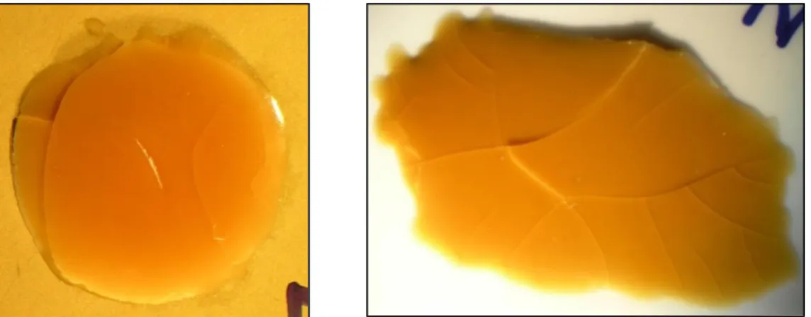
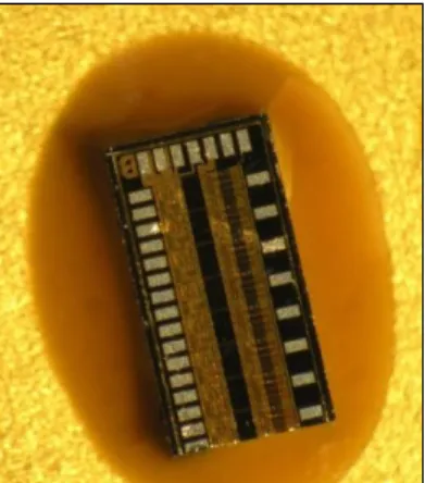
The two pictures below show adhesive and cohesive failures respectively obtained during one of experiments with H70E adhesive. The picture on the left has metal substrate, which mostly showed adhesive failure whereas the ceramic substrate (picture on right) showed mostly cohesive failure. The reason is described below:
The mechanism with which the die fails depends largely on the curing schedule. If the temperature and time for cure is not sufficient, the strength of the adhesive is not fully developed. Hence the cohesive strength of the adhesive remains less than the adhesive strength. But if the temperature is higher than required, overheating cause excess hardening of the adhesive layer and increases its cohesive strength. In case of metal, the heat transfer rate to the adhesive layer is very fast due to its high thermal conductivity whereas adhesive layer on ceramic substrate is left unhardened due to insufficient heat transfer due to its poor thermal conductivity. And thus the cohesive strength of metal- adhesive is much higher than ceramic-adhesive sample.
As per our required cryogenic applications of the adhesives it is necessary to maintain adhesion strength after repeated LN2 thermal cycling, elevated-temperature exposure during soldering, or temperature–humidity exposure.
Complete detachment of the die from the substrate leads to immediate failure of the component while partial debonding results in die or substrate cracking followed by complete detachment after some time. Numerous factors and mechanisms contribute to delamination, some of which are as follows:
Since all four adhesives we used were two-part adhesives, non-stoichiometric mixing ratios of resin (Part-A) to hardener (Part-B) can lead to poor strength.
Insufficient cleaning leaves surface contaminants which enhances bleedout.
Non-uniform adhesive coverage decreases area of contact between die and adhesive and thus gives low strength.
Non-uniform or insufficient pressure in applying film adhesives can result in tilting of the die and thus affects bond strength.
Fig. 10: Optical image of H70E applied to gold substrate and ceramic plate to demonstrate cohesive and adhesive failure respectively.
Insufficient cure time or temperature leaves unreacted resin or hardener; or excessive cure conditions, results in embrittlement.
Stresses generated at cryogenic temperatures due to large mismatches in the CTEs of the adherends have a huge impact in lowering the mechanical strength.
Adhesives having too high or too low modulus for the size of the device.
Voids in the bond line due to entrapped air, moisture, solvents, or volatile compounds.
Large amounts of absorbed moisture in the adhesive layer.
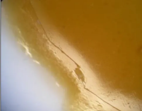
3.5.2. Excessive wetting and bleedout:
The separation and migration of adhesive constituents is known as bleedout. Bleedout can be easily visualized as a slight discolouration of the surface around the adhesive joint and may occur prior to or during cure. Bleedout is common with two-part filled epoxy adhesives where one ingredient migrates and contaminates the adjacent area. This contamination results in a decreased bond strength.[1]
Two main reasons contribute to resin bleedout:
1. Surfaces which have very high surface energies e.g. metal and ceramic, increase bleedout, because adhesive resin acquires stronger affinity to the substrate surface than to its own fillers. Smooth, uniform surfaces bleed less; grainier, porous surfaces due to capillary action and extremely clean surfaces due to high surface energies promote bleedout.
2. Another reason for bleed out is surface contamination. This contamination can appear from ample sources in manufacturing and handling processes. Thus the solution to bleed out as suggested by James E. Ireland[5] is Vacuum Baking for a specific time (which depends on the adhesive type) at 250 °C.
Remedy: Thinner layers of the adhesive were found to bleed severely. The proof can be seen in the picture below with H70E on Gold substrate after heat curing:
The separation of resins in this case occurred immediately after dispensing of the adhesive.
Heat provided during the curing caused the separated resin part to spread out more rapidly radially outwards as seen in above picture, causing an actual physical collapse of original layer which is no more visible clearly!
One of the remedies to prevent bleedout in epoxy resins is to find the optimal range of coating thickness while maintaining adhesive bond strength. This optimum coating thickness range is extremely narrow and sometimes even difficult to pinpoint. If coating thickness lies slightly outside this range, one will lose significant bond strength or experience heavy resin bleed.[12]
3.5.3. Adhesive coverage:
Dispensing insufficient adhesive to cover the entire bond line can result in poor strength. A visible fillet around two or more sides of an attached die or substrate provides assurance that sufficient adhesive has been used and has covered the entire bond line. According to few military standards, at least 75% of the fillet should be visible along each side of the device. Applying a uniform thickness is also important. Non-uniform thicknesses result in tilted devices with the potential for cracking and separation.[1]
Experiments were performed to see the effect of changing area of contact on bond strength. The results will be discussed later.
3.5.4. Voids and moisture absorption:
Voids can appear in the adhesive layer at various stages of the whole process. Voids are not only detrimental to mechanical strength but hampers thermal performance of the device due to entrapped air.
They can be generated during die-attach process due to entrapment of air, or volatilization of absorbed gases during curing. They can also appear during cool-down from heat curing, resulting in shrinkage with separation from the substrate.
Moisture absorbed by the adhesives gets accumulated in voids within the bond line. This absorbed moisture in adhesive layers cause failures at solder-reflow temperatures of 200 °C and above.
Some measures generally taken to prevent voids are use of low-moisture-absorption adhesives, degassing adhesives prior to cure, prebaking the components to remove adsorbed moisture, and step curing at low temperatures to allow air and volatiles to escape before full cure.
3.5.5. Failures during Soldering (Popcorn Effect):
Popcorn effect is a kind of failure in the adhesive layer which occurs due to rapid release of absorbed water in adhesives on exposure to the high solder-reflow temperatures. The
solder-reflow is done at high temperatures (220–240 °C) for 2-4 minutes. Such prolonged exposure to such high temperatures causes absorbed moisture in the adhesive to rapidly vaporize producing stresses and delaminations. This phenomenon is called popcorning because of the crackling sound heard during the reflow step.[1]
To avoid this effect, the adhesives with low moisture absorption, high thermal stability, and low stress should be used.
3.5.6. Fillet size and cracks into fillets:
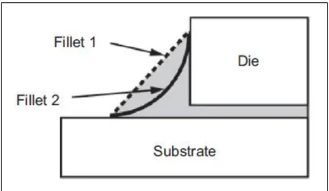
The adhesive surrounding the periphery of the die forms Fillet. Fillets are necessary to dampen vibration and shocks occurring to the die. They accommodate the strains induced during thermal cycling due to mismatch in CTE of substrate and die. Also a visible fillet around the sides of the die confirms complete area coverage below the die with the adhesive.
Depending on the amount of adhesive dispensed and the pressure applied on the die after dispensing, the fillets can be thin or thick. Thin and thick fillets are relative terms.
Fillet-1 in Fig. 12 is thick fillet which has more amount of adhesive in the surrounding region than Fillet-2 which is thin fillet. Fillet-1 will provide better support and stress absorbance but needs more time and temperature for complete curing. This extra temperature and time can over-cure the surface layers of the adhesive which is detrimental. Fillet-2 will not provide as good support as Fillet-1 but cure completely in time with other regions of the adhesive layer. Hence an optimization for the amount of adhesive to be used is necessary in order to prevent too thick or too thin adhesive layers.
Fig. 12: Different shapes of fillets formed depending on amount of adhesive used and pressure applied.[1]
3.5.7. Presence of Notches and Cracks:
Another major defect observed during the experiments was development of notches around the die. These notches were clearly visible in the adhesive region around the die.
They had sharp tips from where cracks were being originated.
Cracks generally originate from a stress raiser spot or from a place where stress concentration is very high e.g. corners of the die have high stress concentration due to their triaxial state and therefore most cracks were originated from the corners only (can be seen in the pictures from the experiments in later part of this report). Hence, crack origination from the tips of notches implies that notches in the adhesive layer act as high stress raisers points and are highly detrimental to mechanical strength of the adhesive.
Another important feature which was noticed about notches is that they always develop in the sample which was given fast and non-uniform cooling followed by LN2 cycles i.e. high thermal gradients which produces high thermal stresses seems to be the reason for notch development in an adhesive sample.
3.5.8. Uncured Part of Adhesive:
One more important defect observed was presence of “Uncured Part of the Adhesive”.
Insufficient curing time and temperature and fast cooling leaves behind unreacted resin or hardener in the adhesive region. This unreacted part adversely affects the electrical, physical, or thermal properties of the adhesive causing:
1. Loss in Adhesion.
2. Reduced bond strengths.
3. Increased moisture absorption.
4. Lower electrical values.
5. Greater outgassing.
Thicker fillets had more uncured part than thinner fillets because more amount of adhesive requires more time and temperature to get fully cured.
3.5.9. Spread out of adhesive at Soldering temperature:
Spreading out of the adhesive during soldering experiments was very common at higher temperatures and during longer exposure time periods. Keeping adhesives at higher temperatures for longer time decreases their viscosity and they start to flow. The spreading of adhesive seen in our experiments was very high, flowing over huge near-by areas. This could contaminate adjacent assemblies and hamper the working of the device.
3.5.10. Effect of thickness:
The effort was made to study effect of thickness on bond strength. However, no relation between both the quantities could be established. Layers with thicknesses varying from 5 to 200 μm were prepared but found to have no correlation with the bond strength and crack origination.
SECTION 4 TESTS WITH H70E
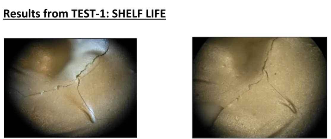
4.1. Results from TEST-1: SHELF LIFE
Uncured H70E had beige colour but after curing at 80°C for 1.5 hours gives Caramel colour as shown below.
After the samples are prepared from Expired and New H70E, they were given 1st cycle of LN2. Results are shown below:
H70E: After 1st cycle of LN2
As seen in above picture for Expired H70E, adhesive shows cohesive failure (catastrophic breaking). The fracture lines are intense and deep and spread all over the adhesive layer.
This shows very low cohesive strength among the adhesive particles.
In addition to cohesive failure as shown above, expired H70E shows laminar fracture or adhesive failure too as seen in the picture on the left. This type of fracture shows very poor adhesive strength.
Fig. 15: Optical image of NEW H70E applied to ceramic substrate.
Fig. 14: Optical image of EXPIRED H70E applied to ceramic substrate showing cohesive failure.
Fig. 16: Optical image of EXPIRED H70E applied to ceramic substrate showing laminar cracks.
Fig. 13: Optical image of H70E before and after heat cure showing colour change.
Expired H70E: After 2nd cycle of LN2
New H70E: After 1st and 2nd cycle of LN2
New H70E showed no cracks even after two cycles of LN2. The first picture in Fig. 19 has very less amount of adhesive surrounding the die i.e. thin fillets while second picture shows large Here we can see cracks originating from the corners of the die. Since the corner has maximum stress concentration, most of the cracks originate from corners only.
After 2nd cycle of LN2, the adhesive ripped off from the surface. Although in the die sample, no significant impact on the crack growth was seen after 1st cycle.
Fig. 17: Optical image of EXPIRED H70E applied to die showing cracks from the corners.
Fig. 18: Optical image of EXPIRED H70E applied to ceramic substrate after 2 cycles of LN2.
Fig. 19: Optical image of NEW H70E applied to die sample after 2 cycles of LN2 with thin and thick fillets respectively. *Thickness of adhesive layer=50 μm for both samples.+
and thick fillets. But here, neither the thin nor thick fillets have cracks, although the thickness of adhesive layer is 50 μm in both the samples.
Note: Fillets should not be confused with thickness of the adhesive layer. Thickness of adhesive layer is 50 μm in both the samples above but amount of fillets surrounding the dies are different.
4.2. Results from TEST-2: Varying Curing Schedule and Cooling Technique:
The samples were cured at different temperatures for various different time periods followed by slow and uniform cooling or fast and non-uniform cooling. After cooling, LN2
cycles were given repetitively followed by visual inspection and die-shear tests. For H70E, following conditions were chosen:
Temperature: 70-75 °C or >= 80 °C
Time: 1 Hour or 1.5 Hours
Cooling Technique: Slow and Uniform or Fast and Non-uniform.
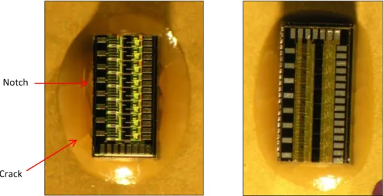
4.2.1. Temp: 70-75°C, Time: 1 Hour, Fast and Non-uniform Cooling
At the given conditions of curing and cooling, notches were developed around the die and cracks originated from the tips of these notches (as seen in above pictures). Severe cracks in both the above samples can be seen, but the die having thicker fillets of adhesive shows more severe cracks distributed all around the die than thinner.
Also uncured part in the adhesive was seen as the white portion in the adhesive region. This was due to insufficient curing time and temperature and fast cooling. Thicker fillets showed more uncured part than thinner parts.
Fig. 20: Die samples having thick and thin fillets of H70E respectively showing notches and cracks.
Notch
Crack
4.2.2. Temp: 70-75 °C, Time: 1 Hour, Slow and Uniform Cooling
The curing schedule in this case is same but cooling is very slow and uniform as compared to above case. This kind of slow cooling prevents high thermal stresses. Visual inspection of the samples under microscope at 10x magnification did not show considerable number of notches, which means very less severity of cracks too. Although uncured was visible under microscope.
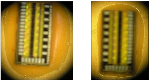
4.2.3. Temp: 70-75 °C, Time: 1.5 Hours, Fast and Non-uniform Cooling
Uncured Part
Bleed Out
Notches can be seen in Fig. 23. This proves fast cooling generate thermal stresses inside the adhesive layer which are responsible for development of notches. There was also uncured part of adhesive visible under microscope, although it was not very distinguishable in the pictures.
Another major defect found in this case was “Bleed Out” as discussed before (Fig. 22). The separation of resin formed a ring around the adhesive layer and application of heat causes this separated material to spread rapidly radially outward.
Fig. 21: Die sample showing uncured part of H70E (white region).
Fig. 22: Die sample showing bleed out in H70E (transparent layer).
4.2.4. Temp: 70-75 °C, Time: 1.5 Hours, Slow and Uniform Cooling
This case had more curing time than first two cases; also the cooling was slow and uniform.
The pictures taken from microscope did not show any notches, cracks and bleed out. There was slight uncured part which was visible only at very high magnification.
4.2.5. Temp: >= 80 °C, Time: 1 Hour, Fast and Non-Uniform Cooling
Curing temperature is higher than before. Due to fast cooling, again few notches can be seen in Fig. 25. However, the severity and amount of notches developed in this case is very less than before.
Fig. 24: Die sample with H70E with thick and thin fillets respectively.
Fig. 25: Die sample with H70E showing few notches.
4.2.6. Temp: >= 80 °C, Time: 1.5 Hours, Slow and Uniform Cooling
4.2.7. Snap Curing - Temp: 120 °C, Time: 15 Minutes, Slow and Uniform Cooling
The sample showed none kind of defects and had very high die shear strength as well. But according to many literatures, it is recommended to choose lower temperature if maximum bond strength is desired because it minimizes the effect of CTE mismatch in adhesive and substrates in cooling to ambient conditions from the cure.[6]
The results from the tests carried out by varying curing schedules and cooling techniques are summarized in the table below with their acceptability for our application.
S.No Curing
Temperature
Curing Time Cooling Technique
Acceptability Die-shear strength
1 70-75 °C 1 Hour Fast WORST Very high
2 70-75 °C 1 Hour Slow WORSE Very high
3 70-75 °C 1.5 Hours Fast BAD Very high
4 70-75 °C 1.5 Hours Slow GOOD Very high
5 80 °C 1 Hour Fast NOT GOOD Very high
6 80 °C 1 Hour Slow VERY GOOD Very high
8 80 °C 1.5 Hours Slow BEST Very high
9 120 °C 15 Minutes Slow BEST but Not
Recommended
Very High
After finding the most suitable method for curing, further tests were performed following that curing schedule only.
Curing schedule in this case is the one recommended by the company. In Fig. 26, no uncured part or bleed out was seen. Also since the cooling was slow and uniform, no notches developed and hence no cracks. This curing schedule is the most suitable for preparing crack- free samples with H70E.
Fig. 26: Die sample with H70E without any defects.
Table.1: Results summarized for Curing Schedules and Cooling techniques for H70E.
4.3. Results from TEST-3: Long immersion in LN2 for 2 days
The samples were taken out of the LN2 bath after 2 days continuous immersion, showed no cracks at all, but there were notches present around the die. The presence of notches can be explained because of thermal stress being generated inside the sample due to long immersion in LN2. But since there were no thermal cycles given to the sample, cracks were absent. This means cracks originate if repetitive thermal shocks are given to the sample.
4.4. Results from TEST-4: Long immersion in LN2 for 8 days
4.5. Results from TEST-5: Die-Shear Test
Die shear strength of all the samples prepared at various curing schedules with both the cooling techniques was very high. Adhesive layer didn’t fracture even at loads > 10 kgs (which is the maximum capacity of the die-shear instrument).
Die shear strength of the samples taken out of the LN2 bath after long immersion was also very high (> 10 kgs).
If any major impact on shear strength of the adhesive has to occur, it occurs between room temperature to -196 °C. From -196 °C and -253 °C there is no significant change.[6] Hence an adhesive able to survive at LN2 temperatures will definitely survive at much lower temperatures too maintaining its shear strength.
Samples taken out of LN2 bath after 8 days showed similar results as above.
There were notches present but no cracks. Dies with thin fillets did not even showed notches around.
Fig. 27: Die sample with H70E after 8 days of long dip in LN2.
4.6. Results from TEST-6: Soldering Conditions
4.6.1. At 200 °C
4.6.2. At 230 °C
4.6.3. At 270 °C
After 2 minutes of heating at 200 °C, the
“shrinkage/waviness” of the adhesive layer seen in Fig. 28 is due to popcorn effect. This effect was more pronounced in dies with thick fillets than thinner ones.
After 4 minutes of heating at 270 °C, huge After 6 minutes of heating at 270 °C, After 2 minutes of heating,
colour became darker and popcorn effect started to appear only in thick fillets.
After 4 minutes of heating, colour became much darker and popcorn effect more pronounced in thick as well as thin fillets.
After 6 minutes of heating, very dark colour of the adhesive and along with popcorn effect adhesive started to flow and spread out on adjacent areas.
Fig. 28: Die sample with H70E after heating at 200 °C for 2 minutes showing popcorn effect.