Analyzing Interacting BPEL Processes
?Niels Lohmann, Peter Massuthe, Christian Stahl, and Daniela Weinberg
Humboldt–Universit¨at zu Berlin Institut f¨ur Informatik
Unter den Linden 6 10099 Berlin, Germany
{nlohmann, massuthe, stahl, weinberg}@informatik.hu-berlin.de
Abstract. This paper addresses the problem of analyzing the interac- tion between BPEL processes. We present a technology chain that starts out with a BPEL process and transforms it into a Petri net model. On the model we decide controllability of the process (the existence of a partner process, such that both can interact properly) and compute its operating guideline(a characterization of all properly interacting partner processes). A case study demonstrates the value of this technology chain.
Key words:Business process modeling and analysis, Formal models in busi- ness process management, Process verification and validation, Petri nets
1 Introduction
To an increasing extend interorganizational cooperation is crucial for enterprises to meet the new challenges of ever faster changing business conditions and the growing number of competitors in all kinds of business fields.
In this context, services play an important role: they serve as the basic building blocks of such interorganizational cooperations. Recent publications apply the term service in different contexts with varying denotations (see [1]
for a survey). A common understanding is that a service basically encapsulates self-contained functions that interact through a well-defined interface via asyn- chronous message passing.
A service can typically not be executed in isolation – services are designed for being invoked by other services, or for invoking other services themselves. The interaction of services is described by the paradigm ofservice-oriented comput- ing (SOC) [2]. Thereby, two different approaches can be distinguished: service orchestrationsconsider one particular service that directs the logical order of all other services, whereas service choreographies consider the case where individ- ual services work together in a loosely coupled network. The participants of such interactions are called partners.
The most common implementation of services areweb services. TheBusiness Process Execution Language for Web Services(BPEL, also known as WS-BPEL
?Partially funded by the BMBF project “Tools4BPEL”.
or BPEL4WS) [3] is an accepted language to describe web services. We shall refer to a web service that is described in BPEL as a BPEL process or process for short.
A choreography of BPEL processes may cause nontrivial interaction between them. Thus it is a challenging task to decide whether the whole choreography of processes interacts properly, i. e. it is free of deadlocks and there are no messages being sent that cannot be received any more. There are two main reasons for non-proper interaction: (1) a process may have an erroneous design. For instance, the process may contain an internal choice relevant for the expected behavior of a partner, but the partner is not informed which decision is actually made; (2) the interactional behaviors of two processes of the choreography exclude each other. For example, the processes run into a situation where one process waits for a message of the other one and vice versa.
Thus a BPEL process needs to be analyzed thoroughly before it is deployed.
For this purpose, we can make use of several results in the context of the analysis of services and of backing BPEL processes with a formal semantics. In [4] the notion of controllability was developed. A service is controllable if there exists a partner such that both interact properly. Thus an erroneous design of a ser- vice itself is detected by analyzing its controllability. We further developed the operating guideline of a service. The operating guideline characterizes all prop- erly interacting partners in a compact way [5]. With the aid of the operating guideline it can be checked whether the interactional behaviors of two services exclude each other. As a formal model for BPEL processes open workflow nets (oWFNs) [6], a special class of Petri nets, are used. Further, we developed a feature-complete Petri net semantics for BPEL [7]. The semantics allows for an automatic transformation of BPEL processes into Petri net models [8]. The resulting Petri net models are well-suited for computer-aided verification. The verification, however, is restricted to the internal behavior of a BPEL process so far and does not consider the interactional behavior.
BPEL2oWFN BPEL
process
pattern repository
Petri net (PNML, LoLA, PEP, APNN)
model checkers (CTL, LTL, deadlocks)
open workflow net Fiona
(controllability, OG)
Fig. 1.Proposed tool chain to analyze BPEL processes.
In this paper we extend the analysis of BPEL processes presented in [8]
by interactional behavior. We introduce two tools – BPEL2oWFN and Fiona.
BPEL2oWFN transforms a BPEL process into an oWFN. That way it is possi- ble to analyse the interaction between BPEL processes with Fiona, a tool that decides controllability and computes the operating guideline. Thus, we present a technology chain (Fig. 1) that starts out with a BPEL process, transforms it into an oWFN or a Petri net and that finally analyses the process by either using
Fiona or by using a common model checker. Throughout this paper we restrict ourselves to the interaction of two processes only. For the interaction of more than two processes, some theoretical results [9] exist, which are not implemented yet.
The rest of the paper is organized as follows: in Sect. 2, we provide an overview of the general concepts of BPEL and introduce our model, open work- flow nets. We also explain controllability of oWFNs and operating guidelines for oWFNs. A BPEL example process, an online shop, is presented in Sect. 3.
Section 4 explains the concepts of our advanced transformation and translates the online shop into an oWFN. The resulting oWFN is then analyzed in Sect. 5.
We present a slightly modified version of that process in Sect. 6 and analyze it, too. In Sect. 7 we describe related work in detail. Finally, we conclude with directions to future research.
2 Background
2.1 BPEL
The Business Process Execution Language for Web Services (BPEL) [3], is a language for describing the behavior of business processes based on web ser- vices. For the specification of a business process, BPEL providesactivities and distinguishes between basic and structured activities. A basic activity can com- municate with the partners by messages (invoke1,receive,reply), manipulate data (assign), wait for some time (wait) or just do nothing (empty), signal faults (throw), or end the entire process instance (terminate).
A structured activity defines a causal order on the basic activities and can be nested in another structured activity itself. The structured activities include se- quential execution (sequence), parallel execution (flow), data-dependent branch- ing (switch), timeout- or message-dependent branching (pick), and repeated execution (while). The most important structured activity is a scope. It links an activity to a transaction management and provides fault, compensation, and event handling. Aprocess is the outmost scope of the described business pro- cess.
A fault handler is a component of a scope that provides methods to handle faults which may occur during the execution of its enclosing scope. Moreover, a compensation handler can be used to reverse some effects of successfully exe- cuted activities. With the help of an event handler, external message events and specified timeouts can be handled.
2.2 Open Workflow Nets
Open workflow nets (oWFNs) [6] are a special class of Petri nets and can be seen as a generalized version of van der Aalst’s workflow nets [10]. As a substantial difference, in an oWFN the interface of a service is explicitly represented as sets
1 We use a typewriter font for BPEL activities.
of input and output places. In our model we concentrate on control flow aspects of services and abstract from data (like, e. g., the content of messages). For data with finite domain, however, important message content can be represented in our approach. For instance, a channel receiving messages with Boolean values can be represented by its separation into two channels: one for messages with content true and one for messages with content false. Hence, oWFNs provide a simple but formal representation of services, still preserving sufficient information to analyze proper interaction of such services.
We assume the usual definition of Petri nets. Anopen workflow net is a Petri netN = (P, T, F), together with (1) aninterface I=in∪outsuch thatI⊆P, in∩out = ∅, and for all transitions t ∈ T it holds: if p ∈ in (p∈ out), then (t, p)∈/ F((p, t)∈/F), (2) a distinguished markingm0, called theinitial marking, and (3) a setΩof distinguished markings, called thefinal markings. The places in in (out) are called input (output) places. The inner of an oWFNN can be obtained from N by removing all interface places, together with their adjacent arcs. As a convention, we label a transition t connected to an input (output) placexwith ?x(!x).
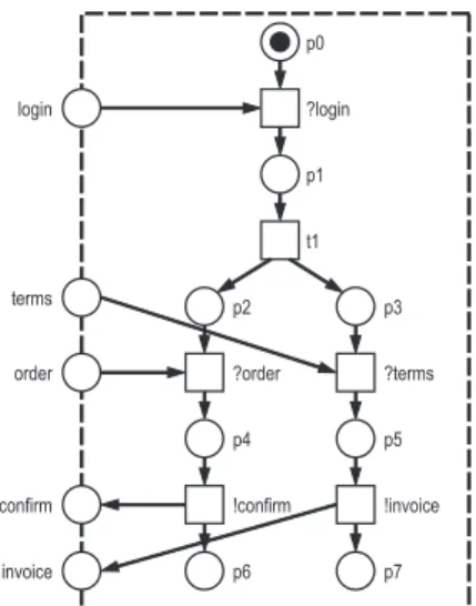
Throughout this paper we only consideracyclicopen workflow nets, i. e. nets where the transitive closure of F contains no cycles. As an example, consider the oWFNN1depicted in Fig. 2.
Fig. 2. An example oWFN N1. The net has three input places, login, terms, and order, and two output places,confirmand invoice. The ini- tial marking m0 is [p0] which denotes one to- ken on placep0.N1 has only one final marking, [p6,p7].
Inm0the net waits for the login message from a partner. If the message arrives, transition?login can fire and produces a token on placep1.
Then, firing transition t1 yields the marking [p2,p3]. This means that the net is ready to con- currently receive an order message (order) and a terms of payment message (terms). The order is confirmed (!confirm) and the terms of payment are followed by an invoice (!invoice). If both tran- sitions have fired, the final marking [p6,p7] is reached.
p0
p1
p2
?login
t1
?order login
p3
?terms
p4
!confirm
p5
!invoice order
p6 p7
terms
confirm
invoice
The interplay of two oWFNsN andM is represented by theircomposition, denoted by N ⊕M. Thereby, we demand that the nets only share input and output places such that an input place of N is an output place of M and vice versa. The oWFNN⊕M can then be constructed by merging joint places and merging the initial and final markings. Merged places become internal toN⊕M.
A marking (sometimes called astate)mofNis called adeadlock ifmenables no transition. An oWFN in which all deadlocks are final markings is calledweakly terminating. Obviously, the netN1 in Fig. 2 itself isnot weakly terminating.N1 requires a partner who sends and receives messages.N1 is not able to reach its final marking [p6,p7] on its own. Given an oWFN N, we call an oWFN S a strategy forN iffN⊕S is weakly terminating.
2.3 Controllability of oWFNs
Intuitively, controllability of an oWFN N means that N can properly interact with some other net. Formally, N is controllable iff there exists a strategy for N. Like the soundness property for workflow nets (cf. [10]), controllability is a minimal requirement for the correctness of an oWFN.
In [4] we developed an algorithm to efficiently decide the controllability of an oWFN N. Intuitively, the algorithm tries to construct (synthesize) a strategy, i. e. an oWFNS, which imposes the weak termination property ofS⊕N. If the construction fails,N is not controllable. If it succeeds,N is controllable and we have constructed a strategy,S. This construction is, in fact, a problem known in the literature ascontroller synthesis (see [11]). Technically we do not construct a strategy S, i. e. an oWFN, but an automaton that reflects the interactional behavior of S instead. To avoid confusion, we call the constructed automaton controller, but denote it withS as well.
To construct such a controller S, we first construct the interaction graph (IG) ofN which has also been introduced in [4]. The IG represents a controller’s point of view of N. A node of the graph represents the set of all states that N can reach by consuming (already present) messages or producing messages itself. The actual state of N is hidden for S. S knows the history of sent and received messages only. From that information, in each node,Scan deduce aset of states of N whichcontains the state that N is really in. Thus a node of the graph represents a hypothesis of the controller with respect to the actual state ofN.
S can control the net in a limited way by sending or receiving messages.
Each edge of the graph represents anevent ofS. Asending event (labeled by!) means that S sends a message to N. The new message may enable N to fire previously disabled transitions, i. e. deadlocks may get “resolved”. A receiving event (labeled by?) ofS represents the receiving of a message by the controller.
Thereby, the controller gets some more knowledge about the state thatN might be in.
In the constructed IG, we then look for a controllerS forN. The controller is a subgraph of the IG containing the root node and fulfilling the following property: for every node v of the subgraph and each deadlock inv which is no final marking, there exists an event atvthat resolves that deadlock and leads to a node of the subgraph again. This property can easily be checked while the IG is constructed. The oWFN is controllable iff such a controller can be found. In a final step, the controller could be transformed into an oWFN by using the theory of regions [12], for instance. This oWFN is then a strategy by construction.
Fig. 3.The IG for the netN1of Fig. 2. The first node of the IG represents the hypothesis that the controller ofN1 has about N1 when neither messages have been sent nor received: the net must be in state[p0], which is a deadlock. Hence, the first node contains the state[p0]only.
However, sending a login message resolves the deadlock. Hence, we add an edge labelled with the sending event !loginand a new (yet empty) node to the IG.N1 is now in state[p0,login]and may fire transition?loginreaching the state[p1].
After successively firing all enabled transitions the next reachable deadlock is [p2,p3]. So the new node contains the states[p0,login],[p1], and [p2,p3].
Now one of two sending events is possible:!order or !terms. So we add two edges and two empty nodes, and so on.
The last node of the controller represents the states where N1 can be in after all the mes- sages are exchanged. There is only one deadlock, [p6,p7], in that node which is the final marking ofN1.
[p0]
[p0, login]
[p1]
[p2, p3]
!login
[p0, login, order]
[p1, order]
[p2, p3, order]
[p3, p4]
[p3, p6, confirm]
!order
[p0, login, terms]
[p1, terms]
[p2, p3, terms]
[p2, p5]
[p2, p7, invoice]
!terms
[p3, p6]
?confirm
[p3, p6, terms]
[p5, p6]
[p6, p7, invoice]
!terms
[p6, p7]
?invoice [p2, p7]
?invoice
[p2, p7, order]
[p4, p7]
[p6, p7, confirm]
!order
?confirm
As an example, the IG of the oWFN N1 (see Fig. 2) is depicted in Fig. 3.
As we can see in the IG of N1 each deadlock in any node (except for the final marking in the last node) is resolved. Hence, the IG itself represents a controller, and we conclude that N1 is controllable. Please note that two other subgraphs constituting controllers can also be found in the IG ofN1.
2.4 Operating Guidelines for oWFNs
The IG of an oWFNN contains onlysomecontrollers ofN. For a representation of all controllers (all properly interacting partners) of N, the concept of the operating guideline (OG) for N was introduced in [5]. As we did in the section before, we do not directly represent the strategies as oWFNs, but represent their behaviors as automata.
The OG ofN is constructed as follows: in a first step, an extended interaction graph forN is computed which considers more events than the original one. This results in a controller performing more events than the one given by the original IG. In [9] it has been proven that every (properly interacting) controller must be a subgraph of the constructed one. Unfortunately, the converse is not true – only subgraphs that fulfill some further conditions are controllers forN, too. The second construction step is devoted to these conditions. In [5] we have shown that it is possible to code the conditions as a Boolean formula for each node of the controller. For a node v, the formula at v is in conjunctive normal form
(CNF) over the events atv. Adding the corresponding formulae to the controller results in an annotated controller, theoperating guideline forN.
The OG characterizes the set of all strategies for an oWFN and can be read as follows. We are allowed to remove nodes (except for the root node) and edges from the OG as long as, in each node v, the formula at v is still satisfied. To evaluate such a formula, the (remaining) outgoing edges constitute an assignment of truth values to the literals of the formula: an outgoing edge from nodev with labelxassignstrueto the literalxin the formula atv. Each subgraph that can be constructed this way is a controller per construction.
Operating guidelines can be used to efficiently check whether two oWFNs will interact properly even before actually composing them. Given a controller representing an intended partner’s behavior, we developed an algorithm to check whether it is characterized by the OG or not [13].
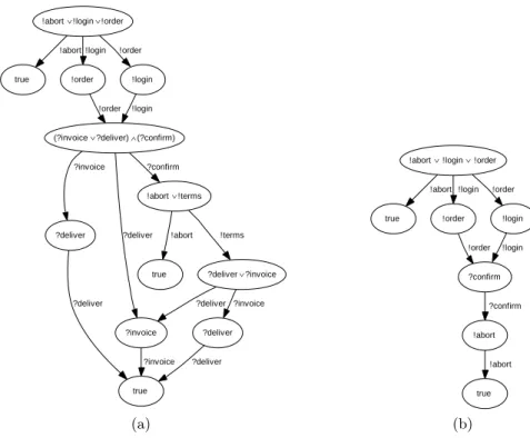
Figure 4 shows the operating guideline of the oWFNN1 depicted in Fig. 2.
In a node of the OG, the corresponding annotation is depicted. The reachable states ofN1are hidden.
!terms∨ !login∨ !order
!terms∨ !order !login
!terms∨ !login
!order
!login∨ !order
!terms
!terms∨ ?confirm
!order
!invoice∨ ?order
!terms
?invoice∨ ?confirm
!terms
!terms ?confirm
?confirm
?invoice
?invoice
?confirm
true
?confirm ?invoice
!terms
!order
!order
?invoice
!order
!login
!login
!terms
!login !login !order
Fig. 4. The OG for the oWFN N1 of Fig. 2. The annotation of the first node is a disjunction (!terms∨!login∨!order), i. e. a one-clause CNF formula. It means that every controller must, as its first event, send one of the three correspond- ing messages. The controller of Fig. 3, for instance, performs the event!loginwhich is obviously correct according to the OG.
The OG also allows a controller which first sends its order to N1. This possi- bility results from the proposed asyn- chronous way of interaction. Even if the order was sent first, it would keep pend- ing on the placeorderuntilN1 has con- sumed the login message sent later.
The annotation true of the last node means that no event has to be performed any more.
In sum, the OG of N1 characterizes 77 different controllers forN1.
3 Example Process: Online Shop
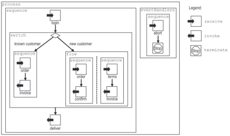
In this section we present an online shop as our example process. It is a simple but realistic business process and a modification of an online shop presented in [14]. The online shop’s BPEL specification consists of 15 activities and an
event handler and is depicted in Fig. 5. We abstract from the BPEL syntax and use a more intuitive graphical notation: a box frames an activity. For structured activities the corresponding BPEL construct is additionally depicted in the top left corner of the box. We use icons for basic activities, optionally with a mes- sage name shown below it. A sequence is depicted by arcs whereas concurrent activities are grouped in parallel separated by a dashed line.
new customer known customer
login
invoice order sequence
confirm order sequence
invoice terms sequence
deliver flow switch
sequence
abort sequence eventHandlers
Stop process
Legend:
Stop receive
invoke
terminate
Fig. 5.The online shop process.
When the online shop receives the login information from a customer, its business strategy distinguishes between already known customers and new cus- tomers. In case of a known customer the left branch is executed: first the shop expects an order, and then it sends the invoice to the customer. In case of a new customer (right branch) the shop initiates two tasks concurrently: in the first task (left sequence) the shop first receives the order and then confirms it. In the second task (right sequence) the shop receives the terms of payment before it sends an invoice to the customer. In either case the shop finally sends the delivery information to the customer. The customer may send an abort message at any time. We modeled this as an onMessage event handler that receives the abort message and then terminates the whole process. In Fig. 5 we depicted the event handler as a box, too. The expected message is also depicted by a receive icon.
4 Translating BPEL to Open Workflow Nets
4.1 Petri Net Semantics for BPEL
Our goal is to formally analyze BPEL processes. To achieve this goal we translate a BPEL process into an open workflow net using the semantics of [7]. As the
semantics itself is not the focus of this paper, we only summarize the main ideas of it. The semantics is guided by the syntax of BPEL. In BPEL, a process is built by plugging instances of BPEL constructs together. Accordingly, we translated each construct of the language separately into a Petri net. Such a net forms a pattern of the respective BPEL construct. Each pattern has an interface for joining it with other patterns as it is done with BPEL constructs. The semantics aims at representing all properties of each BPEL construct within its respective pattern.
Please note that a pattern itself is not an open workflow net. Only the com- position of all patterns of the activities of the process forms an open workflow net. The collection of patterns forms our Petri net semantics for BPEL. The semantics is complete (i. e. it covers all the standard and exceptional behavior of BPEL) and formal (meaning it is suitable for computer-aided verification).
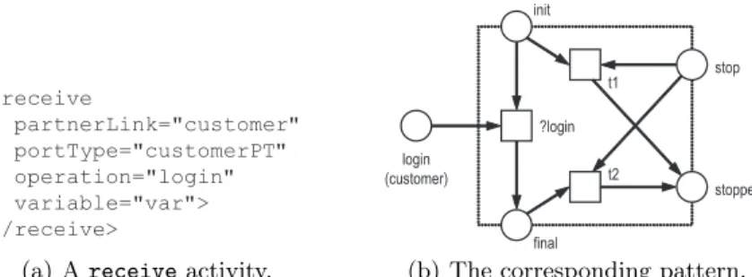
However, to decide controllability or to construct the operating guideline of a BPEL process it is not necessary to model all features of BPEL. As an example, Fig. 6(a) shows the receive activity “login” as it is used in the online shop.
Figure 6(b) shows its corresponding Petri net pattern that is used to check con- trollability in the following sections. It is an abstraction of the original pattern of the semantics and does neither model variables nor correlation sets. As a means of simplification, we also do not model the occurrence of BPEL standard faults in the whole process.
<receive
partnerLink="customer"
portType="customerPT"
operation="login"
variable="var">
</receive>
(a) Areceiveactivity.
init
final
?login
t2 t1
stop
stopped login
(customer)
(b) The corresponding pattern.
Fig. 6.The input placeloginis determined by the givenpartnerLink,portType, and operation. The dotted box frames the pattern. The places on the frame (init,final,stop, andstopped) describe the interface of the pattern used to join it with other patterns.
The execution of the activity can be stopped any time by marking placestopand firing eithert1ort2.
4.2 The Tool BPEL2oWFN
The described Petri net semantics for BPEL was prototypically implemented in the tool BPEL2PN [8]. The resulting Petri net does not model the interac- tional behavior and therefore only allows for verification of the internal behavior.
Another drawback of BPEL2PN is its “brute-force” mapping approach which re- sults in huge models for BPEL processes of realistic sizes and therefore does not permit efficient analysis.
To scale down the model size we pursue three objectives. (1) We improve the Petri net patterns of the semantics. (2) We choose specific (smaller) patterns from a repository with the help of information gained by static analysis. (3) We use structural simplification rules to compact the generated Petri net model and thus reduce its state space. These features were implemented in the tool BPEL2oWFN2, the successor of BPEL2PN. BPEL2oWFN is capable of gener- ating oWFNs and other file formats (PNML, low-level PEP notation, APNN, and LoLA low-level nets) and thus supports a variety of analysis tools.
Novel patterns. The Petri net semantics as described in [7] was designed to formalize BPEL rather than to automatically generate compact Petri net models that are necessary for computer-aided verification. Some patterns were designed to be easily understood and made use of quite “expensive” constructs such as reset arcs. We improved these patterns and replaced them by less intuitive patterns with simpler structure. As mentioned before, we abstract from data and model data-driven decisions by non-determinism. As a result, the generated oWFN is a 1-safe low-level Petri net which improves the verification performance.
Static analysis.Instead of mapping each BPEL activity to a single pattern modeling its behavior in all possible contexts, BPEL2oWFN employs a reposi- tory of several patterns for each activity. Each pattern (e. g. thereceivepattern in Fig. 6(b)) is designed for a certain context or to preserve specific properties only. To choose the most compact pattern for a certain verification task, we perform static analysis (see [15] for an overview) for the BPEL process.
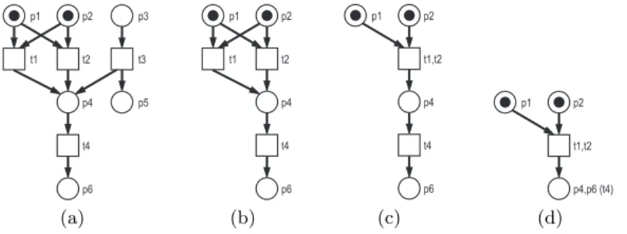
Structural simplification.Finally, we use structural reduction rules to further scale down the size of the generated Petri net model w. r. t. the requirements of the given analysis task. Currently, three reduction rules are implemented: at first, all structural dead places and transitions are removed. Secondly, duplicate transitions are merged. Thirdly, simple sequences (a transition with exactly one place in its preset and postset) are collapsed. As the nodes of the IG consist of sets of reachable markings, structural reduction may dramatically scale down the size of the IG. The rules are exemplified in Fig. 7.
4.3 Translating the Online Shop
Using BPEL2oWFN, we now translate the online shop example process into an oWFN3. The generated net originally has 112 places (including 4 input and 3 output places), 117 transitions, and 371 arcs. Structural reduction simplifies the net to 61 places (including the 4 input and 3 output places), 58 transitions, and 191 arcs. The structural reduction also affects the state space of the inner of the generated oWFN. The number of reachable states is reduced from 510 to 205.
2 available athttp://www.informatik.hu-berlin.de/top/tools4bpel/bpel2owfn
3 As the process terminates after receiving an abort message, we modeled the event handler to receive at most one abort message. Thus, the generated oWFN is acyclic.
t1 t2 t3 p3 p1
p4 p5
p2
t4
p6
(a)
t1 t2
p1
p4 p2
t4
p6
(b)
t1,t2 p1
p4 p2
t4
p6
(c)
t1,t2 p1
p4,p6 (t4) p2
(d)
Fig. 7. The implemented structural reduction rules. From the original net (a) all structural dead places and transitions are removed (b). Then duplicate transitions are merged (c), and simple sequences are collapsed (d).
5 Analyzing the Interaction of oWFNs
5.1 The Tool Fiona
Fiona4 is a tool to automatically analyze the interactional behavior of a given oWFN N. Fiona provides two techniques: it checks for the controllability of N, and it calculates the operating guideline for N. Fiona uses oWFNs as its input which is the output of BPEL2oWFN. Thus we can easily analyze BPEL processes.
Depending on the goal the user wants to achieve (controllability analysis or calculation of the operating guideline) the tool either builds up the interaction graph or the operating guideline. Fiona computes the nodes and the events of the respective graph as described in Sect. 2. To compute the states of the graph nodes we use efficient algorithms that were implemented in the model checking tool LoLA [16].
To find a controller in the computed graph (IG or OG), each of its nodes is analyzed. The analysis is done while the graph is constructed. It is a backward analysis starting at the leaf nodes. The analysis makes use of colors: black nodes are yet to be analyzed, blue nodes denote nodes of the controller and red nodes are not part of the controller. Initially, each node is colored black. If we have calculated a leaf node of the graph which contains only such deadlocks that are final markings, we color this node blue. If a leaf contains further deadlocks, it is colored red (since every such deadlock is not resolved). An internal node becomes blue if there exists for each deadlock (which is no final marking) an activated event leading to a blue node again. If this is not the case, the node becomes red. In case of building the OG, the analysis additionally computes the Boolean annotation of the node. Finally, each node has been colored either blue or red. The graph contains a controller iff the root node is blue. The controller is constituted by the largest connected blue subgraph that contains the root node.
4 available athttp://www.informatik.hu-berlin.de/top/tools4bpel/fiona
Fiona implements several optimizations: for instance, the red color of a node can sometimes be concluded before all of its successors are known. For such a node, we do not need to compute the remaining successors, since they cannot be part of the controller later on. Furthermore, not all states in a node must be stored to compute the successors – these states are rejected.
5.2 Analyzing the Online Shop Model
We now want to analyze our online shop example from Sect. 3. Firstly, we use Fiona to calculate the IG of the corresponding oWFN which we got from Sect. 4.3. The IG consists of 16 nodes and 19 edges. A blue subgraph can be found that has 8 nodes and 8 edges, containing the root node. Thus this subgraph constitutes a controller and the online shop is controllable.
The controller found reflects the intended behavior of a customer. First he sends a login, followed by an order. Then he must be able to either receive an invoice (in case he is known to the shop) or to receive the confirmation (in case he is a new customer). If he actually has received the confirmation, he must send a terms of payment message. After that he will receive the invoice. In either case he finally receives the delivery information. At any time he may abort. We did not depict the IG due to the lack of space and because it can be found as a subgraph in the corresponding OG. The latter has 12 nodes and 15 edges and is depicted in Fig. 9(a). Compared to the IG, the OG contains more interleavings of sending or receiving messages. For instance, a customer may reverse the order of sending the login and the order message.
6 The Online Shop Revised
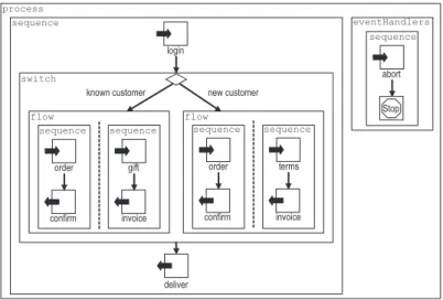
Let us take a look at the online shop presented in Sect. 3 once again. The shop now modifies its business strategy: every known customer that orders something can choose a gift. The modified online shop is depicted in Fig. 8.
The changes only affect the left branch of the switch. The shop initiates two tasks concurrently now: in the first task (left sequence) the shop first receives the order and then confirms it. In the second task (right sequence) the shop receives which gift is chosen before it sends the invoice to the customer. The rest of the process is as in Fig. 5.
The analysis with Fiona reflects that this simple change has a crucial effect on the behavior of the process. The IG of the revised online shop has 32 nodes and 40 edges. The corresponding controller inside the IG consists of 6 nodes and 5 edges which is less than the original controller of Sect. 5.2. Our algorithm concludes that the process is controllable, too. However, the reflected strategy is not the intended one. The controller in the IG represents a customer who sends an abort message during the interaction.
The IG represents only one customer’s behavior. For further information we need Fiona to calculate the OG. It is depicted in Fig. 9(b) and consists of 7 nodes and 7 edges. A closer look at the OG reveals that actuallyevery customer
new customer known customer
login
confirm order sequence
invoice terms sequence
deliver flow switch
sequence
abort sequence eventHandlers
Stop process
confirm order sequence
invoice gift sequence flow
Fig. 8.The modified online shop.
of the modified shop must eventually send an abort message. This surely means that the process is controllable. However, the way this is done is obviously a not intended one. There is no way that a customer can get what he has ordered from the process.
Let us take a look at what went wrong when we modified our online shop from Sect. 3. We can see that the shop does not communicate its inner decision about which branch (known customer, new customer) is chosen. In the original online shop (Fig. 5) the controller must send an order, but receives either an invoice or a confirmation w. r. t. which branch the shop has chosen before. That way the controller knows what branch the shop is actually in and hence knows how to continue. In contrast, in the modified shop the controller must send an order and receives undistinguishable confirmation messages in either case. The modified shop expects a choice of a gift in case it decided for the known customer branch.
In the other case it expects the terms of payment. The controller, however, does not know about the decision of the shop. That means, it does not know what message to send. This is reflected by the OG of the new shop as well (see Fig. 9(b)): in the situation where a partner receives the confirmation he does not know whether the shop decided for the left or the right branch. Hence, he can choose either to send a gift choice or the terms of payment. In either case it is not guaranteed that the message will always be consumed, and therefore it should not be sent in the first place. However, sending an abort is always correct.
This simple example shows that even a small modification of a process may result in an unintended interactional behavior. The effect on the interactional behavior of a BPEL process is not obvious. Since this is not obvious even for small processes as in our shop example, it is even more challenging for BPEL processes of realistic size. In general, processes may have a complex structure that it is not possible to detect such erroneous structures in the BPEL process
!abort∨!login∨!order
true
!abort
!order !login
!login !order
true (?invoice∨?deliver)∧(?confirm)
!order
?invoice
?deliver
?deliver
?invoice
!abort∨!terms
?confirm
true ?invoice
?deliver
?deliver
?deliver∨?invoice
?deliver ?invoice
?deliver
!abort !terms !login
(a)
!abort∨ !login∨ !order
true
!abort
!order !login
!login !order
?confirm !order
!abort ?confirm
true !abort
!login
(b)
Fig. 9. Operating guidelines (a) of the original online shop of Fig. 5 and (b) of the modified shop of Fig. 8. The OG in (a) characterizes different intended customers of the original shop, whereas the OG in (b) documents that there is only one possible way to interact with the modified shop: to abort.
manually. With the help of the operating guideline we can see if there exists a controller that interacts with our process as we have expected it during the process design.
7 Related Work
Several groups have proposed formal semantics for BPEL. Among them, there are semantics based on finite state machines [17, 18], the process algebra Lo- tos [19], abstract state machines [20, 21], and Petri nets [22, 7]. The group of van der Aalst also follows a Petri net-based approach [22]. Their semantics, however, does not cover the communication of BPEL. It enables several analysis meth- ods including the detection of unreachable activities and BPEL standard faults like “conflicting receive” (two concurrent receive activities are waiting for the same input message). Further, it is possible to perform a reachability analysis for the garbage collection of unconsumable messages later on. Those methods are implemented in the tool WofBPEL [23].
In [24] BPEL processes are transformed into an annotated subset of oWFNs, BPEL annotated Petri nets (BPNs). The transformation is oriented on a mod- ified version of our semantics [7], which does not include most of the fault and compensation handling. For BPNs a technique for analyzing the controllability has already been introduced in [14] – the communication graph. It is similar to our proposed IG. As a main difference, this graph performs communication steps, where each step consists of a (possibly empty) sending phase followed by a (possibly empty) receiving phase. Therefore, the communication graph tends to be more complex than our IG (cf. [4]).
8 Conclusion and Further Work
We presented a framework to formally analyze the interactional behavior of BPEL processes. Both the translation from BPEL into compact Petri net models as well as the further analysis of controllability and the computation of the operating guideline are implemented which allows for a fully-automatic analysis.
The results show that we can detect non-trivial model flaws of interacting BPEL processes that would have been hard or impossible to find manually.
In the current translation approach we use static analysis to compact the generated model only. However, it is possible to check certain properties stat- ically, i. e. without generating a model at all. In future work we want to use control flow analysis to detect unreachable (thus dead) activities or other design flaws. To further support this analysis, we have to add data aspects to our model and replace non-determinism by data-driven decisions.
To analyze interactions consisting of more than two interacting processes, existing theoretical results have to be integrated into Fiona. In addition, algo- rithms to decide controllability and to compute the operating guidelines of cyclic oWFNs have to be established to complete the analysis spectrum.
To support the redesign of erroneous (e. g. not controllable) services, the analysis results (e. g. counter-examples) have to be translated back into BPEL source code. This will be extremely helpful to support process designers during the modelling.
Finally, our tool Fiona is not restricted to analyze BPEL processes only. Since Fiona uses oWFNs as its input we have a very general formalism at hand that can be used to model various kinds of interacting processes. Therefore Fiona can, for instance, also be used to analyze interorganizational workflow as well.
References
1. Hull, R., Benedikt, M., Christophides, V., Su, J.: E-Services: A Look Behind the Curtain. In: PODS ’03, New York, USA, ACM Press (2003) 1–14
2. Papazoglou, M.P.: Agent-Oriented Technology in Support of E-Business. Commu- nications of the ACM44(4) (2001) 71–77
3. Andrews, T., et al.: Business Process Execution Language for Web Services, Ver- sion 1.1. Technical report, BEA, IBM, Microsoft (2003)
4. Weinberg, D.: Reduction Rules for Interaction Graphs. Technical Report 198, Humboldt-Universit¨at zu Berlin (2006)
5. Massuthe, P., Schmidt, K.: Operating Guidelines – An Automata-Theoretic Foun- dation for Service-Oriented Architectures. In: QSIC 2005, Melbourne, Australia, IEEE Computer Society (2005) 452–457
6. Massuthe, P., Reisig, W., Schmidt, K.: An Operating Guideline Approach to the SOA. AMCT1(3) (2005) 35–43 To appear.
7. Stahl, C.: A Petri Net Semantics for BPEL. Techn. Report 188, Humboldt- Universit¨at zu Berlin (2005)
8. Hinz, S., Schmidt, K., Stahl, C.: Transforming BPEL to Petri Nets. In: BPM 2005.
Volume 3649 of LNCS., Nancy, France, Springer-Verlag (2005) 220–235
9. Schmidt, K.: Controllability of Open Workflow Nets. In: EMISA. LNI, Bonner K¨ollen Verlag (2005) 236–249
10. Aalst, W.: The Application of Petri Nets to Workflow Management. Journal of Circuits, Systems and Computers8(1) (1998) 21–66
11. Ramadge, P., Wonham, W.: Supervisory Control of a Class of Discrete Event Processes. SIAM J. Control and Optimization25(1) (1987) 206–230
12. Badouel, E., Darondeau, P.: Theory of Regions. In: Lectures on Petri Nets I: Basic Models. Volume 1491 of Lecture Notes in Computer Science. (1998) 529–586 13. Massuthe, P., Schmidt, K.: Operating Guidelines – An Automata-Theoretic Foun-
dation for Service-Oriented Architectures. to appear (2006)
14. Martens, A.: Verteilte Gesch¨aftsprozesse – Modellierung und Verifikation mit Hilfe von Web Services. PhD thesis, Humboldt-Universit¨at zu Berlin (2004)
15. Nielson, F., Nielson, H.R., Hankin, C.: Principles of Program Analysis. 2nd edn.
Springer-Verlag (2005)
16. Schmidt, K.: LoLA: A Low Level Analyser. In: ICATPN 2000. Number 1825 in LNCS, Springer-Verlag (2000) 465–474
17. Arias-Fisteus, J., Fern´andez, L.S., Kloos, C.D.: Formal Verification of BPEL4WS Business Collaborations. In: EC-Web’04. Volume 3182 of LNCS., Springer (2004) 76–85
18. Fu, X., Bultan, T., Su, J.: Analysis of Interacting BPEL Web Services. In:
WWW ’04, ACM Press (2004) 621–630
19. Ferrara, A.: Web Services: A Process Algebra Approach. In: ICSOC, ACM (2004) 242–251
20. Fahland, D., Reisig, W.: ASM-based Semantics for BPEL: The Negative Control Flow. In: ASM’05, Paris XII (2005) 131–151
21. Farahbod, R., Gl¨asser, U., Vajihollahi, M.: Specification and Validation of the Business Process Execution Language for Web Services. In: ASM. Volume 3052 of LNCS., Springer (2004) 78–94
22. Ouyang, C., Verbeek, E., van der Aalst, W.M., Breutel, S., Dumas, M., ter Hofst- ede, A.H.: Formal Semantics and Analysis of Control Flow in WS-BPEL. Technical report (revised version), Queensland University of Technology (2005)
23. Ouyang, C., Verbeek, E., Aalst, W., Breutel, S., Dumas, M., ter Hofstede, A.:
WofBPEL: A Tool for Automated Analysis of BPEL Processes. In: ICSOC 2005.
Volume 3826 of LNCS., Amsterdam, The Netherlands (2005) 484–489
24. Martens, A., Moser, S., Gerhardt, A., Funk, K.: Analyzing Compatibility of BPEL Processes – Towards a Business Process Analysis Framework in IBM’s Business Integration Tools. In: ICIW’06, IEEE Computer Society Press (2006)

![Fig. 3. The IG for the net N 1 of Fig. 2. The first node of the IG represents the hypothesis that the controller of N 1 has about N 1 when neither messages have been sent nor received: the net must be in state [p0], which is a deadlock](https://thumb-eu.123doks.com/thumbv2/1library_info/5601070.1691077/6.918.517.719.170.556/fig-represents-hypothesis-controller-messages-received-state-deadlock.webp)