on Functional Safety for
Industrie 4.0 and Intelligent Manufacturing
bmwi.de
Imprint
Published by
Federal Ministry for Economic Affairs and Energy Public Relations Division
11019 Berlin www.bmwi.de Design
Iris Christmann, Wiesbaden Status
July 2020
This brochure is published as part of the public relations work of the Federal Ministry for Economic Affairs and Energy. It is distributed free of charge and is not intended for sale. The distribution of this brochure at campaign events or at information stands run by political parties is prohibited, and political party-related information or advertising shall not be inserted in, printed on, or affixed to this publication.
Text
Standardization Council Industrie 4.0 DKE Deutsche Kommission Elektrotechnik Elektronik Informationstechnik in DIN und VDE, 60596 Frankfurt am Main
National Intelligent Manufacturing Standardisation Administration Group
China Electronics Standardization Institute,
No.1 Andingmen East Street, Dongcheng District, Beijing, 100007, China
Authors/Experts
Pan Dongbo, Southwest University; Feng Dongqin, Zhejiang Univer- sity; Silvio Förtsch, Siemens AG; Andreas Hildebrandt, Pepperl + Fuchs EG; Holger Laible, Siemens AG; Jochen Link, ING-Link; Zouqing Meng, Instrumentation Technology and Economy Institute (ITEI); Kun Qiu, Zhejiang Supcon Technology Co., Ltd.; Xueling Shi, Instrumentation Technology and Economy Institute (ITEI); Peter Sieber, HIMA Paul Hildebrandt GmbH; Karl Waedt, Framatome GmbH; Wenze Xiong, Ins- trumentation Technology and Economy Institute (ITEI); Jie Zhu, Zheji- ang Supcon Technology Co., Ltd.; Xin Zuo , China Techenergy Co.,Ltd List of Stakeholders
Standardization Council Industrie 4.0: The Standardization Council Industrie 4.0 (SCI 4.0) was founded at the Hannover Messe 2016 as a German standardization hub by Bitkom, DIN, DKE, VDMA and ZVEI.
The initiative aims to initiate standards for digital production and to coordinate these standards nationally and internationally. SCI4.0 or- chestrates the implementation of the standardization strategy of the German Plattform Industrie 4.0, which includes the coordination with standardization organizations (SDO) and international partners as well as the interlocking with Pilot projects. This coordinated approach will achieve that the norms and standards for the use of potentials of In- dustrie 4.0 are being developed in a coordinated manner. The SCI4.0 is supported by DKE and the German Federal Ministry for Economic Affairs and Energy (BMWi).
Plattform Industrie 4.0: Plattform Industrie 4.0 promotes the develop- ment of Industrie 4.0 in Germany. Companies, their workforce, trade unions, associations, science and politics have joined forces in the plat- form to promote the digital transformation of manufacturing in Ger- many and to strengthen the competitiveness of Germany as a produc- tion location. The platform is steered and led by the federal minister for economic affairs and energy, Peter Altmaier, the federal minister of education and research, Anja Karliczek, and high-ranking representati- ves from industry, science and the trade unions.
Intelligent Manufacturing Standardization Administration Group:
The Intelligent Manufacturing Standardisation Administration Group (IMSG) was established to promote and accelerate the progress of intel- ligent manufacturing in China under the leadership of Standardization Administration of China (SAC) and Ministry of Industry and Informa- tion Technology (MIIT). It is responsible for carrying out the practical work on Intelligent manufacturing standardisation, such as taking part in the international standard-making on intelligent manufacturing as well as organizing the exchange and cooperation on international standards.
Global Project Quality Infrastructure: To promote the development of well-functioning and internationally coherent quality infrastructures, the German Federal Ministry for Economic Affairs and Energy (BMWi) has established the Global Project Quality Infrastructure (GPQI). GPQI supports the political and technical dialogues and implements bilate- rally agreed activities in collaboration with all relevant stakeholders.
The project aims to reduce technical barriers to trade and enhance product safety through bilateral political and technical dialogues on QI with some of Germany’s key trading partners.
0 Introduction 5
0.1 Background and context 5
0.2 Compatibility with other Sino-German guidance 5
0.3 Related standardization committees 5
1 Scope 6
2 References to related standards and guidelines 6
3 Terms, definitions and abbreviations 6
4 History of safety in industry 7
4.1 Safety accidents 7
4.2 Safety-related legal requirements 7
4.3 Different safety domains 8
5 Current approaches to safety in industry 9
5.1 Risk reduction strategy for ensuring safety 9
5.2 Triggering of hazardous events 9
6 Introduction to Industrie 4.0 and IM 10
7 I4.0 and IM challenges and new risks to safety 11
7.1 Risks due to new technology 11
7.2 Creating a link between I4.0 and IM and Functional Safety 12
7.2.1 I4.0 and IM concept (axis 3 of RAMI) 12
7.2.2 Solution 14
7.2.3 Protection of the I4.0 and IM workspace and safety-related installations 14
7.2.4 Functional Safety for I4.0 and IM 15
7.3 Zones & conduits 15
7.4 Considerations for safe and secure communication 15
7.5 Risks due to system complexity and interconnectivity 18
7.6 Risks due to system interoperability 18
7.7 Risks due to lack of maturity of intelligent technologies and products 19
CONTENTS
8 Safety in the context of security 19
8.1 Preconditions to be met by the security framework 19
8.1.1 Domain-specific knowledge 20
8.1.2 Security grading 20
8.1.3 Security requirements 20
8.2 Preconditions to be met by the functional safety framework 21
8.2.1 Domain-specific knowledge 21
8.2.2 Functional safety grading (extract from IEC 61508) 21
8.2.3 Functional safety requirements 21
8.3 Challenges of achieving safety while also considering security 22
8.3.1 Overview 22
8.3.2 Security from the perspective of safety 22
8.3.3 Safety from the perspective of security 22
8.4 Gaps in current standards and guidance 23
8.5 Safety management with consideration of security 24
8.6 Lifecycle with consideration of safety and security 24
8.6.1 General information 24
8.6.2 Risk assessment 25
8.6.3 System implementation 25
8.6.4 Engineering and systems integration 26
8.6.5 Operation and maintenance 26
Bibliography 28
0 Introduction
0.1 Background and context
Conventional Industrial Automation Control Systems (hereinafter: IACS) are based solely on mechanical and elec- tronic technology. Different devices or systems are isolated or have limited connectivity. Typically, it is common to use functional safety measures to deal with safety issues, which are mainly based on the general functional safety standard IEC 61508 and domains-specific standards, e.g. IEC 61511 for the process industry, IEC 62061 or ISO 13849 for the machinery sector and ISO 26262/ISO 21448 for the auto- motive industry.
However, with the rise of Industrie 4.0 and Intelligent Man- ufacturing (hereinafter: I4.0 and IM), more and more intelli- gent and digital technology is required for IACS. To meet this need, an increasing number of information technolo- gies, communication devices and smart devices are being integrated into modern control systems. This increases the degree of complexity and interconnection among systems.
Although this can increase efficiency and reduce costs for industries, the overall infrastructure will become more susceptible to internal failures and more vulnerable to cy- berattacks.
All of these new issues – including new hazards, e.g. security related attacks – therefore need to be considered to ensure that I4.0 and IM remain safe. Existing international stand- ards need to be interpreted and amended to cover these is- sues. This paper surveys and analyses existing standards, specifications and research to give an overview of safety for I4.0 and IM.
0.2 Compatibility with other Sino-German guidance
This White Paper on Functional Safety is one of the research outcomes on I4.0 and IM under a programme by the Sino- German Standardization Cooperation Commission. It is compatible with other publications in the Sino-German programme, such as ‘Security Standards White Paper for Sino-German Industrie 4.0/Intelligent Manufacturing’,
‘Alignment Report for Reference Architectural Model for Industrie 4.0/Intelligent Manufacturing System Architec- ture’ etc.
0.3 Related standardization committees
Working group IEC/TC65/WG20 with the title ‘Framework for safety and security’ was specifically created within IEC/
TC65 ‘Industrial-process measurement, control and auto- mation’ to jointly address both the safety and security re- quirements. Some results of this White Paper on Functional Safety may later be integrated into working documents of IEC/TC65/ WG20.
DKE working group TBINK-AK IT-Security and Security by Design, (hereinafter: TBINK-AK IT-Security) is currently focusing on rendering multipart-guidance on joint consid- erations of functional safety and cybersecurity.
Note: In the elaboration of this White Paper on Functional Safety, Germany’s DKE/AK 914.0.6 has partnered with its Chinese counterpart the Instrumentation Technology and Economy Institute (hereinafter: ITEI).
SAC/TC124 is the Chinese Committee on Functional Safety and Industry Security, which has released many Chinese standards about functional safety, industrial security and the integration of safety and security.
1 Scope
This White Paper is used to research the safety issues in the I4.0 and IM application environment. It will explain the ba- sic concept of conventional technical safety and consider the evolution of I4.0 and IM and its implications for safety techniques. Security will become a very important factor for I4.0 and IM safety. This White Paper will also discuss the potential integration of safety and security.
2 References to related standards and guidelines
IEC 61508 Functional safety of electrical/electronic/
programmable electronic safety-related systems – Parts 1 to 7
IEC 61511 Functional safety - Safety instrumented systems for the process industry sector – ALL PARTS
IEC 62443 All parts, industrial communication networks – Network and system security
IEC TR 63069 – Industrial-process measurement, control and automation – Framework for functional safety and security
ISO/IEC 27021 Information technology – Security techniques – Competence requirements for information security management systems professionals
ISO/IEC 27034-2 Information technology – Security tech- niques – Application security – Part 2: Organization norma- tive framework
ISO 12100 Safety of machinery – General principles for design – Risk assessment and risk reduction
IEC 62061 Safety of machinery – Functional safety of safe- ty-related electrical, electronic and programmable elec- tronic control systems
ISO 13849 – 1 Safety of machinery – Safety-related parts of control systems – Part 1: General principles for design ISO 13849 – 2 Safety of machinery – Safety-related parts of control systems – Part 2: Validation.
ISO 26262 All parts, Road vehicles – Functional safety
3 Terms, Definitions and Abbreviations
Please refer to IEC 61508-4, IEC 62443-1-1 and IEC TR 63069 for the terms, definitions and abbreviations.
4 History of safety in industry
4.1 Safety accidents
What are accidents?
Accidents are unplanned and unintentional events that result in harm to humans, damage to the environment (safety incidents) or property, production outages, or nearly anything that has some inherent value (economic targets).
These losses increase an organisation’s operating costs because they raise production costs, reduce efficiency, and lead to lower employee morale and negative public opinion long term. Accidents are rarely simple and hardly ever re- sult from a single cause. Most accidents involve multiple, interrelated causal factors. Accidents can occur whenever significant deficiencies, oversights, errors, omissions, or un- anticipated changes are present. Any of these conditions can be a precursor for an accident; the only uncertainties are when the accident will occur and how severe its consequences will be.
How about protection?
Safety risk management prevents or mitigates accidents by identifying and implementing the appropriate controls and barriers. Controls help to prevent errors or failures that could result in an accident; barriers help to mitigate the consequences of potential errors or failures. Barriers to pro- tect targets against loss can be physical barriers, such as ma- chine guards and railings, or management barriers, such as work procedures, hazard analysis, requirements manage- ment, line management oversight, and communications. In a work environment, several barriers may be used in an ef- fort to prevent accidents. Accidents occur when one or more barriers in a work system, including procedures, standards, and requirements intended to control the actions of workers, fail to perform as intended. The barriers may not exist, may not be adhered to, or simply may not be com- prehensive enough to be effective. Personal performance and environmental factors may also reduce protection.
Accidents in industry
With the rapid development of industry, potential safety accidents are continuing to emerge. Although people have adopted various protection measures, safety accidents are still occurring. The Seveso II Directive Major Accident Reporting System (hereinafter: MARS) holds data on ap- proximately 600 major accidents that have been notified since 1984, with approximately 30 notifiable accidents being reported on an annual basis since 2000.
4.2 Safety-related legal requirements
The European Commission (hereinafter: EC) has introduced a number of directives on health and safety matters. Some of these lay down minimum requirements, which are in- tended to form the basis of harmonised workplace health and safety laws throughout the Member States of the EU.
New regulations have been introduced in the UK to imple- ment these directives, including:
•
The Management of Health and Safety at Work Regulations 1999•
The Provision and use of Work Equipment Regulations 1998 and•
The Health and Safety (Display Screen Equipment) Regulations 1992Other EC directives, sometimes referred to as New Ap- proach Directives, aim to remove barriers to trade that may arise from different design and manufacturing stand- ards among Member States. The most significant of these is the Machinery Directive, which the Department of Trade and Industry has implemented in the UK as the Supply of Machinery (Safety) Regulations 1992 (as amended in 1994).
The basic legislative framework in the European Union is as follows:
•
EU directive (European law), e.g. Seveso Directive, Machinery Directive, Pressure Equipment Directive, Low Voltage Directive, EMC Directive etc.•
Definition of underlying standards (harmonised stand- ards attached to EU directive), e.g. for machinery ISO 12100, IEC 62061, EN/ISO 13849, etc.•
Local implementation, e.g. in Germany the Safety at Work Act (Arbeitssicherheitsgesetz), Hazardous Incident Ordinance (Störfallverordnung).•
Local implementation rules, e.g. in Germany VDI/VDE 2180 as the implementation rule for IEC 61511.In China, production and manufacturing safety is the respon- sibility of the Ministry of Emergency Management of the eople‘s Republic of China. Its responsibilities also include:
•
Organising the preparation of overall national emer- gency plans•
Establishing a disaster reporting system and dealing with the disaster situation•
Guiding the prevention and control of fires, floods and droughts, geological disasters, etc.•
Undertaking comprehensive supervision and manage- ment of safety production and safety production super- vision and management of industrial and mining safetyThe State Administration for Market Regulation is responsi- ble for product safety, safety inspection/tests and safety approval, including responsibility for
•
product quality and safety supervision and management•
food safety supervision and management•
unified management of standardisation•
unified management of inspection and tests The basic legislative framework in China is as follows:•
National law, e.g. People’s Republic of China Safety Production Law, People‘s Republic of China Mine Safety Law, etc.•
Regulations or national orders, e.g. Hazardous Chemicals Safety Management Regulations, Safety Production License Regulation, State Council Order No. 639: Railway Safety Management Regulations, etc.•
Ministry order, Ministry of Emergency Management of the People‘s Republic of China (No. 1) on safety evalua- tion testing and inspection agency Management, etc.•
Standards, including mandatory standards and recom- mended standards, GB/T 20438-2017 (IEC61508 idt), GB/T 21109-2007 (IEC 61511 idt), GB 18218-2018, identi- fication of major hazard installations for hazardous chemicals•
Local implementation, e.g. for coal mines, oil and gas, transportation and in other areas4.3 Different safety domains
Safety has a very wide meaning for different applications in industry. As a result of the last three industrial revolutions, the issue of safety is also constantly evolving.
Mechanical safety Example:
•
To protect a vessel against overpressure•
A well-known mechanical safety measure is to attach a safety valve to such a vessel. For this application, a spring is used to keep the valve closed. In the event that the pressure inside the vessel exceeds a predefined limit, the valve opens and the pressure is released.•
It has to be ensured that the valve is directly attached to the pressurised vessel. If the valve is connected via a piece of pipe only, the desired safety measure will not work correctly.•
The correct function of the valve is to be tested at regular intervals. Depending on the size of the valve (mechanical dimensions, rated pressure), the location of the valve (e.g. at the bottom of the sea), it might be challenging to perform such testing.Electrical safety Example:
•
To protect users from electrical shock•
To protect users from electrical shock in the event of an iso- lation fault, all conductive elements of a housing are gal- vanically connected to protective earthWhen designing an electrical supply system, a protective earth conductor of sufficient dimension has to be installed so that every electrical device can be connected to such a conductor.
In order to guarantee correct functioning, the functional- ity of such a protection conductor system might need to be checked at regular intervals. Due to the amount of connections (every outlet socket) and the amount of de- vices (every cord connected device), this can be a signifi- cant undertaking.
Functional safety:
Example:
•
Reduce the probability of the occurrence of a hazardous event•
In order to prevent the unwanted occurrence of a hazard- ous event (e.g. overheating of a vessel), a functionality is implemented that stops a process (e.g. supply of heat to a vessel) in the event that pre-defined limits (e.g. the maxi- mum temperature of such a vessel) are violatedThere are 2 design challenges:
1. To properly define all conditions that will cause the safety functions to be activated
2. To define all conditions that may hinder the safety function from functioning once triggered
There are 2 maintenance challenges:
1. To ensure that the correct function can be guaranteed 2. To make sure that no modifications are made that n
egatively impair the safety function throughout its en- tire lifetime
5 Current approaches to safety in industry
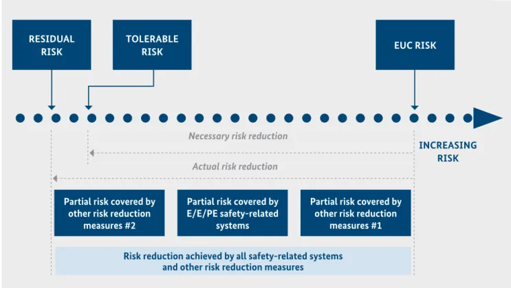
5.1 Risk reduction strategy for ensuring safety
Risk management and risk reduction are commonly ac- cepted processes for maximising safety. These processes seek to reduce risk using different protection measures to achieve tolerable risk targets.
The necessary risk reduction is the reduction in risk that has to be achieved to meet the tolerable risk targets for a specific situation (which may be stated either qualitatively or quantitatively). The notion of necessary risk reduction is of fundamental importance in the development of the safety requirements specification for the E/E/PE safety related systems. In particular, this concerns the Safety Integrity Level (SIL or Performance Level (hereinafter: PL)) part of the safety requirements specification. The purpose of determining the tolerable risk for a specific hazardous event is to state what is deemed reasonable with respect to both the frequency (or probability) of the hazardous event and its specific consequences. Safety-related systems are de- signed to reduce the frequency (or probability) of the haz- ardous event and/or the consequences of the hazardous event [IEC61508-5].
5.2 Triggering of hazardous events
Industrial accidents and disasters are caused by a chain of faults causing errors and resulting in failures. The thinking behind traditional safety strategies is to prevent hazards by designing systems which are fail-safe. This can be done through redundancy or the use of technical measures for safety critical technical components (e.g. separation, diver- sity, oversizing) according to IEC 61508 for safety systems (see chapter 5.1). Additionally, hazards resulting in accidents can be prevented by organisational measures.
By means of interconnected systems, hazardous events can also be influenced by security attacks and not only by tech- nical failures related to the system design. To prevent at- tacks, we have to understand the systems and manage their complexity (see chapter 7). To detect security vulnerabilities, risk assessments have to be done (see chapter 8.1) and tech- nical and organisational measures have to be in place. The method of implementing different barriers for security is called Defence in Depth (including technical and organisa- tional measures). The challenge to protect a critical safety system with completely interconnected systems is very high and safety cannot be guaranteed under all circum- stances (as there is also no 100% safe system).
Figure 1: Risk reduction concept for low demand operation mode (from IEC61508-5)
RESIDUAL RISK
TOLERABLE
RISK EUC RISK
INCREASING RISK Necessary risk reduction
Actual risk reduction
Partial risk covered by other risk reduction
measures #2
Partial risk covered by E/E/PE safety-related
systems
Partial risk covered by other risk reduction
measures #1 Risk reduction achieved by all safety-related systems
and other risk reduction measures
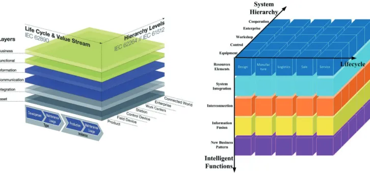
The 4th industrial revolution has arrived in the industrial sector. It is characterised by the increasing digitisation and interconnection of production, systems, value chains and business models. The Chinese and German governments have each published respective Reference Architecture Models (Germany: RAMI and China: IMSA). The alignment of both models was agreed upon (see the White Paper enti- tled ‘Alignment Report for Reference Architectural Model for Industrie 4.0/Intelligent Manufacturing System Archi- tecture’).
Figure 2: RAMI vs. IMSA
As shown in the figure, the RAMI 4.0 model maps the whole lifecycle and working scope of an industrial product or ser- vice along three axes. In the hierarchy axis, a smart factory can be abstracted as a pyramid model in which the enter- prise stays on the top and is refined down to the control de- vice level, the field device level and so on. The architecture axis represents different views of the product or service, such as the business view, the functional view, the commu- nication view and the asset view. The production lifecycle axis covers the full lifecycle of a product/service while tak- ing all participants such as supplier and integrator into ac- count. RAMI 4.0 provides a standard framework for track- ing details of a product or a service. For example, a safety function in the hierarchy axis can be mapped to relevant devices. In the architecture axis, the function is described in detail in the functional layer. To achieve the required safety goal, different production phases might be involved, e.g. the material quality needs to be defined in the design phase
while being guaranteed in the purchase phase.
However, considering security requirements within the RAMI or IMSA model is even more complex. Firstly, the compromising target may not be the described product or service directly but only be a feature of it (e.g. availability/
integrity or just an involved control device in the hierarchy axis). Secondly, a comprehensive attack can be achieved within the whole scope of the RAMI model. It may start from a lower hierarchy level to compromise a higher-level target (e.g. a factory station). In the architecture axis, it
comes with its own business purposes, compromises important functions as well as goes through a specific com- munication topology. At last, the attack can be deployed in the beginning of the lifecycle and will be only triggered at a given point, as part of an Advanced Persistent Threat (APT).
Accordingly, the security analysis should not be limited within a single level, layer of phase of the RAMI model, which means the search space is significantly increased.
However, for a given attack, the RAMI or IMSA model pro- vides a break-down view to analyse, discover and prevent or mitigate the attack with the knowledge of the product/
service.
6 Introduction to Industrie 4.0 and IM
7.1 Risks due to new technology
of functional safety, there is a wide range of challenges to be mastered. In this chapter, key aspects are highlighted and rec- ommendations made for further evaluations.
In general, there is a potential conflict between I4.0 and IM applications and the conventional way of implementing functional safety solutions.
Conventional solutions for functional safety are imple- mented with a static scenario in mind, while the basic idea of 4.0 applications is a seamless integration with more dynamic changes among the elements making up an overall business application, not limited to automation solutions only but also covering business applications. It needs to be kept in mind that solutions for functional safety are implemented in order to bring the risk on a dedicated application down to an acceptable level.
This objective has top priority for all applications of func- tional safety and shall not be influenced by either the tech- nology used or the individual application.
When thinking about functional safety and I4.0 and IM, the key factor is to make sure that the safety integrity required for attaining the anticipated risk reduction is achieved (see Figure 1 and description in Chapter 5).
This needs to be maintained during the entire lifecycle dur- ing all phases of operations, including patching and all other sorts of modification. That said, it needs to be kept in mind that for applications with very low safety requirements, the commercial benefits of an I4.0 and IM applications may pre- vail over safety considerations.
This, however, has to be looked at critically because even low- level safety solutions may cause hazards and legal implica- tions when such a function does not work correctly.
A solution designated to realise a dedicated SIL recommen- dation has to be able to comply with the related safety rec- ommendations irrespective of whether it is realised via hard-wiring, programmable, isolated or integrated into an I4.0 and IM environment.
Nevertheless, this does not mean that integrating solutions of functional safety into an I 4.0 and IM environment is not possible. However, the desired risk reduction capability needs to be maintained under all relevant aspects.
However, the interaction between safety and security, and their different requirements and types of implementation, are much more diverse. To take account of this fact, the IEC has set up a working group under the Technical Committee TC65 which has taken on the task of defining a framework for safety and security (project IEC TR 63069 Ed1). Within this framework, recommendations are given that arise from the interaction of these two complex topics.
In order to develop this framework and provide recommen- dations, a dedicated risk analysis is needed so that new risks can be identified, and both safety and security aspects are con- sidered in an adequate manner (see IEC TR 63069).
According to the rules applicable for the implementation of functional safety, the following main areas are to be looked at:
•
The capabilities of the products to be used•
The design processes at application level•
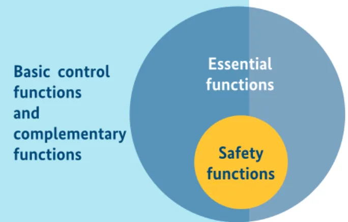
The lifecycle support activities incl. testing and mainte- nance activities with a special focus on updating/ up- grading processesTaking account of the applicable security standards (IEC 62443), the plan is to develop an overall concept under which different security recommendations are required in order to trigger action (zones and conduits) at different functional lev- els of an application. Safety functions are “essential functions”
as per IEC 62443 and as such require particular attention (see below figure 3).
Figure 3: Correlation between different functional layers as per IEC 62443 (from IEC 63069)
In this document, the various situations that are encountered today are considered and a description of methods will be given on how functional safety can be realised and maintained in an I4.0 and IM workspace and protected against security threats through the implementation of security standards.
Basic control functions and
complementary
functions Safety
functions Essential functions
7 I4.0 and IM challenges and new risks to
safety
7.2.1 I4.0 and IM concept (axis 3 of RAMI)
When it comes to standard control devices and devices provid- ing functional safety, the difference is as follows: for functional safety devices, additional attributes are defined.
These are:
•
Dedicated reliability recommendations (low probability of failures or sufficient fault tolerance)•
Modes of operations (low demand mode or high/contin- uous demand mode)•
Systematic capability, leading to dedicated recommenda- tions for design, software and usage of a deviceFigure 4: Axis 3 of RAMI
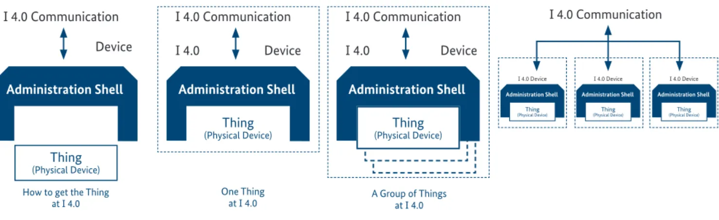
Figure 5: Integrating things in I4.0
Anticipating that functional safety in general is a kind of an at- tribute of physical devices (or the way such devices are used), we have to look at axis 3 of RAMI, the dimension in which the physical layering of I4.0 and IM applications is described.
A given device is connected to an administration shell that is handling functions required to establish the functions of the
‘digital twin’. The administration shell may be part of every device or may be hosted by a dedicated piece of equipment handling the digital twins of one or multiple devices.
This administration shell covers all functions required to inte- grate devices into an I4.0 and IM application. Such a shell may cover either a single physical device (e.g. a sensor), a functional group of devices (e.g. a PLC including its field devices) or a complete production unit (e.g. a machine or a process unit).
4
VIRTUAL SPACE
PHYSICAL SPACE
Business Processes
Generic functions, attributable to one or multiple devices Standardized Data Models Physical Communication
Hosting the Digital Twin Device
Business Processes Functions Information Communication
Digitalization Physical device(S)
R eal Digital W orld
I 4.0 Communication Device
Administration Shell
Thing
(Physical Device) How to get the Thing
at I 4.0
I 4.0 Communication I 4.0 Device
Thing
(Physical Device)
Administration Shell
One Thing at I 4.0
I 4.0 Communication I 4.0 Device
Administration Shell
A Group of Things at I 4.0
Thing
(Physical Device)
Looking at possible ways to integrate things (physical devices) in I4.0 and IM, the following can be anticipated:
7.2 Creating a link between I4.0 and IM and Functional Safety
i
I 4.0 Communication
I 4.0 Device I 4.0 Device I 4.0 Device
Thing (Physical Device) Administration Shell
Thing (Physical Device) Administration Shell
Thing (Physical Device) Administration Shell
SAFETY DEVICE Device Information
Physical Behavior (e.g. PFD, PFH, SFF, HFT)
Systematic behavior (e.g. systematic capabilities)
Plus Device Information SAFETY DEVICE Device Information
Physical Behavior (e.g. PFD, PFH, SFF, HFT)
Systematic behavior (e.g. systematic capabilities)
Figure 7: I4.0 Device
As described above, an I4.0 and IM com- ponent in the con- text of this docu- ment is either a de- vice or a station.
Each device/station is either equipped with an administra- tion shell. Such an administration shell can either be used to handle an individual component or, alternatively, multiple components can be hosted in the same shell.
Figure 8: I4.0 Safety device
In the event that a safety related device (device with relevance for the safety applica- tion) is connected to an I4.0 and IM work- space, it is also at- tached to an admin- istrative shell. The difference between safety and non- safety applications is that safety functions should not be negatively affected by non-safety functions (free from interference).
Figure 9: Safe Administration Shell
Generally, it is also feasible to define a safety related ad- ministration shell.
In this case, the in- tegrity of the safety function is also re- lated to the adminis- tration shell. Such a shell might provide safe and non-safe communication.
Figure 10: Safe I4.0 Station
Based on that func- tionality, safety re- lated devices and safety stations can be allocated in the I4.0 and IM work- space. A safety sta- tion is in essence built up following the same concept applied for a safety device too, however a station is con- nected to the area of business processes and interfaces between this part of the I4.0 and IM workspace and the data-handling domain.
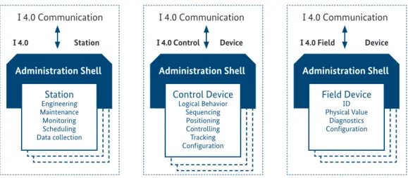
Looking at the I4.0 and IM definitions, there are in principle three kinds of I4.0 elements of relevance to the subject matter discussed here:
When looking at the specific constraints of functional safety, the following should be anticipate:
Looking at the specific safety constraints, the safety parameters will be attributed to the physical device(s). Either the physi- cal device or the administration shell or a combination of both is protected by the security aspects.
Figure 6: Different kinds of communications related I4.0 elements
I 4.0 Communication I 4.0 Station
Administration Shell Station
Engineering Maintenance Monitoring Scheduling Data collection
I 4.0 Communication I 4.0 Control Device
Administration Shell Control Device
Logical Behavior Sequencing Positioning Controlling Tracking Configuration
I 4.0 Communication I 4.0 Field Device
Administration Shell Field Device
ID Physical Value
Diagnostics Configuration
I 4.0 Communication I 4.0 Device
Administration Shell
DEVICE Logical Behavior
Sequencing Positioning Controlling Tracking
STATION Engineering Maintenance Monitoring Scheduling Data Collection
Configuration
I 4.0 Communication I 4.0 Device
Administration Shell
SAFETY DEVICE Device Information
Physical Behavior (e.g. PFD, PFH, SFF, HFT)
Systematic behavior (e.g. systematic capabilities)
SAFETY DEVICE Device Information
Physical Behavior (e.g. PFD, PFH, SFF, HFT)
Systematic behavior (e.g. systematic capabilities)
Plus Device Information SAFETY DEVICE Device Information
Physical Behavior (e.g. PFD, PFH, SFF, HFT)
Systematic behavior Plus Device Information
I 4.0 Communication I 4.0 Safety Device
Administration Shell
SAFETY DEVICE Physical Behavior (e.g. PFD, PFH, SFF, HFT)
Systematic behavior (e.g. systematic capabilities) Logical behavior(e.g. functional design)
Plus Device Information
SAFETY STATION Remote Engineering Remote Maintenance Remote Overrides Remote Process Model SAFETY STATION Remote Engineering Remote Maintenance Remote Overrides Remote Process Model
I 4.0 Safety Station I 4.0 Communication
Administration Shell
SAFETY STATION Remote Engineering Remote Maintenance Remote Overrides Remote Process Model
7.2.2 Solution
Based on the special considerations for an I4.0 and IM workspace and the specific application, the relevant envi- ronment and perimeter need to be defined. This is neces- sary because achieving the overall safety and the dedicated risk reduction realised though functional safety requires a sufficient level of security to be achieved.
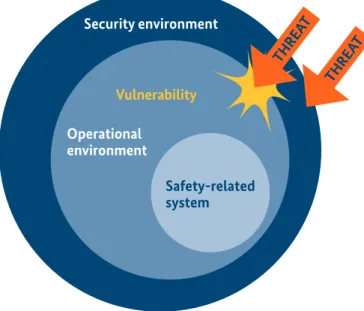
IEC TR 63069 introduces the concept of the security envi- ronment, which provides all security countermeasures nec- essary to sufficiently protect the operational environment of an I4.0 and IM workspace (see Figure 10a below).
Figure 10a: Security environment and its coverage of the operational environment of the system (from IEC 63069)
The security countermeasures are defined based on a secu- rity risk assessment of the security environment for the SM control system. This is required in order to ensure all rele- vant security protection targets, Confidentially, Integrity and Availability (CIA), the safety of the system under con- sideration (I4.0 and IM workspace) and the implemented safety functions.
The security risk assessment relies on the safety risk assess- ment of the I4.0 and IM workspace for determining the safety criticality. This is of particular importance, because for the time being, many of the applications will be realised by products that have rather different levels of security and also different safety features implemented.
7.2.3 Protection of the I4.0 and IM workspace and safety-related installations
When transforming the stipulations of IEC 62443 and IEC TR 63069 into the terminology of I4.0, one of the options is outlined in Figure 11 (see picture below).
It is emphasised that the security environment does not correspond to a security zone, but to all security (counter) measures necessary to ensure sufficient security protection of an I4.0 and IM system, including aspects like defence in depth and the zone concept. These security (counter)meas- ures might be within or external to physical devices in the system.
The essential communication (incl. safety communication) is covered by the (counter)measures of the security environ- ment (see IEC TR 63069).
Figure 11: I4.0 & IM security environment for IM operational environment Security environment
Operational environment
Vulnerability
Safety-related system
THREA T
THREA T
SAFETY RELATED DEVICE
Incorporates features and parameters necessary to support the safety function
STATION
• Engineering
• Maintainance
• MOS
• OOS
STANDARD CONTROLS AND DEVICES
• Could incorporate essential functions (based on security risk management)
• Could be of safety relevance for the system (based on safety risk assessment)
ADMINISTRATION SHELL
FUNCTIONAL SAFETY
I4.0 & SM Workspace protected by security environment
7.2.4 Functional Safety for I4.0 and IM Figure 12: I4.0 & IM workspace
Figure 12 shows an installation of safety-related compo- nents in an I4.0 and IM workspace constituting the opera- tional environment within the meaning of IEC TR 63069.
If the administration shell is safety-related, safety-related communication through the I4.0 and IM workspace is pos- sible, allowing the connection of safety-related devices and stations allocated somewhere in the I4.0 and IM workspace.
If such solutions (as per IEC 62443) are used, the related communication must be investigated for potential attack surfaces regarding security threats. Following the concept of defence in depth and in consideration of the criticality of essential functions as per IEC 62443, different architectural decisions on the implementation might be made.
7.3 Zones & conduits
In an I4.0 and IM workspace, the different components allo- cated at the different levels each communicate with one an- other using open protocols, such as Open Platform Commu- nications United Architecture (hereinafter: OPC UA).
The communication can be organised either in 1-to-1 or m-to-n relations as required by the related business func- tionalities.
The infrastructure design and the layout of zones and con- duits in such solutions need to be developed in line with the results of the security risk assessment, which has to consider the possible impact on the safety risk reduction required by the I4.0 and IM workspace.
7.4 Considerations for safe and secure communication
One of the key elements required to create a digital world is communication. Looking at the integration of safety func- tions, safety-related communication and its integration into a non-safety related communication environment is one of the most important aspects to consider. In addition to the in- dividual I4.0 and IM recommendations, such communication needs to be protected by security measures that cover the recommendations defined for the security environment of the safety devices/stations.
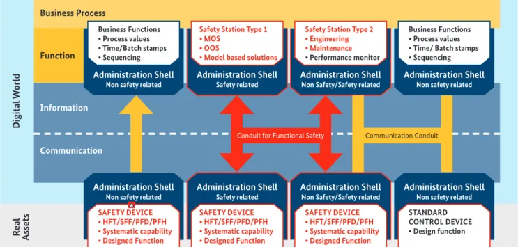
Figure 13:Zones and conduits in I4.0
Business Functions
• Process values
• Time/Batch stamps
• Sequencing
SAFETY DEVICE
• HFT/SFF/PFD/PFH
• Systematic capability
• Designed Function
Safety Station Type 1
• MOS
• OOS
• Model based solutions
SAFETY DEVICE
• HFT/SFF/PFD/PFH
• Systematic capability
• Designed Function
Safety Station Type 2
• Engineering
• Maintenance
• Performance monitor
SAFETY DEVICE
• HFT/SFF/PFD/PFH
• Systematic capability
• Designed Function
Business Functions
• Process values
• Time/ Batch stamps
• Sequencing
STANDARD CONTROL DEVICE
• Design function
Digital WorldReal Assets
Business Process
Function
Information
Communication
Administration Shell
Non safety related
Administration Shell
Non safety related
Administration Shell
Safety related
Administration Shell
Safety related
Administration Shell
Non Safety/Safety related
Administration Shell
Non Safety/Safety related
Administration Shell
Non safety related
Administration Shell
Non safety related Conduit for Functional Safety Communication Conduit
Organisation and business processes Functions
Data
Access to Information
Transition from real to Digital
Physical Things
4 4 4 4
Digital World
Real World
i i i
Due to the constantly escalating threat of cyber-attacks, not least due to enormous attacks conducted in recent years on industrial facilities worldwide, but also the thoughts on I4.0 and IM applications, the demand for secure and safe trans- mission protocols is growing.
The interaction of safety and security plays an important role for the entire automation system, or at least for the safety part of the system, and this applies in particular to industrial communication. In fact, this communication is the link to surrounding systems and from a security point of view is therefore a highly sensitive area in need of protection.
It is IEC 61508 Part 2 which deals with the safety of electronic systems in general and refers to functionally safe communi- cations. This purpose is addressed in IEC 61784-3, which is part of the IEC 61784 series of standards and deals with the communication in industrial processes in general. Other sec- tor-specific standards, such as IEC 61511 or ISO EN 13849, re- fer to IEC 61508 for functionally safe communication or, more recently, to IEC 61784-3 as well.
According to IEC 61784-3, functionally safe protocols have to be able to deal with the following communications errors in line with the black channel principle:
•
Corruption (of messages)•
Unintentional repetition (of messages)•
Incorrect sequence (of messages, e.g. commands in the wrong sequence)•
Loss (of messages)•
Unacceptable delay (message data too old)•
Insertion (messages from unexpected sources)•
Masquerade (messages generated by functionally non- safe elements and treated as functionally safe messages)•
Addressing (delivery of messages to wrong recipients) IEC 61784-3 also lists several measures for dealing with these errors, including sequence numbering, time stamping, time expectation, and connection authentication. An essen- tial point is data redundancy, e.g. by means of Cyclic Redun- dancy Checks (hereinafter: CRC).Along with the characteristics of the actual backup proce- dure, e.g. CRC, an evaluation of the data redundancy effi- ciency must take the Bit Error Probability (hereinafter: BEP) within the communication channel into account.
Standard-compliant implementation of the indicated error control is highly non-trivial.
Secure communication is always relevant when leaving protected networks (protected by the security environment) and passing through public or semi-public networks. This does not only apply, for example, if the internet or GSM is used for communication. It must also be assumed that ex- ternal access is possible when WLAN (Wi-Fi) routes are used.
Security communication in the area of industrial commu- nication is covered by the IEC 62443 series. Overall, the ori- gins of the various methods vastly vary. However, all cryp- tographic methods have one thing in common: they have to withstand critical analysis by other recognised cryptologists in order to gain general acceptance.
Ultimately, it is assumed that, when passing through a pub- lic (note: the specification analysis performed has shown that OPC UA, in contrast to many other industrial protocols, provides a high level of security) communication infra- structure, encryptions and decryptions taking place at vari- ous points (e.g. provider transition) beyond operators’ con- trol are to be applied. ‘Public’ in this sense means that com- munication between different devices and/or stations (see Figure 13) is routed through infrastructure components that are not under control of the I4.0 and IM workspace operator (black channel principle), but that still need to be considered when carrying out the security risk assessment and to be protected by countermeasures from the security environment.
Currently, OPC UA is the only industrial protocol that has comprehensively integrated security features. The German Federal Office for Information Security (Bundesamt für Sicherheit in der Informationstechnik, hereinafter: BSI) has conducted a security analysis of OPC UA. The report of this analysis was published in April 2016.
OPC UA relies on established, modern cryptography and has decided to use TLS. The ‘Main results’ section of the above-mentioned BSI report clearly identifies a basic prob- lem of secure communication:
No systematic errors could be detected.
When analysing the reference implementation, basically the following problems were identified: [...]”
Such work is currently being done in the development of the OPC UA Safety communication protocol (a joint activity by the OPC foundation and the PNO), which will subse- quently be transferred to the IEC. The key aspects of the work for OPC UA safety are:
•
Uses OPC UA client/server (OPC UA pub/sub with or without TSN later on)•
Unidirectional, bidirectional, and multicast communica- tion patterns•
Arbitrary network topology: line, tree, star, ring, mesh, ...•
·Arbitrary structured user data, length: 1-1500 bytes•
Dynamic establishment of safe connections during run-•
timeNo requirements on regular (i.e. non-safe) network participants•
No need for synchronised clocks•
Unlimited number of network components and terminals•
Unlimited data rateThe concept is based on IEC 61784-3 series standards (functional safety for fieldbus)
•
Cyclic communication, watchdog (local clock of the consumer suffices)•
32-Bit CRC-polynomial:•
“Properness” shown for all data lengths between•
1-1500 bytes•
calculated PFH-value suffices for SIL4•
IDs are used to detect authenticity errors such as misdi- rected telegrams•
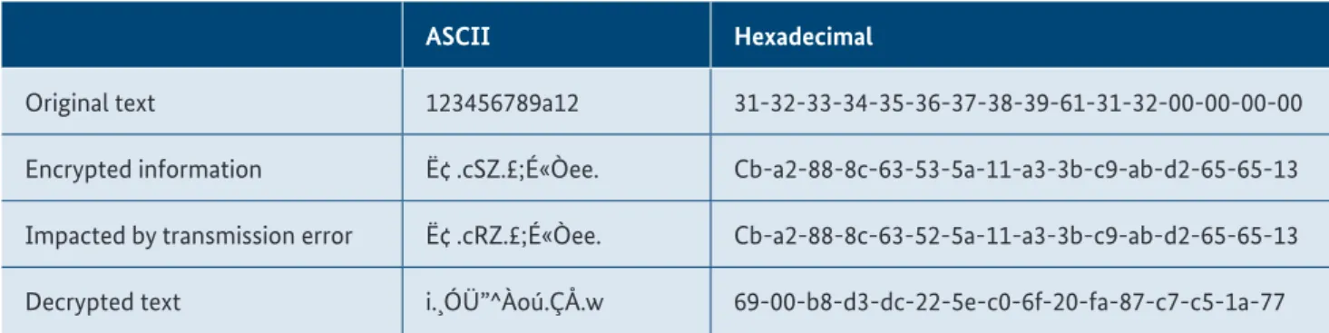
A Monitoring Number (MNR) is used to detect timeliness errorsTable 1: Example of data 1 failure in the safety telegram
In respect to the new complexity of I4.0 and IM, it has to be ensured that fault models (see encryption example below) of functional safe communication are state of the art and are furthermore compatible with the cryptographic meth- ods used to secure communication.
In the meantime, all so-called interferences have to be han- dled by the safety communication. IEC TC65 SC65C WG12 is about to work on a corresponding amendment.
Example of encryption for safe communication:
In this example, we consider an issue that impacts on the performance of the safety-related protocol transmission:
adding a HASH to the transmitted data which keeps the safe protocol untouched and enables standard communication infrastructure to be used. The benefit of such a strategy is that if vulnerability is detected in the HASH, only the infra- structure can be updated, while the safety protocol remains untouched.
This leads us to the following considerations:
Imagine that a short safety telegram is transmitted, which is encrypted. Many safety telegrams only contain 12 bytes. To simplify matters, we will not consider the entire protocol with the associated CRC, headers, etc., but only the pure data content of 12 bytes (1 byte = 1 ASCII character).
•
An error is inserted into the encrypted Data 1.•
The information is then decrypted.After the decryption, it becomes visible that the decrypted text is very different from the original message. If this had been a piece of safety-related information, the bit failure mechanism of the protocol used would have been chal- lenged to address this situation. In our example, 66 out of 128 bits are impacted by the change of 1 bit. The IEC SC65C WG12 is working on this and other issues related to safety communication use cases of the I4.0 and SW workspace.
ASCII Hexadecimal
Original text 123456789a12 31-32-33-34-35-36-37-38-39-61-31-32-00-00-00-00
Encrypted information Ë¢ .cSZ.£;É«Òee. Cb-a2-88-8c-63-53-5a-11-a3-3b-c9-ab-d2-65-65-13 Impacted by transmission error Ë¢ .cRZ.£;É«Òee. Cb-a2-88-8c-63-52-5a-11-a3-3b-c9-ab-d2-65-65-13 Decrypted text i.¸ÓÜ”^Àoú.ÇÅ.w 69-00-b8-d3-dc-22-5e-c0-6f-20-fa-87-c7-c5-1a-77
7.5 Risks due to system complexity and interconnectivity
The increased complexity of automation solutions for an I4.0 and IM environment may potentially lead to an in- creased level of risk that would need to be considered. On the other hand, itis anticipated that the application of I4.0 and IM will create commercial benefits due to the more flexible, seamlessly integrated engineering and production processes used.
The future challenge will be to identify the optimal combina- tion for flexibility, design complexity and maintainability.
The most effective way in which this can be done is by de- fining individual use cases including related structures.
However, even in an integrated I4.0 and IM workspace there will need to be clustered structures so that different areas of applications can be handled as required.
Example: process industry:
The engineering process requirements for a Safety Instru- mented Function (hereinafter: SIF) as per IEC 61511 requiring a lot of activities for the implementation and monitoring of
•
Training of people, functions and equipment•
Design reviews•
Safety assessmentBased on this assumption, the implementation of the SIF, even in an I4.0 and IM environment, will be different from the implementation of a standard automation (non-safety) function.
In order to make sure the additional functionality (which is in effect what I4.0 and IM is) of I4.0 and IM does not lead to uncontrollable complexity, appropriate structural ap- proaches need to be developed and implemented. Especially when looking at axis 3 of RAM,I it can be maintained that the implementation of I4.0 and IM does not necessarily af- fect the complexity at the functional safety level at all. How- ever, this strictly y depends on how such implementation is done and how different functional aspects are taken into consideration during the process of designing a solution.
Example:
When applying the black channel communication principle to interconnect a safety device and a safety station, there will be no difference between an I4.0 and IM application and a con- ventional one; if you decide, however ,to integrate the safety re- lated administration shell required at functional level, you will end up with a level of complexity that is tremendously higher.
In fact, the overall complexity of an I4.0 and IM application is higher than the complexity of an application that does not
follow I4.0 and IM principles. By applying an appropriate de- sign process, such complexity can be mastered
Example: cloud computing:
When using cloud computing, there are 2 possibilities in terms of the underlying principle:
A: If the safety devices connected to the cloud do not sup- port such applications, the cloud needs to be analysed and in this case will be part of the safety system. The cloud will need to comply with the same SIL require- ments applicable for the safety devices and stations.
B: If the safety functions connected to the cloud maintain sufficient fault detection algorithms, a kind of black channel principle may apply when the cloud is not inves- tigated to meet SIL requirements.
Mastering complexity is the key challenge – especially when talking about functional safety. This can be achieved based on more intense cooperation between experts in the areas of functional safety, information technology (hereinafter:
IT) and operational technology (hereinafter: OT) security.
IEC TR 63069 addresses this by introducing a joint security risk assessment and management process making sure that an appropriate security environment can be formed so that systems of functional safety can be operated securely dur- ing their entire lifecycle.
7.6 Risks due to system interoperability
In the event that security vulnerabilities are detected, it is beneficial to be able to eliminate these as quickly as possi- ble. Such corrective action (e.g. patching) may or may not have an impact on the safety function.
Based on this, there are areas where robust (time consum- ing) development processes are not the highest priority. An example of this kind of application is the software for de- vices in the communication infrastructure. In the event that a switch or a router has vulnerability, this has to be cor- rected as soon as possible. If such a device goes on to be in- tegrated into a safety device, such a correction would mean the safety device being modified.
If such measures are kept separated (e.g. by using the black channel communication concept), it would be possible to modify the communication infrastructure without modify- ing the safety implementation.
By following the concept of protecting the operating envi- ronment incl. the essential functions and safety functions from simulation systems hosting the digital twin in the dig- ital space , flexibility can be maintained and even technol- ogy that has not yet been proven in use may be utilised, without the operation and the safety of the I4.0 and IM ap- plication being harmed.
When implementing functional safety and big data, artifi- cial intelligence (hereinafter: AI), internet technology and a new generation of information technology – including fuzzy boundaries – may create an additional risk. However, if they are implemented using a proper strategy as de- scribed above, such additional risks can be minimised.
7.7 Risks due to lack of maturity of intelligent technologies and products
Where new technologies such as AI (or cognitive systems) are used, it is essential to develop a risk determination pro- cess for these technologies.
As long as such processes are not available, the application of current AI solutions requires restrictions to be placed on the scope of their supervised or unsupervised actions. Cur- rently, initial activities are under way to look at the integra- tion of AI in safety applications. This, however, is an area where further research need to be undertaken before safety applications relying on AI are used in an industrial setting.
8 Safety in the
context of security
8.1 Preconditions to be met by the security framework
8.1.1 Domain-specific knowledge
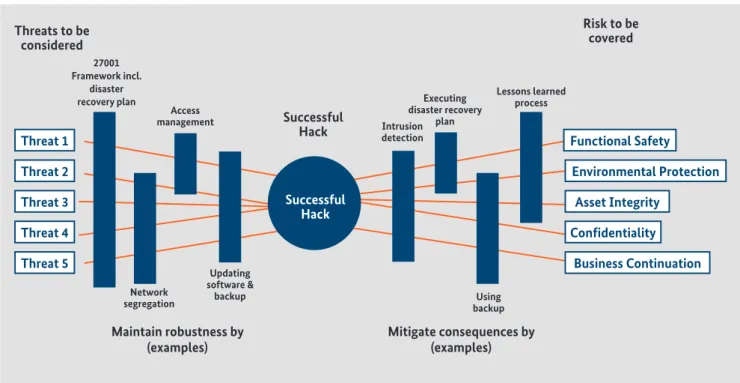
The figure below shows a generic security-related threat-risk model.
•
Threats exploit the vulnerability of ICS•
No countermeasures might represent an intolerable risk (for assets)•
Generally, countermeasures are required to minimise risk (for assets)In addition, in the event that a successful attack takes place on a system, measures to mitigate the consequences of such an attack should be defined.
Figure 14: Context element relationships for security (from IEC 62443-1-1:2009)
Threat 1 Functional Safety
Threat 2 Environmental Protection
Threat 3 Asset Integrity
Threat 4 Confidentiality
Threat 5 Business Continuation
Mitigate consequences by (examples) Maintain robustness by
(examples) Threats to be
considered
27001 Framework incl.
disaster recovery plan
Access
management Successful
Hack Intrusion detection
Executing disaster recovery
plan
Lessons learned process
Network segregation
Updating software &
backup Using
backup
Risk to be covered
Successful Hack
8.1.2 Security grading
Security grading is essential for setting up a comprehensive security framework, as needed in the context of intelligent manufacturing and digital plants. Security grading is a key concept for expressing graded security needs, security re- quirements and, following this , adequate security architec- tures, security by design and graded security tests.
The IEC 62443 standard series provides the adequate basis for this. These standards in particular do not just address Security Levels (hereinafter: SL), but also the contribution of maturity levels towards IACS protection levels.
Three different types of security levels can be defined by the IEC 62443 series:
•
SL (target) – target security level for a zone or conduit•
SL (achieved) – achieved security level of a zone or con-•
duitSL (capability) – security level capability of countermeas- ures associated with a zone or conduit or inherent secu- rity level capability of devices or systems within a zone or conduit.8.1.3 Security requirements
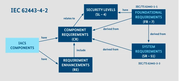
The subsequent figure indicates several types of security- related requirements that are addressed by IEC 62443.
In general, the correlation is as follows:
•
The solution or parts of the solution (based on different threat environment considerations) need to comply with a dedicated target security level (SL-T)•
Relevant components / functions based on their functio- nality need to comply with requirements for a dedicated Security Level (SL-A)A potential gap between SL-T and SL-A needs to be covered via configuration and additional measures like firewalls or encryption devices etc. In addition to security grading, ot- her pre-conditions that need to be met by a security frame- work include considerations of security requirements and support for meeting these requirements. In order to meet these requirements, the following aspects should be sup- ported by a security framework in particular:
•
It should be possible to refine security requirements.•
Security requirements should relate to the security grading, e.g. the SL indicated in the above figure.•
Security requirements should be specific to the main li- fecycle phases.•
It should be possible to trace security requirements to security objectives and security controls, in order to demonstrate that all security requirements have been addressed.•
Security requirements should be sufficiently precise and self-contained so that selected requirements can be grou- ped and forwarded to sub-suppliers along the supply chain.•
Security requirements should take safety requirements into consideration, where applicable. This may similarly relate to quality requirements for the implementation of security controls as to the implementation of safety rela- ted software, firmware, FPGAs, mixed criticality system (virtualised hardware) etc.Figure 15: Different requirement types in the IEC 62443 context
SECURITY LEVELS
(SL – 4) FOUNDATIONAL
REQUIREMENTS (FR – 7)
SYSTEM REQUIREMENTS
(SR – 51) REQUIREMENT
ENHANCEMENTS (RE) COMPONENT REQUIREMENTS IACS (CR)
COMPONENTS
CRs & REs > Target security level that a component is capable of
IEC 62443-4-2
relates to
have
have
have
include
derived from
derived from
derived from IEC/TS 62443-1-1
IEC/TS 62443-3-3