(will be inserted by the editor)
Using GXL for Exchanging Business Process Models
Andreas Winter1and Carlo Simon2
1 Institute for Software Technology, University Koblenz-Landau, D-56070 Koblenz, Uni- versitätsstraße 1, e-mail:winter@uni-koblenz.de
2 Institute for Management, University Koblenz-Landau, D-56070 Koblenz, Universitäts- straße 1, e-mail:simon@uni-koblenz.de
The date of receipt and acceptance will be inserted by the editor
Abstract The GXL Graph eXchange Language is an XML-based standard ex- change language for sharing graph data between tools. GXL can be customized to exchange application specific types of graphs. This is done by exchanging both, the instance graph, representing the data itself, and the schema, representing the graph structure.
Business process models are usually depicted in a graph-like form. This pa- per describes a novel application of GXL to the exchange of business process models. It is shown, how to customize GXL to exchange business process models depicted as Event-driven Process Chains and Workflow nets as examples for the control flow part of business process models. Each level of modeling is exemplar- ily demonstrated from the metaschemas down to instances of graphs.
Key words graphs – Event-driven Process Chains – Petri nets – exchange for- mats – interoperability
1 Introduction
Business Process Managementtypically deals with the description, optimization, and automization of an organization’s business processes integrated into its infor- mation system. In the case of interorganizational processes, business partners have to exchange information about their individual processes and have to agree upon (partially) common processes. Thus, business process models must be exchanged between business partners on base of respectively used business process modeling tools. This is not only the technical task of mutually adapting software but it is also an organizational one affecting their strategic behavior. Hereby, the business pro- cesses of each of the partners specify behavior requested by potential cooperation partners. The verification whether relevant process behavior is still fulfilled in the cooperation is discussed for example in (Simon and Dehnert, 2004).
Consequently, there is a need for process specification exchange formats, i.e.
business process models. Like models in software engineering, also business pro- cess models are typicallygraph based. Therefore, existing exchange formats in this field should be investigated concerning their applicability to business pro- cesses.
This paper introducesGXL – Graph eXchange Languageas a general inter- change format for business processes. GXL (Holt et al., 2000), (Winter, 2002) is an established format in software engineering which, however, has not been used in a business process context yet. GXL overcomes several limitations of current business process exchange formats as discussed in the following Section 2. The reminder of this paper introduces requirements for graph-based exchange formats (cf. Section 3). The foundation of GXL is presented in Section 4. Section 5.1 and Section 5.2 show how GXL is customized to exchange Event-driven Process Chains and Workflow nets. We finish the paper with some concluding remarks.
2 Related Work
There already exist approaches for exchanging business process models. In the following we will discuss languages used to exchange business process models depicted in certain notations, like EPML, PNML, and BPEL, as well as generic exchange notations like XMI.
EPML (Event-driven Process Chains Markup Language)(Mendling and Nuett- gens, 2004), (EPML, 2004), offers an XML-based interchange format especially for Event-driven Process Chains. An XML-based interchange language for various types of Petri nets is given byPNML (Petri net Markup Language)(PNML, 2004), (Billington et al., 2003).
These language specific notations are limited to provide sufficient support for exchanging only EPC or Petri nets. EPML and PNML, both offer means to ex- change business process models including layout information. Due to separation of concerns, contemporary approaches to represent data, strongly separate content and layout information. Thus, an exchange format should also allow to separately store layout information.
Due to economical reasons, one of the currently most widely discussed lan- guages for the specification of business processes is the Business Process Execu- tion Language for Web Services (BPEL4WS or BPEL for short) (Andrews et al., 2003). As the name indicates, BPEL supports an exchange of process information in web service environments. The use of business protocols provides a means to formulate abstractions on internally complex business processes. BPEL does not intend to exchange business process models in general but only such aspects of businesses which are part of the BPEL specification. BPEL is also fixed to its un- derlying view on business processes. So, it does not cover the representation of several aspects of business process graphs like places in Workflow nets. There- fore, a general exchange format should be extendable and adaptable to cope with various modeling concepts used in various business process notations.
A general interchange format is given by XMI (XML meta data interchange) (OMG, 2000). To provide an adaptable exchange language XMI is based on meta-
modeling techniques. But, the used approach comes along with different docu- ment type definitions for different modeling approaches. Usually, these document definitions are rather complex and contain a vast number of (unnecessary) XML elements. Additionally, XMI requires different document types for schemas and instances. Depending on the intended usage, a schema has to be represented as an XML-instance of its schema or as a document type definition. A generally appli- cable and adaptable exchange format for business process models should provide a common notation independently from the current use of a model. Furthermore, exchange formats should also economize with document size.
The development of GXL aimed at simplicity and distribution in different do- mains of exchanging graph based data. Thus, GXL is not restricted to only one specific modeling language. The GXL format for exchanging both, instance and schema data, is kept very simple to avoid unneeded overhead and to keep GXL documents as short as possible. Therefore, GXL can be viewed as an alternative way to exchange business process models which is simple to use and generally applicable.
3 Exchanging models as graphs
Graphsare widely used for representing and analyzing structured data in vari- ous areas. They combine visual descriptiveness and clearness with mathematical foundation leading to efficient data-structures and -algorithms (e.g. (Tutte, 2001;
Valiente, 2002)). Thus, a great variety of tools relies on various kinds of graph based structures. Offering a generally applicable means for exchanging graph based structuresprovides a broad basis for data exchange. A general and widely accepted interchange format for graphs has to fulfill various demands (cf. (Koschke et al., 1998)).
Adaptability: there exist several problem-related graph models such as trees, di- rected or undirected graphs, node and edge attributed graphs, node and edge typed graphs, hypergraphs, hierarchical graphs, or combinations of these. A standard graph exchange language would need to be flexible enough to be an intermediary for these and other graph models.
Exchanging data also requires to agree on the kind and structure of the data to be interchanged. Next to exchanging data, an exchange language has to pro- vide an appropriate means to exchange structural information on data, e. g. the specification of graph structures.
Processability: the efficiency of exchange formats refers to the exchange process rather than the efficient usage of that data in certain applications (Blaha, 2004).
Thus, each of the tasks 1) graph generation from stored data, 2) the actual exchange, and 3) the import must be conducted rapidly. For this, a set of tools supporting its usage must come along with a graph exchange language.
Distribution: standard exchange formats are only useful, if they are supported by a large number of tools. This demands that graph exchange languages support various components such as graph generation, analyzing (by applying graph algorithms), transformation, and visualization.
GXLwas developed to fulfill these requirements:
Adaptability: GXL represents node/edge typed attributed ordered directed graphs (TGraphs) (Ebert et al., 1996) extended byhierarchy(Busatto, 2002) andhy- pergraphs(Berge, 1976). Thus, GXL covers most of usually used graph struc- tures.
GXL supports both, exchanging graph structure (graph schema) and the ac- tual graphs (instance graph). By mapping graph structures (depicted as class diagrams) to graphs in a standardized manner (Winter, 2002) GXL exchanges instance and schema information by using the same mechanisms.
Processability: GXL graphs and schemas are exchanged as XML(W3C, 2000) streams following the GXL document type definition (Winter, 2002) or the GXL XML Schema specification (GXL, 2004). The GXL DTD is defined plain and simple requiring 18 XML-elements only.
GXL gains profit from a variety of already existing XML tools like the Xerces parser for reading or Xalan (Apache, 2004) for manipulating GXL documents.
Special GXL tools exist as for example for validating GXL documents (Kacz- marek, 2003). The only limitations of GXL are those resulting from the use of XML.
Distribution: GXL was proposed as standard exchange format in software reengi- neering at the Dagstuhl Seminar onInteroperability of Reengineering Toolsin January 2001 (Dagstuhl Seminar 01041, 2001). It also builds the basis of the GTXL exchange language for Graph Transformation System (Taentzer, 2001) (GTXL, 2001). A still growing list of currently more than 40 tools e. g. for reengineering, graph transformation, or graph drawing supporting GXL can be found at (GXLTools, 2004).
Summarizing, GXL can be viewed as an adaptable, easily processable, and widely distributed standard exchange language for graphs.
GXL is also applicable as a language to exchange Business Process Mod- els. Within such models, the work performed within businesses is described and put into a structure. Additionally, the binding of resources like humans or ma- chines to specific activities is expressed. Business processes are usually depicted using graphical languages. In the following, we focus on languages modeling dy- namic aspects of business processes. These languages include Event-driven Pro- cess Chains (Scheer, 1994b) and Petri net based approaches like Workflow nets (van der Aalst, 1996). Two examples which emphasize the specific modeling philo- sophies behind these modeling languages are used to demonstrate the applicability of GXL which allows to handle both types without any deficits.
For exchanging process models among different modeling environments and workflow management systems, formal exchange languages are required. Since Event-driven Process Chains and Petri net diagrams provide structural informa- tion, they are typically viewed as graphs. Thus, GXL as a graph exchange language is a proper means for exchanging such models.
4 GXL Graph eXchange Language
GXL is an XML based configurable exchange format for graphs. It can be adapted to a broad variety of different types of graphs and hypergraphs. The adaptability of GXL is based onmetaschemasspecifying the required graph structure. Thus, GXL representations of graphs typically consist of two parts: in a first part, the actual graphis specified, and, in a second (optional) part the graph structure is defined in agraph schema.
GXL originates in an exchange format for graph-based tools. It is applied to provide interoperability between various tools used in software-engineering. Here, we present a novel application of GXL for the exchange of visual business process models. To introduce the modeling concepts of GXL and its metamodeling facil- ities, the following section shows a plain example business process model and its GXL representation. A more complete version of this business process depicted as a Workflow net is given in section 5.2. Section 4.1 explains how business process models are mapped to graphs and how graph data is represented in GXL streams.
The definition and exchange of graph schemas as special GXL graphs is presented in section 4.2.
4.1 Exchanging Graphs with GXL
GXL supports the exchange of directed and undirected graphs consisting of typed, attributed, and ordered nodes, edges and hyperedges, incidences, and hierarchical subgraphs.
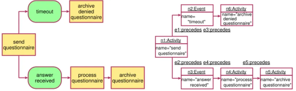
Figure 1 depicts an exemplary plain business process modell describing the handling of questionnaires. The business process shows some activities (send ques- tionnaire,process questionnaire,archive questionnaire,archive denied question- naire) and some events (timeout,questionnaire received) which are connected by some arcs depicting the flow of control.
timeout
answer
received process
questionnaire archive questionnaire questionnairesend
archive denied questionnaire
Fig. 1 a simple business process . . .
name=
"timeout"
n2:Event
e3:precedes e1:precedes
e2:precedese4:precedes e5:precedes
name="answer received"
n3:Event
name="process questionnaire"
n4:Activity name="archive denied questionnaire"
n6:Activity
name="send questionnaire"
n1:Activity
name="archive questionnaire"
n5:Activity
Fig. 2 . . . represented as directed, typed, at- tributed graph
Models like this can easily be depicted as graphs. Each object (here activities and events) are represented by nodes and connections between them (here control
flow arcs) by edges. A graph representation of that map is thedirected, node- and edge typed, node attributed graphdepicted as object diagram in Figure 1.
The graph consists of two different kinds of nodes. Nodes of classActivityde- pict activities or subprocesses andEvent-nodes emphasize states during process- ing. Both,Activity- andEvent-nodes are characterized by their names. Edges of typeprecedesindicate the relative order of activities processing or events occur- ring.
GXL provides constructs for representing and exchanging such graphs. For this, constructs are required to represent nodes, edges, incidences, node- and edge- classes, and node-attributes.
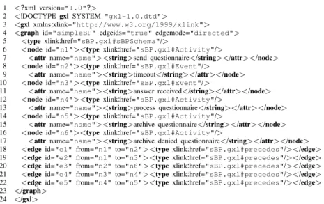
Figure 3 depicts the complete GXL document representing the graph from Fig- ure 1. The first two lines specify the used XML version and refer to the GXL docu- ment type definition (gxl-1.0.dtd). The GXL DTD can be found at (Winter, 2002) and its XML-schema version is given at (GXL, 2004).
1 <?xml version="1.0"?>
2 <!DOCTYPEgxlSYSTEM "gxl-1.0.dtd">
3 <gxlxmlns:xlink="http://www.w3.org/1999/xlink">
4 <graphid="simpleBP"edgeids="true"edgemode="directed">
5 <typexlink:href="sBP.gxl#sBPSchema"/>
6 <nodeid="n1"><type xlink:href="sBP.gxl#Activity"/>
7 <attrname="name"><string>send questionnaire</string></attr></node>
8 <nodeid="n2"><type xlink:href="sBP.gxl#Event"/>
9 <attrname="name"><string>timeout</string></attr></node>
10 <nodeid="n3"><type xlink:href="sBP.gxl#Event"/>
11 <attrname="name"><string>answer received</string></attr></node>
12 <nodeid="n4"><type xlink:href="sBP.gxl#Activity"/>
13 <attrname="name"><string>process questionnaire</string></attr></node>
14 <nodeid="n5"><type xlink:href="sBP.gxl#Activity"/>
15 <attrname="name"><string>archive questionnaire</string></attr></node>
16 <nodeid="n6"><type xlink:href="sBP.gxl#Activity"/>
17 <attrname="name"><string>archive denied questionnaire</string></attr></node>
18 <edgeid="e1" from="n1"to="n2"><typexlink:href="sBP.gxl#precedes"/></edge>
19 <edgeid="e2" from="n1"to="n3"><typexlink:href="sBP.gxl#precedes"/></edge>
20 <edgeid="e3" from="n2"to="n6"><typexlink:href="sBP.gxl#precedes"/></edge>
21 <edgeid="e4" from="n3"to="n4"><typexlink:href="sBP.gxl#precedes"/></edge>
22 <edgeid="e5" from="n4"to="n5"><typexlink:href="sBP.gxl#precedes"/></edge>
23 </graph>
24 </gxl>
Fig. 3 GXL representation of Figure 2
The body of the document is enclosed in a <gxl>element. Line 3 includes the xlink-namespace, which is required for referring to external XML documents.
Graphs are enclosed in<graph>elements. Line 4 introduces the graph assim- pleBP, specifies that edges must have identifiers, and that the graph is interpreted as a directed graph. Nodes and edges are represented by<node>and<edge>
elements, both located by theirid-attribute. Incidences of edges are stored infrom andtoattributes within<edge>tags. These refer to the graph elements represent- ing origin and end of an edge.
<node>and <edge> elements may contain further attribute information,
stored in<attr>elements.<attr>elements describe attribute names and values.
Like OCL (Warmer and Kleppe, 1998), GXL provides<bool>,<int>,<float>, and<string>attributes. Furthermore, enumeration values (<enum>) and URI- references (<locator>) to externally stored objects are supported. Attributes in GXL might also be structured. Here, GXL offers composite attributes like se- quences (<seq>), sets (<set>), multi sets (<bag>), and tuples (<tup>).
Graphs and graph elements may refer to the according schema information, stored in<type>elements. Using xlink (W3C, 2001)<type>elements refer to a GXL-document defining the schema (heresBP.gxl) and the appropriate node or edge class. An extract of the GXL stream for that schema is shown in Figure 6. The relation between GXL graphs and their according schema can be checked within the GXL framework using the GXL validator (Kaczmarek, 2003).
In addition to the GXL features used in Figure 3, GXL provides the exchange of hypergraphs and hierarchical graphs. More information on exchanging various kinds of graphs can be found at (Winter, 2002).
4.2 Exchanging Graph Classes with GXL
Graphs like the one depicted in Figure 2 contain nodes representing activities and events. They are connected by edges representing logical or temporal relations be- tween activities and events. Exchanging graphs this way requires knowledge about that structure. A graph schema defining the structure of graphs like the previous example is shown in Figure 4. The graph schema is depicted as an UML class diagram (Booch et al., 1999) where classes define node classes and associations define edge classes.
Event
Activity BPConcept
name : string precedes
*
*
<<abstract>>
Fig. 4 Graph schema
The graph schema defines an abstract node classBPConceptand its specializa- tionsEventandActivityfor modeling the relevant business process concepts event and activity. Nodes of class BPConcept are attributed by a string valued name attribute. All nodes may be connected by edges of edge classprecedes.
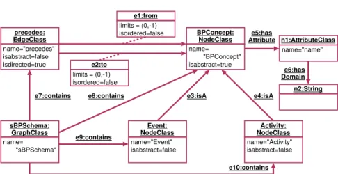
Since class diagrams are structured information themselves, they can be repre- sented as graphs as well. For exchanging graph schemas, GXL uses a predefined way to translate schemas into graphs. Graphs representing schema information fol- low theGXL Metaschema(Winter, 2002). A graph representation of the schema in Figure 4 is depicted in Figure 5.
Node classes and edge classes are modeled by NodeClass-nodes andEdge- Class-nodes. Their name attribute determines the node and edge classes’ name.
e6:has Domain e5:has Attribute
e7:contains
BPConcept:
NodeClass name=
"BPConcept"
isabstract=true
n1:AttributeClass name="name"
name="taxi"
isabstract=false isdirected=false precedes:
EdgeClass name="precedes"
isabstract=false
isdirected=true e2:to
limits = (0,-1) isordered=false
e1:from limits = (0,-1) isordered=false
sBPSchema:
GraphClass name=
"sBPSchema"
Event:
NodeClass name="Event"
isabstract=false
Activity:
NodeClass name="Activity"
isabstract=false e4:isA
e3:isA n2:String
e9:contains
e10:contains e8:contains
Fig. 5 Graph schema represented as Graph
For example, node classBPConceptis represented by theNodeClassnode with OIDBPConceptand edge classprecedesis depicted by theEdgeClassnode with OIDprecedes. Attribute isabstractindicates whether a class is treated as ab- stract (cf. abstract node classBPConcept) andisdirected=truelabels directed edge classes.fromandto-edges connectEdgeClasseswith the incidentNodeClasses. Their attributes contain multiplicities (limits) and indicate the treatment of inci- dences as ordered (isordered). Attribute information is modeled byAttributeClass nodes. They can be connected to both, node and edge classes by hasAttribute edges.hasDomainedges link to attribute domains (here: theStringnode). GXL provides generalization of node and edge classes byisA-edges; cf. edgee3con- nectingEvent:NodeClass andBPConcept:NodeClass. The complete graph class is represented by aGraphClassnode which collects its node and edge classes bycontainsedges.
Graph classsBPSchemain Figure 5 contains node classesBPConcept,Event andActivityand edge classprecedes. GXL instances matching that schema refer to these nodes as schema references, e. g. noden1in Figure 3 (line 6) refers to node Activityin the corresponding schema identifyingn1as an activity.
Like all GXL graphs, the schema graph in Figure 5 can also be stored as an XML stream following the GXL definition. An extract of that GXL document is depicted in Figure 6. Graphs modeling schema information are instances of the GXL-Metaschema whose GXL representation is stored athttp://www.gupro.
de/GXL/gxl-1.0.gxl. Thus, all schema references link to nodes of that file:
e. g. nodeBPConcept:NodeClassrefers to the definition of its type in the GXL- Metaschema (line 10). Analogously, lines 18-22 show the definition ofedgeClass precedes.precedesedges connectBPConceptnodes. These incidences are mod- eled by edgese1ande2(lines 24-31). The specialization ofBPConceptintoEvent is depicted by an appropriateisAedge (lines 33-34). Each GXL document defin- ing a graph schema possesses at least oneGraphClassnode representing the graph class itself. Lines 6-8 denote theGraphClassnode for the graph class. It is con- nected to all of its node and edge classes (e. g. lines 36-37).
1 <?xml version="1.0"?>
2 <!DOCTYPEgxlSYSTEM "http://www.gupro.de/GXL/gxl-1.0.dtd">
3 <gxlxmlns:xlink="http://www.w3.org/1999/xlink">
4 <graphid="sBP"edgeids="true"edgemode="directed">
5 <typexlink:href="http://www.gupro.de/GXL/gxl-1.0.gxl#gxl-1.0"/>
6 <nodeid="sBPSchema">
7 <typexlink:href="http://www.gupro.de/GXL/gxl-1.0.gxl#GraphClass"/>
8 <attrname="name"><string>sBPSchema</string></attr></node>
9 <nodeid="BPConcept">
10 <typexlink:href="http://www.gupro.de/GXL/gxl-1.0.gxl#NodeClass"/>
11 <attrname="name"><string>BPConcept</string></attr>
12 <attrname="isabstract"><bool>true</bool></attr></node>
13 <nodeid="Event">
14 <typexlink:href="http://www.gupro.de/GXL/gxl-1.0.gxl#NodeClass"/>
15 <attrname="name"><string>Event</string></attr>
16 <attrname="isabstract"><bool>false</bool></attr></node>
17 . . .
18 <nodeid="precedes">
19 <typexlink:href="http://www.gupro.de/GXL/gxl-1.0.gxl#EdgeClass"/>
20 <attrname="name"><string>precedes</string></attr>
21 <attrname="isabstract"><bool>false</bool></attr>
22 <attrname="isdirected"><bool>true</bool></attr></node>
23 . . .
24 <edgeid="e1" from="precedes"to="BPConcept">
25 <typexlink:href="http://www.gupro.de/GXL/gxl-1.0.gxl#from"/>
26 <attrname="limits"><tup><int>0</int><int>−1</int></tup></attr>
27 <attrname="isordered"><bool>false</bool></attr></edge>
28 <edgeid="e2" from="precedes"to="BPConcept">
29 <typexlink:href="http://www.gupro.de/GXL/gxl-1.0.gxl#to"/>
30 <attrname="limits"><tup><int>0</int><int>−1</int></tup></attr>
31 <attrname="isordered"><bool>false</bool></attr></edge>
3233 <edgeid="e3" from="Event"to="BPConcept">
34 <typexlink:href="http://www.gupro.de/GXL/gxl-1.0.gxl#isA"/></edge>
35 . . .
36 <edgeid="e7" from="sBPSchema"to="precedes">
37 <typexlink:href="http://www.gupro.de/GXL/gxl-1.0.gxl#contains"/></edge>
38 . . .
39 </graph>
40 </gxl>
Fig. 6 GXL representation of schema graph in Figure 5 (extract)
Since the GXL Metaschema is a schema, it is represented by a GXL docu- ment referring to the GXL Metaschema, namely itself. The GXL Metaschema, its representation as UML-class diagram and as GXL document is documented at (GXL, 2004).
4.3 Customizing GXL
The previous sections shortly introduced GXL for representing graph data and associated graph schemas. Both, graph instances and graph schemas are exchanged by the same type of XML document following the GXL specification.
Using GXL for exchanging graph data in a particular application domain re- quires to constrain the form of graphs, i. e. specifiying the types of nodes and edges.
GXL is customized by defining graph schemas. These schemas determine
– which node, edge, and hyperedge classes (types) can be used,
– which relations can exist between nodes, edges, and hyperedges of given (node, edge and hyperedge) classes,
– which attributes can be associated with nodes, edges, and hyperedges, – which graph hierarchies are supported, and
– which additional constraints (such as ordering of incidences, degree restric- tions) have to be imposed.
These constraints specialize the graph structure to represent the domain of in- terest. It is useful to standardize graph structures for particular domains byGXL Reference Schemas. Currently, those GXL reference schemas are defined for var- ious reverses engineering domains e. g. (Lethbridge et al., 2004) defines a GXL reference schema for language independent representation of source code data and (Ferenc et al., 2001; Ferenc and Beszédes, 2002) deal with the definition of a GXL reference schema for C++-abstract syntax trees.
Tailoring GXL for exchangingBusiness Process Modelsrequires to specify GXL Schemas for Business Process Models. Depending on the used modeling ap- proach and notation, these schemas define the relevant modeling concepts and their associations. The following section introduces candidates for those GXL schemas for customizing GXL to exchangeEvent-driven Process ChainsandWorkflow nets as a variant of Petri nets. We demonstrate how to customize GXL to exchange two different process models known from literature, which stress the different mod- eling philosophies behind these approaches. Customizing GXL to express Event- driven Process Chains and Workflow nets did not require to extend GXL. GXL’s metamodel based adaptability provides using the same language for exchanging business process models in both notations.
5 Representation of Business Process Models
Business process models must provide the following views on organizations: con- trol flow, information, and organizational structure (Scheer, 1994b), (Jablonski et al. , 1997, p 98ff). In this paper we focus on the control flow part, which is modeled either in Event-driven Process Chains or in Petri nets. All other aspects of business process models can be treated analogeously by defining convenient metamodels. A collection of GXL compliant metamodels for various visual languages describing control flow, information, and organizational structures is given in (Winter, 2000).
Several notations have been introduced which all profit from the ability of Petri nets to represent both the actual process as well as business resources like humans or information. A brought overview over published approaches to model- ing business processes with Petri nets is given by Janssens, Verelst and Weyn in (Janssens et al., 2000). Beside the descriptive nature of models and the ability to verify the models either with standard Petri net analyzing techniques or against special process specifications (Simon, 2002a; Simon, 2002b), their automatic ex- ecution within a Workflow Management System (WfMC, 1996) is one of their aims.
Both the variety of description languages as well as the necessity to execute the models in Workflow Management Systems require formal languages that can be used to exchange models among different platforms. In the following we demon- strate how to use GXL as such a language.
We have chosen Event-driven Process Chains (EPCs) introduced in (Keller et al., 1992) and Workflow nets (WF nets) introduced by van der Aalst (van der Aalst, 1996), (van der Aalst and van Hee, 2002) as exemplary notations for business pro- cess modeling to illustrate our approach. We define a metaschema for each of these notations and demonstrate the instantiation of these models by examples.
5.1 Exchanging Event-driven Process Chains with GXL
Event-driven Process Chains (EPCs) (Keller et al., 1992) are one central concept within the ARIS business process framework basing on stochastic networks and Petri nets (Scheer, 2000).
Events (depicted by hexagons) and functions (depicted by ovals) are the basic elements of EPCs which are connected by a flow relation and additional connec- tions used to span complex process structures. Figure 7 shows the basic elements of EPCs as defined in (Scheer, 1994a).
.......... E1 ....
....... .
...
...... E2 ....
.......
. ...
...
...
...
...
...R..........
∧............
...
...
.... ...
...
...
...
?
F
When eventE1andE2occur, functionFis launched
....
...... E1 ....
....... .
...
...... E2 ....
.......
. ...
...
...
...
...
...R..........
∨............
...
...
.... ...
...
...
...
?
F
When eventE1orE2occur, functionFis launched
.......... E1 ....
....... .
...
...... E2 ....
.......
. ...
...
...
...
...
...R..........
∧............
...
...
......
. ...
...
..?
∧............
...
...
......
. ..........
...
...
...
...
...
.R
F1
F2
When eventE1andE2occur, functionsF1andF2are launched
....
...... E1 ....
....... .
...
...... E2 ....
.......
. ...
...
...
...
...
...R..........
∨............
...
...
......
. ...
...
..?
XOR............
...
...
......
. ..........
...
...
...
...
...
R
F1
F2
When eventE1orE2occur, either functionF1orF2is launched Fig. 7 Event relationships in EPC (Scheer, 1994a)
EPCs support branching and merging control flows. Logical operators (∧,∨, xor) depicted in circles indicate how incoming events are combined to enable function execution, how control flow is shared between concurrent functions, and how different functions result in an event. Furthermore, EPCs provide sequences of control flow operators. In general, control flows in EPCs span bipartite (hyper)- graphs, where functions follow on events and events follow on functions.
Syntax and semantics of EPCs is explained somehow vague. There exist var- ious approaches to resolve this uncertainness by specifying the concrete syntax
(e. g. (Staud, 1999)) and semantics ((Nüttgens and Rump, 2002), (van der Aalst et al., 2002)) of EPC. In the following, we will not address that problem; we only specify the EPC-syntax as far as this is required to explain the idea of using GXL for exchanging EPC-based process models and assume an intuitive EPC semantics.
5.1.1 Metaschema for Event-driven Process Chains Adapting GXL to exchange EPCs requires the specification of aGXL schema for Event-driven Process Chains.
This schema has to cover all modeling concepts and their associations used in EPC.
In (Scheer, 2000) all modeling techniques used within the ARIS business pro- cess framework are introduced along their metaschemas. The EPC metaschema in (Scheer, 2000, p 128) was designed to roughly describe modeling techniques and their relationships to other modeling techniques. Although this model is sound within the ARIS business process framework, it is not appropriate for GXL ex- change and has to be adapted. Especially, it does not cover different kinds of control flows between events and functions which have to be distiguished while exchanging business processes.
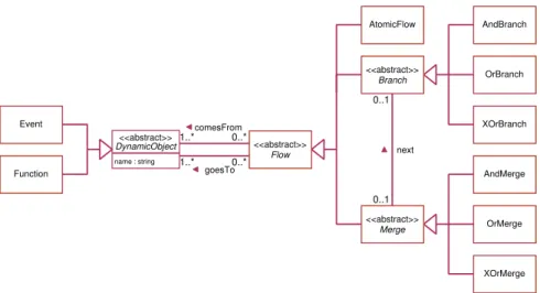
A useful metaschema for defining the exchange of EPC models has to specify the complete syntax of EPC. It has to cover concepts for modelingevents,functions and the various operators oncontrol flow. Figure 8 shows the class diagram part of a GXL schema for EPC derivated from (Winter, 2000, p 119). To explain the idea of exchanging business process models with GXL, this schema is restricted to those EPC concepts described in this paper. A complete GXL schema for EPC should also contain concepts to exchange conditions, messages and hierarchies.
1..*
AndBranch
OrBranch
XOrBranch
AndMerge
OrMerge
XOrMerge
<<abstract>>
Flow
AtomicFlow
<<abstract>>
Branch
<<abstract>>
Merge name : string
Event
Function 1..* goesTo
0..*
0..*
0..1
0..1 next comesFrom
<<abstract>>
DynamicObject
Fig. 8 GXL schema for event-driven process chains
EventsandFunctionsare connected byFlows.comesFromandgoesTo-edges express the directed flow of control betweenEvents,FunctionsandFlows.Flows are distinguished inAtomicFlowslinking from one event to one function or vice versa, in Branchesbranching control flow to various events or functions, and
inMerges joining control flow from various events or functions. Branches and Merges occur in their∧,∨, andxor-variants. Direct sequences of flows between merges and branches (cf. Figure 7) are modeled bynext-edges.
Further constraints add syntactical restrictions to a metaschema. For instance, these constraints ensure that functions and events alternate on the control flow, that branches have one incoming and many outgoing connections, or that merges have many incoming and only one outgoing connection. These constraints are not required to exchange graphs with GXL, but they are mandatory to decide if an EPC model conforms its syntactic definition. Complete metaschemas for EPC with their class diagram and constraint part are given in (Winter, 2000, p 192). These schemas also include hierarchies of EPC and the embedding of EPC in multi- perspective modeling environments.
A metaschema like the one in Figure 8 controls the exchange of EPC business process models via GXL. According to the GXL metaschema the EPC schema is exchanged by an suitable GXL graph (cf. Section 4.2).
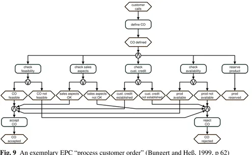
5.1.2 Exemplary EPC in GXL Exchanging an EPC with GXL is based ontrans- lating the EPC diagram into a GXL graph according the metaschema given in Figure 8. In the following, we will demonstate this with an example EPC mod- eling a business process for processing customer orders (Bungert and Heß, 1999, p 62) in Figure 9.
sales aspects
OK sales aspects
not OK cust. credit established
cust. credit
not established prod
available prod not
available prod
reserved CO
feasible CO not
feasible check
feasibility check sales
aspects check
cust. credit check
availability reserve
product
accept CO acceptedCO
reject CO rejectedCO customer
calls
CO defined define CO
Fig. 9 An exemplary EPC “process customer order” (Bungert and Heß, 1999, p 62) Business process “process customer order” starts with a customers call. After defining the order, control flow branches into concurrent activities which perform various tests. Depending on their results, the customer’s order is either accepted or rejected.
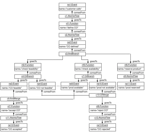
Figure 10 shows an extract of the GXL graph representing the EPC depicted in Figure 9. Events are modeled byEventand Functions byFunctionnodes: e. g. node ne1:Eventrepresents the eventcustomer callsstarting the business process and nf1:Functiondepicts the first function which defines the customer order (define CO).
ne1:Event name="customer calls"
....
...6comesFrom
c1:AtomicFlow goesTo . ...
...
...?
nf1:Function name="define CO"
....
...6comesFrom
c2:AtomicFlow . ...
...
...?goesTo
ne2:Event name="CO defined"
....
...6comesFrom
c3:AndBranch .
...
...
...?goesTo
......................................................................................................................
.... ....... .
...
...
...?goesTo
. ...
....
...
.
...
...
...
...
...
...
...
?goesTo
. ...
nf2:Function name="check feasibility"
....
...6comesFrom
nf5:Function name="check availability"
....
...6comesFrom
nf6:Function name="reserve product"
....
...6comesFrom
c4:OrBranch .
...
...
...?goesTo ..........?goesTo
c7:OrBranch .
...
...
...?goesTo ..........?goesTo
c8:AtomicFlow . ...
...
...?goesTo
ne3:Event name="CO feasible"
. ...
...
...6comesFrom
ne4:Event name="CO not feasible"
. ...
...
...6comesFrom
.........................................................................................................................................................................
.
... ne9:Event
name="prod available"
. ...
...
...
...
6comesFrom
. ...
ne10:Event name="prod not available"
....
...6comesFrom
ne11:Event name="prod reserved"
c9:AndMerge . ...
...
...?goesTo
nf7:Function name="accept CO"
....
...6comesFrom
c11:AtomicFlow. ...
...
...?goesTo
ne12:Event name="CO accepted"
c10:OrMerge . ...
...
...
...
...
.
?goesTo
nf8:Function name="reject CO"
....
...6comesFrom
c12:AtomicFlow. ...
...
...?goesTo
ne13:Event name="CO rejected"
Fig. 10 Representation of the exemplary EPC of figure 9 as a UML instance diagram (extract)
On the contrary to the EPC diagram in Figure 9 where atomic flows of control are depicted as directed edges, the EPC metaschema demands modeling atomic flows by nodes. Analogously to merges and branches, AtomicFlow nodes con- nect associated events or functions by comesFromand goesToedges (cf. node c1:AtomicFlow).
Branching the flow of control into various concurrent activities is modeled by AndBranchnodes. For instance, nodec3:AndBranchlinks the (incoming) event CO definedand the (outgoing) concurrent functions by comesFromandgoesTo edges. Analogously, AndMerge and OrMerge nodes collect control flows. E. g.
node c9:AndMergeconjugates the events CO feasible andprod available and proceeds with functionaccept CO.
1 <?xml version="1.0"?>
2 <!DOCTYPEgxlSYSTEM "http://www.gupro.de/GXL/gxl-1.0.dtd">
3 <gxlxmlns:xlink="http://www.w3.org/1999/xlink">
4 <graphid="exampleEPC"edgeids="true"edgemode="directed">
5 <typexlink:href="metaEPC.gxl#epcSchema"/>
6 <nodeid="ne1"><typexlink:href="metaEPC.gxl#Event"/>
7 <attrname="name"><string>customer calls</string></attr></node>
8 . . .
9 <nodeid="nf1"><typexlink:href="metaEPC.gxl#Function"/>
10 <attrname="name"><string>define CO</string></attr></node>
11 . . .
12 <nodeid="c1"><type xlink:href="metaEPC.gxl#AtomicFlow"/></node>
13 . . .
14 <nodeid="c3"><type xlink:href="metaEPC.gxl#AndBranch"/></node>
15 . . .
16 <nodeid="c9"><type xlink:href="metaEPC.gxl#AndMerge"/></node>
17 . . .
18 <edgeid="e1" from="c1"to="ne1">
19 <typexlink:href="metaEPC.gxl#comesFrom"/></edge>
20 . . .
21 <edgeid="e17" from="c9"to="ne3">
22 <typexlink:href="metaEPC.gxl#comesFrom"/></edge>
23 <edgeid="e18" from="c9"to="ne9">
24 <typexlink:href="metaEPC.gxl#comesFrom"/></edge>
25 <edgeid="e22" from="c9"to="nf7">
26 <typexlink:href="metaEPC.gxl#goesTo"/></edge>
27 . . .
28 </graph>
29 </gxl>
Fig. 11 GXL representation EPC graph in Figure 10 (extract)
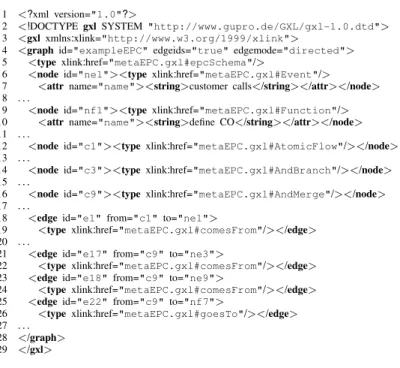
Figure 11 shows the GXL stream representing an extract of the graph in Fig- ure 10. This GXL document refers to the GXL representation of the EPC meta- schema (cf. Figure 8) in line 5. Events, Functions and Flows are stored by suitable
<node>elements (lines 9-16) and their connections are modeled by <edge>
elements. Lines 21-26 show the conjunction (nodec9:AndMergein line 16) of eventsCO feasible(node ne3:Event) andprod available(nodene9:Event) lead- ing to the execution of functionaccept CO(nodenf7:Function).
5.2 Exchanging Workflow nets with GXL
Petri nets (Petri, 1962; Baumgarten, 1996) are a formally sound and well under- stood approach to describe and analyze concurrent and non-deterministic pro- cesses.
Placesrepresent system states or conditions and transitionsmodel specified actions provoking the change of states. Usually places are depicted by circles and transitions by rectangles. Flows connect places and transitions. Like flows in EPC, they span a bipartite graph where places proceed transitions and transitions pro- ceed places. The fundamental modeling constructs of those Place/Transition nets are shown in Figure 12.
When condition s1 and s2 hold, transaction t1 is launched and terminates in condition s3
When condition s4 holds, transactions t2 is launched and terminates in conditions s5 and s6 t1
s1
s2
s3 t2 s6
s4
s5
Fig. 12 Petri net modeling constructs
Process modeling is supported by various different Petri net variants. To ex- plain the exchange of business processes modeled by Petri nets we have chosen Workflow netsdefined by van der Aalst (van der Aalst, 1996) as an example.
5.2.1 Metaschema for Workflow nets Workflow nets are especially suited to de- scribe and analyze workflows. Formally speaking (van der Aalst, 2000), a Work- flow net is a Petri net if
– there exists one input (or source) placei∈P with•i=∅, i.e.iis no postcon- dition of any transition,
– one output (or sink) placeo∈P witho•=∅, i.e.ois no precondition to any transition,
– every nodex∈P∪Tis on a path fromitoo,
whereP denotes the set of places andTdenotes the set of transitions.
Additionally, transitions can be augmented by triggers (time and event) de- scribing additional conditions for firing specific transitions. We will use this ad- ditional construct within our example and, therefore, take into account within our metaschema.
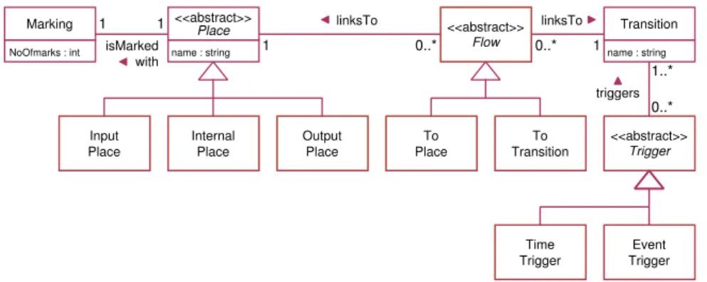
To enable exchanging Workflow nets with GXL, all modeling constructs have to be defined in the GXL metaschema. This metaschema can be viewed as an ex- tension of the metaschema of simple Petri nets already presented in (Winter, 2000) by a means to associate typed triggers to transitions. Figure 13 shows a GXL metaschema for Workflow nets.
name : string
<<abstract>>
Place
Input
Place Internal
Place Output
Place
<<abstract>>
Flow
To
Place To
Transition <<abstract>>
Trigger
Time
Trigger Event
Trigger
1 0..* 0..* 1
linksTo linksTo
1..*
triggers 0..*
name : string Transition isMarked
NoOfmarks : int with
Marking 1 1
Fig. 13 GXL metaschema for workflow nets
Places andTransitions are connected byFlows. According to the definition of workflow nets (van der Aalst, 2000), places are distinguished intoInputPlaces, InternalPlaces, andOutputPlaces. Additional constraints ensure that there exists exactly oneInputPlaceand exactly oneOutputPlacehaving no incoming or outgo- ing transition respectively. Transitions might be triggered by time (TimeTrigger) or by external events (EventTrigger).Placesare associated toMarkingnodes to rep- resent the (initial) marking. In this example, we only model the number of marks on a place. More sophisticated types of markings can be modeled analogeously.
To show that GXL can deal with different meta-modeling styles, we use special subtypes ofFlowsin this example to indicate if a flow links to a place (ToPlace) or to a transition (ToTransition). Corresponding places and transitions are connected bylinksToedges. A further constraint ensures that the resulting graph has to be connected.
Workflow nets can be exchanged with GXL using the Workflow net meta- schema in Figure 13. The metaschema itself is exchanged by its suitable GXL graph (cf. Section 4.2).
register
evaluate
processing required
processingno
process compliant
check processing
processing OK
processing NOK questionairesend
time out process
questionnaire
archive i
c1 c2
c3 c4
c5
c7
c8
c9
c6 o
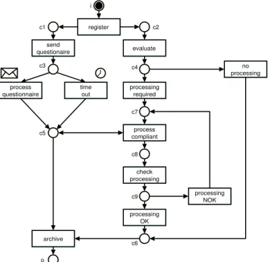
Fig. 14 An exemplary WF-net “processing complaint forms” (van der Aalst, 2000)
5.2.2 Exemplary Workflow net in GXL Figure 14 shows an exemplary Workflow net taken from (van der Aalst, 2000). The net describes the distribution and eval- uation of questionnaires. Although this net is a simple Petri net except the ex-