Controlled Ultrasonic Motor for Servo-Drive Applications
J Maas T Schulte H Grotstollen
University of Paderborn, Institute for Power Electronics and Electrical Drives, FB-14 LEA, Pohlweg 47-49, 33098 Paderborn, Germany, e-mail: maas@lea.uni-paderborn.de
Abstract. This paper deals with an advanced speed control scheme for inverter-fed travelling wave ultrasonic motors. It is implemented as an additional outer control loop of an underlaid voltage and travelling bending wave vector controller and verified by measurements on a prototype drive. The novel speed control is using an inverse contact model by a neural network, trained by measured values of speed and torque, in order to compensate the nonlinear torque generation of the motor. Since the reference values of the bending wave control are calculated from the desired torque value by the neu- ral network, first an open loop control of the drive´s torque is feasible and second common speed con- trol schemes, well performing in common electrical drives, can be applied. Thus, the so equipped ultrasonic motor-drive meets requirements for applications in the field of servo-drives e.g. robotics.
1. Introduction
Piezoelectric ultrasonic motors (USMs), in particular rotary travelling wave type USMs, combine features such as high driving torque at low rotational speed, high holding torque, no electromagnetic interference and are more compact than conventional electromechanical geared motors. Thus, USMs have attracted considerable attention as a new type of actuator for servo-drive applications e.g. as actuator for robotics. The driving principle of trav- elling wave type USMs is based on two orthogonal vibration modes which are excited to their single eigenfre- quency by a piezoelectric ceramic in a first conversion stage. Superimposing both standing waves by proper amplitudes of the feeding voltage and a well defined temporal phase shift between them is producing a travelling bending wave in the stator, which performs elliptic motions of the stator´s surface points. In a second energy conversion process the rotor, pressed against the stator by means of a disc spring, is driven by frictional forces related to the elliptic trajectories [1]. The electrical excitation of motor vibrations is applied by a special designed voltage-source two-phase inverter. Due to dielectric properties of the piezoceramic, characterized by a capacitance in each phase, two inductors have to be added in series. Thus, the USM becomes integral part of a resonant converter feeding the motor with sinusoidal voltages [2].
Due to the complex and widely nonlinear characteristics of USMs intensive efforts of research are required for optimizing and exploiting the power performance of the new actuator. Beside several research activities (e.g.
[1], [2],[5]) in modelling and controlling USMs, a simulation model for the total electro-mechanical system of travelling wave USMs powered by resonant converters is derived in [3]. The basic characteristics of the actuator are studied by the model and a simple cascaded control scheme for speed variable drives is proposed in [6] based on the analysis for the motor´s torque generation in [4]. Drawbacks of this control structure are on one hand cou- plings between the inner controlled quantities (travelling bending wave controller) and on the other hand a non- optimized performance of the speed control due to neglected influences of the USM´s nonlinear torque genera- tion. In order to improve the inner control loops an optimized vector control scheme was proposed in [8] consist- ing of an cascaded voltage and bending wave control and offering new features as outlined in the next section.
The main focus of this paper is given to an advanced speed control implemented as an additional outer control loop. The speed control loop is using an inverse contact model by a neural network (trained by measured values) in order to compensate the nonlinear torque generation of USMs. Since the reference values of the bending wave control are calculated from the desired torque value by the neural network, first an open loop control of the motor´s torque is feasible and second common speed control schemes can be applied.
Reprint of a contributed paper published at the „4th European Conf. on Smart Structures and
Materials - 2nd Int. Conf on Micromechanics, Intelligent Materials and Robotics 1998
(MIMR´98)“, Harrogate, (UK), pp. 701-708
, Juli 6-7,1998.
2. Simulation model and scheme of underlaid voltage and bending wave vector control 2.1. Model of travelling wave ultrasonic motors powered by resonant converters
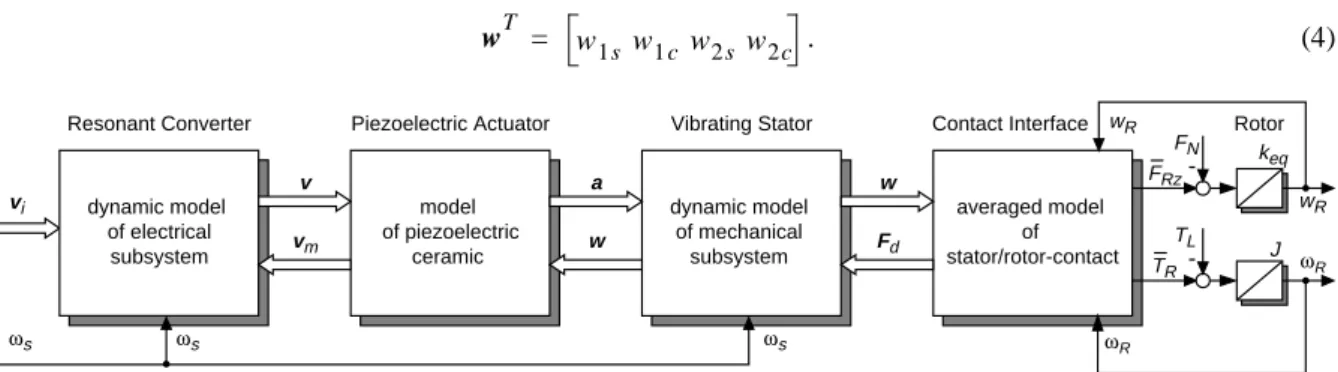
USMs are characterized by a two stage energy conversion process as explained above. By the conversion proc- esses the energy is transferred from electrical input to mechanical output terminals using different types of func- tional modules summarized in Fig. 1. Since the modules consist of electrical as well as mechanical components, the new actuator represents a typical example of a mechatronic system completed by a control for envisaged operation mode and performance. While the stage of high frequency piezoelectric energy conversion can be described by linear transfer properties, the conversions stage of the micromechanical friction interface between stator and rotor displays an extreme nonlinear behaviour. Appropriate models are essential for optimization of the overall drive performance and designing the control. The simulation model derived in [3] describes the total drive system by combining the electrical and mechanical partial models as indicated in Fig. 1. On one hand the simula- tion model reflects the high frequency ultrasonic oscillations of the electrical and mechanical resonant circuits and is therefore indispensable for detailed studies of the motor performance. But on the other hand the model can not be used straight forward when designing the control, because frequency, amplitude and phase modulation is possible only by the feeding resonant converter in contrast to PWM-controlled conventional drives.
In order to obtain an appropriate model for the control design an averaged model is derived in [7] based on the original model in [3]. According to the electrical and mechanical resonant structures, the ultrasonic oscillations of electrical and mechanical state variables contain a major fundamental component shown e.g. by simulations and measurements in [1],[2],[5],[7]. This sinusoidal waveforms can be well approximated by
. (1)
The averaged model in [7] reflects the slow dynamic behaviour (envelopes) of the fast changing original state variables using their time-varying fundamental Fourier coefficients and (in cartesian coordi- nates) as new state quantities of the transformed drive model. This model, which is illustrated in Fig. 1, is pre- destinated for designing the control, since its controlling inputs are the fundamental voltage components
(2) of the two-phase inverter stage obtained by an appropriate vector-modulation concept [8]. The model of the electric subsystem, describing the dynamic behaviour of the resonant converter, comprises state quantities of the series inductors and the capacitances of the piezoceramic and taking care of converter and dielectric ceramic losses. The output quantities are given by the vector of fundamental motor voltages
. (3)
Voltage vector excites the mechanical subsystem of the stator via the inverse piezoelectric effect by acceler- ation vector . The influence of the vibrating stator on the feeding converter by the piezo effect is modelled by the voltage feedback . The static model of piezoelectric conversions stage contains the electromechanical coupling between electrical and mechanical partial models, whereby cross excitation of mechanical vibration modes due to non-perfect bonding and operation of the piezo actuator in practice is taken into account. The dynamics of the vibrating stator are well modelled by a two-mass approximation for the standing waves consid- ering also unsymmetries by a small difference with respect to their eigenfrequencies. In the averaged model the modal amplitudes of both standing waves are represented by vector
. (4)
averaged model of
stator/rotor-contact J ωR
ωR
vi v
TL FRz
FN keq
wR wR
-
TR -
ωs ωs ωs
vm
a w
w Fd dynamic model
of mechanical subsystem model
of piezoelectric ceramic dynamic model
of electrical subsystem
Resonant Converter Piezoelectric Actuator Vibrating Stator Contact Interface Rotor
Figure 1: Simulation model of converter-fed ultrasonic motor divided into its functional modules.
x t( ) =xs( )t sin( )ωt +xc( )t cos( )ωt
x t( ) xs( )t xc( )t
viT = vi1 s vi1c vi2s vi2 c
vT = v1 s v1c v2s v2 c v
a
vm
wT = w1s w1 c w2 s w2c
Modelling the friction interface an elastic model for the contact material is applied describing the nonlinear interaction between the models of stator and rotor. The contact model presented in [3],[4] is derived for the gen- eral case of a non-perfect travelling wave. Impacts of contact forces on the stator are modelled by a modal forc- ing vector . Contact forces acting on the rotor are given by the motor torque opposing the applied load torque and the axial force opposing the normal force applied by the rotor´s disc spring. Under con- sideration of averaging for the vibrating stator the fundamental describing functions of are of interest only, while for the rotor dynamics the dc-values of and are important.
In dealing with dynamics of the rotor, two degrees of freedom must be taken into account. Rotor quantity models the drive´s speed and quantity describes the axial rotor motion. While the high dynamics of the latter is less important for the control, its stationary value has a major impact on contact forces.
As indicated by the signal line for , the inverter´s feeding frequency has an influence on the dynamics of the converter and especially on the stator causing modulation of their fundamental components [7].
2.2. Control schemes
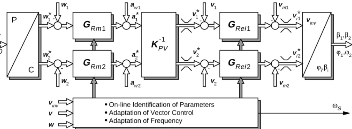
The drive control proposed in [8] is based on the averaged model outlined before. The overall scheme of the novel control is depicted in Fig. 8 by a cascaded structure. Since two dynamic resonant systems characterize the motor´s oscillations, it is obvious to control the motor by means of an inner voltage and an outer travelling bend- ing wave control loop. Controlled quantities are the sine and cosine components of voltages , and modal amplitudes , which are measured by phase-sensitive demodulation circuits. The control is implemented on a DSP-controlled test set-up [6] optimizing the drive performance by the following systematical measures as outlined in [8] in detail:
• The reference values are passed to the vector modulation algorithm in order to calculate the regulating quantities of the two-phase inverter stage. A compensation of mechanical feedback on the converter is introduced. The voltage control is denoted by the controllers .
• A compensation of couplings between mechanical vibrations is achieved by introducing the inverse model of piezoelectric actuator. Thus, an identical vector control scheme can be applied for the bending wave control as used for the voltage control. The command inputs of bending wave con- trol are obtained from reference values of the speed control explained in detail later.
• Remaining regulating quantity of the converter is adapted in such a way, that the vibration modes of the stator are excited at resonance. By this measure the optimal operating point of vibrator is found mini- mizing the voltage demand for excitation which reduces losses of converter and piezo ceramic.
• Utilizing the power performance of the drive control for wide range operations with respect to high dynamic responses (servo-drive applications) an on-line adaptation of control parameters is recommended due to nonlinear contact impacts and temperature influences. While temperature effects influence the electrical as well as mechanical subsystem, contact forces have an impact on the mechanical system only. For on-line identification of slowly-varying plant parameters simple algorithms are proposed in [8]
based on a quasi-stationary evaluation of the transfer matrices obtained from the averaged drive model.
Impacts of fast parameter variations caused by contact forces are almost eliminated by an appropriate modulation of the frequency .
Fd TM
TL FRz FN
Fd TR FRz
ωR wR
ωs
v1 v2 w1 w2
ϕm,w
w2* w1*
w1
w2 - -
aw1
aw2
a1*
a2*
v1*
v2*
vi*1
vi*2
β1,β2 v1
v2 - -
ωs
KPV-1
P
C
vinv
ϕi,βi vm1
vm2
-
GRm2 -
GRm1
GRel2 GRel1
On-line Identification of Parameters Adaptation of Vector Control Adaptation of Frequency
∆w=0 ϕ1,ϕ2
vinv v w
Figure 2: Voltage and bending wave vector control scheme.
vi*
β1, ,β2 ϕ1,ϕ2 vm
GRel1 2,
Kpv–1
GRm 1 2, ωs
Fd
ωs
2.3. Experimental results of bending wave control
As mentioned before the eigenvalue problem of mechanical vibrator is affected by nonlinear contact impacts.
Two different types of contact forces acting on the stator are considered by :
• Due to normal deflection of the stator´s surface points axial contact forces occur, yielding the normal pres- sure distribution by which the feedback force causes a shift of the vibrator´s eigenfrequency .
• By the horizontal deflection of surface points tangential contact forces result, producing the tangential pressure distribution for torque generation which entails variations of the total damping by .
Eigenvalues depend strongly on the operating point, especially on the amplitude of the travelling bending wave.
By investigations of the drive under study it turned out, that impacts of are about one magnitude higher than tangential feedback . When designing the control axial contact forces cause stability problems with respect to the frequency response, because the well known pull-out phenomenon of travelling wave USMs occurs observed by different authors [2],[5]. As illustrated in Fig. 3a this breakdown ( ) appears, when the feeding frequency is decreased below the resonance frequency . By increasing of until the actual res- onance frequency is attained again ( ), the rotor starts to revolve abruptly. Since a hysteresis loop is obtained when changing by this way, the effect is designated as hysteresis effect [5].
The reason is related to a degressive stiffness behaviour of the contact interface, since variations of the ampli- tude influence the width of contact area between stator and elastic contact material. For investigations of the nonlinear frequency characteristics of mechanical resonant tanks the gain is calculated by:
, (5)
using the contact model explained before. In Fig. 3a the calculated results are compared with measurements.
While outside the hysteresis bandwidth single-valued curves are obtained, inside the bandwidth three solutions are calculated. Two of them are stable operating points, indicated also by the measured curve. It can be shown, that operating points marked by the dashed line characterize instabilities in case of frequency control.
Previous published control schemes use always the frequency modulation for controlling the amplitude . It is obvious that the pull-out phenomenon can be avoided only, when a certain distance between resonance fre- quency and switching frequency is introduced [5] losing a wide range of the USM´s performance. If the amplitude is controlled by an amplitude modulation instead of frequency modulation, operating points indi- cated as instabilities in Fig. 3a can be stabilized. Thus, the pull-out phenomenon can be avoided in general.
For verification the effect of stabilizing by the bending wave control, the reference value of the controlled amplitude is kept to and the difference between feeding frequency and eigenfrequency is chosen to , which characterize the operating point and the linear resonance curve for in Fig. 3a. At time the bending wave control is turned off as depicted in Fig. 3b. Due to small disturbances in practice the operating point of the voltage controlled drive shifts from instable point to stable
Fd = Fdn+Fdt
Fdn ω0m
δm Fdt
p(1 2, ) = –δm±jω0m wˆ
Fdn Fdt
fs b,
ωs ωm ωs
fs s, ωs
wˆ
43 43.05 43.1 43.15 43.2 43.25 43.3 43.35 43.4 43.45 43.5 0
0.2 0.4 0.6 0.8 1 1.2
frequency fs in kHz
w in µm
P Pu
Pd fs,b
fhyst
fs,s
a = const.
curve for w = const.
Measurement Simulation
ϑ ~ const.
Figure 3: a) Nonlinear frequency characteristics of mechanical subsystem.
b) Instability caused by turn off of bending wave control at t = 0.
-200 0 20 40 60
0.25 0.5 0.75 1 1.25
w in µm
-20 0 20 40 60
0 20 40 60
time in ms
speed in rpm
Pu
Pu
Pd
Pd
P
P ϕm= π/2
a) b)
wˆ a⁄ = 1⁄ (ω0 m2 ( ) ωwˆ – s2)2+4δm2ωs2
wˆ
ωm ωs
wˆ
wˆ* = 0,9µm
∆ωm = ωs–ωm = –2π⋅50Hz P
ωm=const t =0ms
P
point or (high speed or stand still) depending on the effect of disturbances at . Operating points , belong to the hysteresis curve in Fig. 3a. As shown by these measurements an operation of USM-drives at the mechanical resonance and below this critical point is possible when using a suitable drive control. For an operation at resonance, frequency is adapted to optimizing the drive´s performance remarkably [8].
3. Inverse contact model by neural network for compensation of nonlinear torque generation
For further optimization with respect to the speed control the nonlinear torque generation of the USM must be compensated by the control. While the torque of conventional electro-magnetic machines is depending almost linear on the current of the motor, the USM´s torque is depending nonlinear on the amplitudes of both standing waves, the temporal phase shift between them and the rotor´s speed , see [3]. Besides it can be shown that no analytical inversion of equations for torque calculation can be derived. Thus, a numerical approach for modelling the inverse static characteristic is feasible only. Due to extreme nonlinearities and inter- dependence of contact quantities neural networks are predestinate for approximation of the inverse model. In order to train the net, sample points obtained by measurements as well as by simulations can be utilized. Since there are still some deviations between results given by the model and experiment in case of high loading [4] as well as uncertainties of contact parameters in general, measured values have to be used for a practical design of control. Before designing the inverse contact model the speed-torque characteristics of USMs are studied.
3.1. Torque generation of the USM
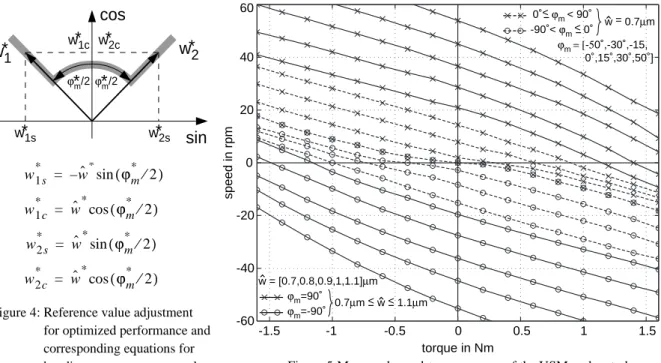
In [4] it is pointed out that an operation with a perfect-travelling wave is optimal for minimized losses caused by the friction interface. This conditions are obtained when the amplitudes are equal to a single value , representing the amplitude of the travelling bending wave, and the phase is kept to . Thus, variations of speed-torque curves should be performed by adjusting on one hand. But on the other hand the amplitude can not be decreased under a certain threshold due to tribological uncertainties caused e.g. by the surface roughness in case of small amplitudes. For variations of the speed-torque characteristic in this inherent deadzone the drive must be operated with a non-perfect travelling wave by adjusting the phase . As proposed in [6]
optimal torque utilization and minimized losses under consideration of the inherent amplitude threshold are obtained when establishing the following requirements for adjusting the travelling bending wave:
• In any operation mode the amplitudes of both standing waves should be equal by .
• In the high-speed/high-torque region the USM should be operated with a perfect travelling wave by adjusting and ensuring optimal drive performance.
Pu Pd t≥0ms
Pu Pd
ωs ωm
TM wˆ
1 wˆ , 2
ϕm ωR
wˆ
1 wˆ
, 2 wˆ
wˆ ϕm ±90°
wˆ wˆ
min
ϕm
-1.5 -1 -0.5 0 0.5 1 1.5
torque in Nm
speed in rpm
-60 -40 -20 0 20 40 60
ϕm=90˚
ϕm=-90˚ 0.7µm < w < 1.1µm
0˚< ϕm < 90˚
-90˚< ϕm < 0˚ w = 0.7µm ϕm = [-50˚,-30˚,-15, 0˚,15˚,30˚,50˚]
w = [0.7,0.8,0.9,1,1.1]µm
Figure 4: Reference value adjustment for optimized performance and corresponding equations for bending wave vector control.
sin cos
ϕm/2 ϕm/2
w
*
1cw
*
2sw
*
1sw
*
2cw *
2w *
1*
*
w1s* = –wˆ*sin(ϕm* ⁄2) w1c* = wˆ*cos(ϕm* ⁄2)
w2 s* = wˆ*sin(ϕm* ⁄2) w2c* = wˆ*cos(ϕm* ⁄2)
Figure 5:Measured speed-torque curves of the USM under study.
∆wˆ∗= wˆ1∗–wˆ2∗= 0 wˆ
min wˆ wˆ
≤ ≤ ma x ϕm = 90°
• In the low-speed/low-torque region the phase shift must be used for control and the wave´s amplitude should be constant avoiding the deadzone for torque generation.
Thus, only one of the regulating quantities has to be varied by the speed control. In order to generate the refer- ence values of the bending wave control in Fig. 2 a transformation from polar coordinates represented by regulating quantities and to cartesian coordinates with symmetrical distribution over both phases is performed as depicted in Fig. 4 by the grey trajectory and the corresponding equations.
For production of measured values, training the neural net offline, measurements have to be performed by the following way:
• Measurements must be performed with respect to the overall range of operation. Since the control of USM should be designed for speed variable drives, investigations of non-motory quadrants have to be considered.
• Choosing appropriate reference values of bending wave control by the scheme outlined before an almost even distribution of measured curves within the operating range must be obtained.
Under consideration of statements above the measured curves of the USM under study are depicted in Fig. 5.
While in the high-speed/high-torque range the amplitude is varied from to in steps of (solid lines), in the low-speed/low-torque region (dashed lines) the phase is adjusted to val-
ues controlling the amplitude above the threshold for an impeccable
operation. Torque and speed are limited to and to prevent destruction of USM.
3.2. Basis function network for approximation of inverse contact model
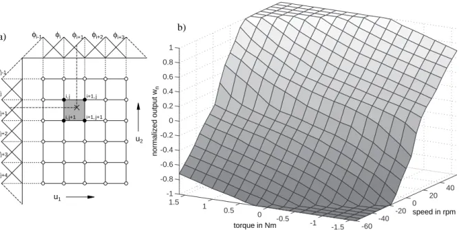
In order to generate the reference values of bending wave control from desired torque (calculated by the speed controller) under consideration of actual speed , the neural network applied for the inverse model serves for interpolation between the samples of a look-up table. Storing the information during the learning phase the output of a two-dimensional basis function network (BFN) is given by
, (6)
where is the continuous input vector of selected basis function and represents the weight of the acti- vated neuron. BFNs own properties as a well interpretation and convergence due to local training of the neuron layer as discussed in [9]. For approximation of the inverse model a two-dimensional network illustrated in Fig.
6a by piecewice linear, local basis functions (linear splines) is applied. For this special case a storage of matrix of neural weights is required only and a normalization of output is not necessary due to relation . Since four neurons are activated only, a fast and simple evaluation of (6) is achieved.
ϕm wˆ wˆ
= min
w1*,w2*
wˆ* ϕm*
wˆ
min = 0,7µm wˆ
ma x = 1,1µm
0,1µm ϕm
50
– °,–30°,–15°, ,0° 15°,30°,50°
[ ]
TM = 1,6Nm ωR = 60rpm
TM* ωR
-60 -40
-20 0
20 40
-1 -1.5 0 -0.5
1 0.5 1.5 -1 -0.8 -0.6 -0.4 -0.2 0 0.2 0.4 0.6 0.8 1
torque in Nm normalized output wn
speed in rpm
Figure 6: a) Neural network with piecewice linear basis function.
b) Two-dimensional BFN for approximation of inverse contact model generating the reference value of wave con- φi-1 φi φi+1 φi+2 φi+3
φj-1
φj
φj+1
φj+2
φj+3
φj+4
u1
u2 i+1,j+1
i,j+1 i,j i+1,j
a)
b)
y φij( )u wij
j
∑
i
∑
=
u φij wij
wij φij
i j
∑
= 1As mentioned before only one of the regulating quantities , are varied by the speed control. Thus, one BFN is sufficient for modelling the inverse characteristics. Therefore the transformation
(7)
is introduced. Normalized value represents the actual regulating quantity either for operations in the high- speed/high-torque or low-speed/low-torque region. Using (7) the net should be designed by:
1.Nonlinear transformation satisfying an even distribution with respect to the low-speed/low-torque range, since the no-load speed is roughly proportional to , see dashed curves in Fig. 5b.
2.Transparent parameter , introduced for scaling the two different operation modes in order to achieve an almost even slope of approximated inverse model within the common net for .
3.Deviation , caused by the difference between training (reference) data and net output , and size of neural layer, where a compromise between accuracy and amount of neurons is to be met.
The BFN designed for the inverse model is depicted in Fig. 6b. A layer of 41 times 17 neurons for the speed and torque input is used; parameter is set to . After learning a final fault of less than 1.5% within the whole input ranges is obtained. This accuracy is required, because of the large dependence on torque versus speed, see Fig. 5b. For learning the net offline the measured values of Fig. 5b are utilized. Since the density of measured values is very low, an interpolation between this samples is necessary in a first step. Therefore a numerical interpolator, which is more complex than the net, is used during the training phase. During learning random functions for inputs of torque and speed are applied in order to generate a stochastic even distribution of sample points used as training data. During the learning phase an adaptation of the BFN is achieved by
, (8)
with an appropriate learning rate [9], matrix of BF and the fault vector correcting the activated neurons.
For generating the regulating quantities and of the bending wave control the inverse transformation of (7) is performed. As illustrated in Fig. 6b the limitation of wave amplitude by is considered by .
For verification of the inverse contact model realized by the BFN the USM-drive is operated in open loop torque control. Measurements depicted in Fig. 7 prove the approach for compensation of nonlinear motor torque.
Thus, the so equipped USM-drive meets requirements for applications in the field of servo systems.
wˆ* ϕm*
wn
1–wnα wˆma x–wˆmin
--- w(ˆ –wˆmin)+wnα for wˆmin≤ ≤wˆ wˆma x, ϕm= 90°
wnα⋅sinϕm for wˆ wˆ
= min,–90°<ϕm<90°
wnα–1 wˆ
max wˆ – min
--- wˆ wˆ – min
( )–wnα for wˆ
min wˆ wˆ
≤ ≤ ma x, ϕm= –90°
=
wn ϕm sin
ϕm sin wnα
wn
∆wn wn ref, wn
wnα 0,4 ∆wn
∆wn = η(wn ref, –wn)Φ
η Φ ∆wn
wˆ* ϕm*
wˆ
max wn ≤1
-60 -40 -20 0 20 40 60
-1.5 -1 -0.5 0 0.5 1 1.5
speed in rpm
torque in Nm
measurements reference torque
limitation of operating range wmax, ϕm = 90˚
wmax, ϕm = -90˚
Figure 7: Verification of inverse model.
For verification of the designed BFN the USM-drive is operated in open loop torque control (see also Fig. 8), while the desired speed is regulated by a dc-machine otherwise applied for loading the USM-drive.
The input torque of BFN is adjusted
between in
steps of 0.5 Nm and compared to the measured torque within the maxi- mum range of the motor´s speed.
Besides scattered values around zero- speed, affected by the interpolation fault of the BFN, systematical devia- tions occur in case of high speed and torque due to the influence of temper- ature on USM´s speed-torque curves.
1,5Nm
– ≤TM* ≤1,5Nm
4. Speed control loop using inverse contact model by neural net
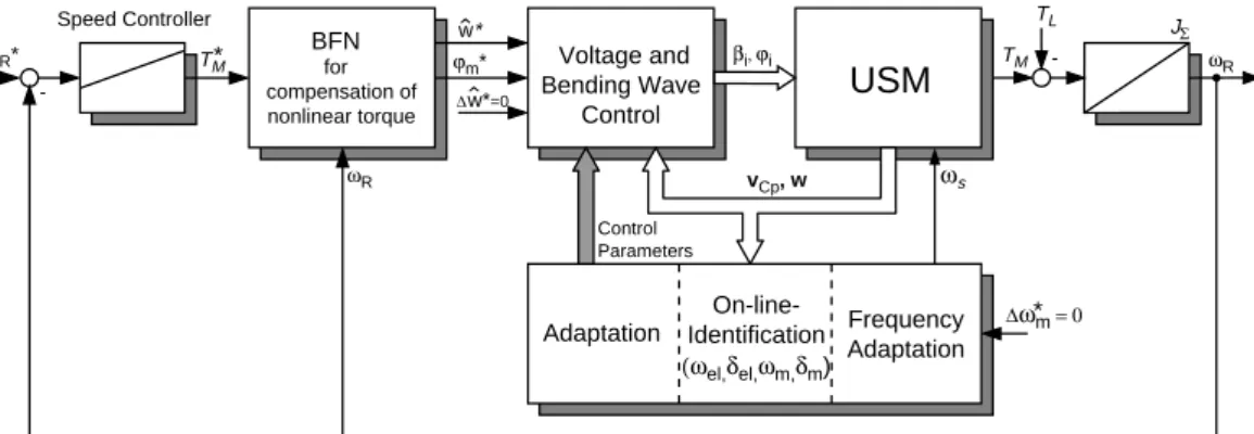
Since the reference values of the bending wave control are calculated from the desired torque value by the BFN under consideration of actual motor speed, the command behaviour of the new actuator approaches that of con- ventional drives. Designing the speed control proven schemes can be applied depending on the application. For the simple mechanical example of a one mass system a PI speed controller can be applied as illustrated in Fig. 8 by the overall scheme of the controlled USM-drive.
5. Conclusion
This paper proposes an inverse contact model for compensation of nonlinear torque generation of USMs. After a brief review of a simulation model for the overall drive system a two-phase vector control scheme for voltage and bending wave control is outlined. It is proved by the novel scheme that an operation at the mechanical resonance is feasible optimizing the drive´s performance remarkably. Remaining nonlinearity of the motor´s nonlinear torque generation is compensated by an inverse model calculating the optimized reference values of underlaid bending wave control. For this task a basis function neural network is applied, verified by measurements. By using a trans- formed regulating quantity one net output is used only for operations in the high-speed/high-torque as well as in the low-speed/low-torque region. By compensation of the nonlinearity the command behaviour of the USM approaches that of conventional drives and is thus attractive for applications in the field of servo systems.
Acknowledgement
The authors acknowledge gratefully the support of the German Research Council (DFG) for financing this USM-project. Thanks belong to the research department F2A/S of the Daimler Benz AG in Frankfurt for sup- porting the institute with travelling wave type USMs.
References
[1] T. Sashida, T. Kenjo: An introduction to ultrasonic motors. Clarendon Press - Oxford (1993).
[2] S. Furuya et al.: Load-adaptive frequency tracking control implementation of two-phase resonant inverter for ultrasonic motor. IEEE Trans. on Power Electronics, Vol. 7, No. 3, July 1992, pp. 542-550.
[3] J. Maas et al.: Simulation Model for Ultrasonic Motors powered by Resonant Converters. IAS´95, Orlando, Vol.
1, pp. 111-120, Oct. 1995.
[4] J. Maas, P. Ide, H. Grotstollen: Characteristics of Inverter-Fed Ultrasonic Motors – Optimization of Stator/
Rotor-Interface. 5th Int. Conference on New Actuators - ACTUATOR 96, Bremen, pp. 241-244, 1996.
[5] T. Senjyu et al.: Quick and Precise Position Control of Ultrasonic Motors with Two Control Inputs. PESC´95, Atlanta, pp. 415-420, June 1995.
[6] J. Maas, H. Grotstollen: Cascaded Control Scheme for Speed Variable Ultrasonic Drives. IAS´96, San Diego, Vol. 2, pp. 440-447, 1996.
[7] J. Maas, H. Grotstollen: Averaging Model for Inverter-Fed Ultrasonic Motors. PESC´97, St. Louis, Vol. 1, pp. 740-746, 1997.
[8] J. Maas, T. Schulte, H. Grotstollen: Optimized Drive Control for Inverter-Fed Ultrasonic Motors. IAS´97, New Orleans, Vol. 1, pp. 690-698, 1997.
[9] M. Brown, C. Harris: Neurofuzzy Adaptive Modelling and Control. Prentice Hall, 1994.
ϕm* w*
w*=0
∆
TM TL
-
JΣ ωR
vCp, w ωs
ωR TM
ωR* -
Speed Controller
Voltage and Bending Wave
Control
βi, ϕi
USM
On-line- Identification
Adaptation Frequency
Adaptation
∆ω*m = 0 (ωel,δel,ωm,δm)
Control Parameters
BFN for compensation of nonlinear torque
*
Figure 8: Overall scheme of speed controlled USM-drive using neural network for compensation of the motor´s nonlinearity.