Towards Integrated Variant Management in Global Software Engineering: An Experience Report
Christian Manz and Michael Stupperich Research and Development
Daimler AG, Germany
Email: {christian.c.manz, michael.stupperich}@daimler.com
Manfred Reichert
Institute of Databases and Information Systems University of Ulm, Germany
Email: manfred.reichert@uni-ulm.de
Abstract—In the automotive domain, customer demands and market constraints are progressively realized by elec- tric/electronic components and corresponding software. Variant traceability in SPL is crucial in the context of different tasks, like change impact analysis, especially in complex global software projects. In addition, traceability concepts must be extended by partly automated variant configuration mechanisms to handle restrictions and dependencies between variants. Such variant configuration mechanism helps to reduce complexity when con- figuring a valid variant and to establish an explicit documenta- tion of dependencies between components. However, integrated variant management has not been sufficiently addressed so far.
Especially, the increasing number of software variants requires an examination of traceable and configurable software variants over the software lifecycle. This paper emphasizes variant traceability achievements in a large global software engineering project, elaborates existing challenges, and evaluates an industrial usage of an integrated variant management based on experiences.
Keywords—software product line, integrated feature modeling, traceability.
I. INTRODUCTION
In the automotive domain, customer expectations (e.g., product individualization, product performance) have led to a continuously increasing number of product variants. Global commercialization of products and homologation constraints (e.g., due to market specific laws) constitute additional factors introducing product variability. In current practice, this product variability is usually enabled by electric/electronic components and corresponding software. Thereby, software product lines (SPL) are characterized by a planned and systematic reuse of software artifacts in different circumstances (e.g., different vehicles, and markets). Benefits of a SPL include improved quality results, reduced costs, and shorter time-to-market in respect to similar software products [1], [2].
The approach taken in a SPL differs from the traditional development of a standalone software product [1]. To handle common as well as variant specific software parts across a SPL constitutes a challenge in global software engineering projects.
While common parts are included in every product (e.g., every vehicle has an engine), variability describes different features of products (e.g., standard, sportive, classic).
To understand variability in a SPL, we analyzed a de- velopment process for an engine control unit and its em- bedded software system by Daimler Trucks. This process involves development phases like e.g., requirements engineer- ing, specification, design, implementation, integration, testing,
and calibration. Further, the development process comprises a number of abstraction layers (e.g., system and sub-system), and different artifact types (e.g., requirements, function models, test specifications, and regression tests or calibration parame- ters). In particular, this process is crucial for all core markets (Europe, NAFTA, Japan) to be able to react on respective market needs. This paper reports on experiences we gathered when extending the existing development process by Daimler Trucks with an integrated feature model. In turn, this inte- grated feature model considers the above mentioned phases, abstraction layers, and development artifacts. It further enables traceability and configuration of software variants and links, for example, all artifacts related to an emerging requirement through existing development phases for one specific software variant. Furthermore, an integrated feature model must handle the rising complexity introduced by software variants (e.g., conflicts resulting from the combination of excluding artifact).
The development process we analyzed allows for a detailed analysis as well as traceability of emerging requirements (e.g., planning, realization, costs). However, restrictions and dependencies between software artifacts as well as the creation of software variants constitute tacit knowledge. Through an ex- tension of our existing development process, in this context we expect a quality improvement in the software build process by a semi-automated variation point configuration in the artifacts.
Further, the interaction of the existing development process and the integrated feature model becomes essential. Major chal- lenges include the realization of an integrated feature model, the handling of its impact on the present development process, and the evolution of variability over time in combination with the existing development process. Emerging requirements lead to evolutionary changes and result in new artifact versions and software releases. Especially, the relationship of software releases and software variability will be evaluated.
Based on the experiences we gathered in global soft- ware engineering projects (cf. Section II) this paper discusses achievements and industrial challenges with respect to an integrated variant management of a global powertrain SPL at Daimler Trucks (cf. Sections III and IV). An evaluation of the extended development process is described in Section V.
Related work is discussed in Section VI. The paper concludes with a summary in Section VII.
II. GLOBALSOFTWAREENGINEERINGPROJECT
This section describes background information about the SPL we analyzed. Thereby, developing the powertrain of a
truck is becoming more and more an international project.
Especially in the automotive industry, the requirements re- alized by different markets are not identical, hence market- specific solutions become necessary. To match these local requirements with different markets, Daimler Trucks is present with different brands, including Mercedes-Benz, Freightliner, Western Star, and Mitsubishi FUSO. To develop these market- specific solutions, local development sites are crucial. Daimler Trucks established such development sites in Germany, the US, Japan, and Brazil. Nevertheless, Daimler Trucks establish a globally developed SPL to reuse common parts for all markets and brands. Overall, several teams from different sites collaborate within the same project to develop a SPL and realize different variants of an engine control unit. This SPL provides the basis for a number of software variants used in different markets for different trucks with different start of production schedules. Thereby, a harmonization and integration of diverse stakeholders must be realized regarding a coordinated cooperation among intercultural development teams. Therefore, Daimler Trucks established a common and globally approved development process for the engine control unit SPL. All requirements and emerging changes are realized by this common development process. In particular, traceable development and release planning are essential in such global software engineering projects. Through the rising complexity, relations and restrictions between software parts must be documented in an explicit manner.
III. ACHIEVEMENTS
Establishing an international development project consti- tutes a challenging task. As a prerequisite, a common de- velopment process must be introduced. In the automotive industry, usually, an iterative approach using multiple V-cycles is established. Based on such a common development process, all teams are able to plan and track the approval, realization, testing, and release of new requirements as well as the fixing of bugs. In particular, we have not only established this development process in respect to common software parts, but also for variant-specific parts. Thus, it is possible to manage the development of the common software parts in parallel with any market-specific variants. To ensure maintainability, bug fixing, and requirement traceability of such long-running global software projects, all requirements must pass a certified engineering process and be documented ( [3] for details).
Another challenge is to introduce a common configuration and revision control (like an application lifecycle management) in combination with the existing tool chain (e.g., MKS In- tegrity, Doors, Matlab/Simulink, TargetLink, INCA). This is used to manage the SPL as well as all related files. In this context, we can reuse commonly known variability techniques (e.g., model construction time, precompile time, compile time, post build [4]) to derive software variants. Different variability techniques are needed to meet variant-specific requirements (e.g., memory consumption, customization, development ef- fort) and implies different binding times. A further character- istic of the analyzed powertrain SPL is post build calibration.
By using different calibration parameters, it becomes possible to adapt the software to different vehicles post build. The major variability part in our project is bound in the calibration.
Overall, the worldwide distributed teams are able to de-
velop a common SPL. Different software variants can be derived and used for different markets. Nevertheless, com- plexity will be growing tremendously, when the number of variants increases. To tackle this challenge, we decide to extend our development process through an integrated feature model within a prototype. Also, we assume that manual variability configuration effort will further increase. We consider to substitute a manual variability configuration through a semi automated build process in combination with feature models.
IV. INDUSTRIALCHALLENGES
Integrated traceability is well-known for improving the maintenance of a software product, and many techniques exists in the context of traditional product development [5], [6] and SPL engineering [7]–[9]. The industrial challenges described in the following result from expert and engineer interviews at Daimler Trucks and are based on the experiences they gathered with product variants. The challenges emerged during a extension of the existing development process through an integrated feature model.
One challenge in our global software engineering project is the partly implicit variant configuration mechanism to handle restrictions and dependencies between variants. The documen- tation of restrictions and dependencies within different artifacts will be insufficient if the number of software product variants increases in future. As an illustrating example consider the following scenario. “If a new requirement emerges, a new function must be implemented for a special variant. Still, there exists several tracing information, e.g., requirement, relevant variant, design artifacts, code artifacts, test artifacts. Informa- tion concerning restrictions and dependencies like, e.g., func- tion A requires hardware platform B, test case D only usable in a specific market, are still documented, but not in an integrated and explicit form.” Especially increasing software complexity due to potentially rising number of software variants as well as associated restrictions and dependencies of software artifacts lead to a difficult configuration task of one software variant. We categorize the industrial challenges into two major challenges:
A. Challenge 1: Integrated Variant Configuration Based on Integrated Feature Model
Integrated Feature Modeling
Abstraction Layers
Responsibility
Requirements System Specification
System
Design Implementation Integration Testing Calibration
Development
B B B
B B B B
Feature & Artifact Relation
Calibration View
F5
F6 F7
F2 F3 F4
F1
Mandatory Optinal B = Binding TimeOr
Integrated Feature Model
F5
F6 F7
F2 F3 F4
F1 F1
F2 F3
Requirements View
F = Feature
I
II II
I I I I I I
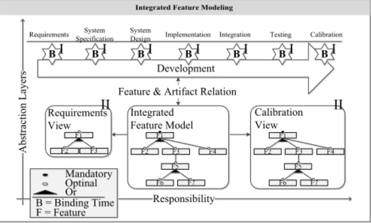
Fig. 1. Integrated Feature Modeling.
A common method to handle restrictions and relations between product characteristics is feature modeling [1]. Thus, feature modeling is a useful method to document tacit knowl- edge in an explicit manner. It helps to reduce the complexity to configure a valid variant and to establish an explicit documen- tation of dependencies between components. As mentioned in the introduction, an integrated variant management through an integrated feature model must consider several development phases, abstraction layers, and artifacts. Fig.1 illustrates a schematic representation of the existing development process (upper part) and the extension through an integrated feature model (lower part). Fig.1 is an abstract illustration, taking account to different development processes and variability techniques.
1) C1-I1 (Documentation of different binding times).
The time at which a configuration choice is made and a specific characteristic is selected, is called binding time. Fig.1 I illustrates common binding times in an embedded SPL. An integrated variant configuration has to treat different binding times as well as related artifact types. Different artifact types lead to different variance mechanisms (e.g., requirements annotation in contrast to preprocessor statements). As a result, integrated variant management has to be aware of different variance mechanisms and manage tool in- terfaces [4], [10].
2) C1-I2 (Integrated configuration of the build pro- cess).Documentation of all binding times is essential, but has to be supplemented by variation point config- uration. Thereby, a special software characteristic is selected, and variability can be controlled indepen- dently of the used mechanisms. Accordingly, inte- grated variant management needs to support different variance mechanisms. Thus, integrated configuration of an existing build process with all relevant tools is a further issue.
3) C1-I3 (External/Internal variability).Literature as- sumed commonly that variability is introduced only in the requirements artifacts. Therefore, feature mod- els are derived from requirements and linked with relevant artifacts in the development process. How- ever, additional variability may arise, typically from technical reasons, and has to be documented in the feature model. Pohl et al. and Rosenmüller describe this fact as “external and internal variability” [4], [11]. External variability comprises the context or configuration of a component and is normally a part of requirement definition. In contrast, internal vari- ability typically arises from technical reasons (e.g., different hardware platforms), and is documented im- plicitly in corresponding artifacts. The documentation of internal variability is a further issue.
4) C1-I4 (Differencing views). An integrated feature model in a large global embedded engineering project can easily become too complex [12]. Furthermore, not all features and associated artifacts are relevant for an individual engineer. As an example Fig.1 II illustrates two different views of an integrated feature model. As an additional issue, a view concept has to be realized.
5) C1-I5 (Artifact dependencies):In a global software
engineering project, dependencies between software artifacts have to be handled. In industrial projects, de- pendencies between artifacts are usually tacit knowl- edge or documented in an implicit form (e.g., code comments, environment variables, scripts). Feature models provide a technique to describe these depen- dencies in an explicit and standardized manner. Nev- ertheless, dependencies have to be known. Experts have to be incentivized to document tacit knowledge in feature models.
B. Challenge 2: Unify Change Management and Variant Con- figuration
Further development implies permanent changes in various development artifacts. In our projects, a predefined devel- opment process is used to structure emerging requirements.
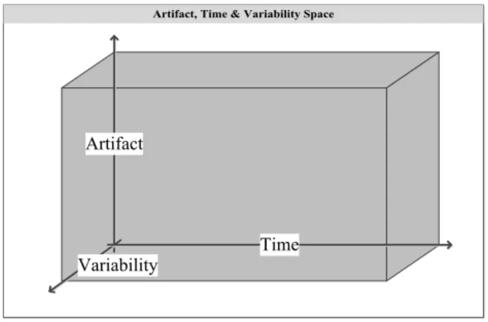
Release planning and understandable artifact evolution over time are important tasks. In case of a bug, for example, dependencies between releases can be reconstructed and fixed with improved quality. Fig.2 illustrates three development dimensions of a long-running SPL.Timeis the first dimension (X-axis in Fig.2), and considers the evolution of a SPL (e.g., revision control with versions and releases).Artifactis a further dimension (Y-axis in Fig.2), and includes all artifacts in the existing development project (e.g., process and repository).
Especially in a SPL variability (Z-axis in Fig.2) is an addi- tional dimension, and considers differences between software products (e.g., feature modeling).
Artifact, Time & Variability Space
Artifact
Variability Time
Fig. 2. Artifact, Time & Variability Space.
Techniques to handle each dimension are available. How- ever, techniques are available to conjunct two dimensions.
Change management, for example, combines the artifact and time dimensions. Furthermore, feature modeling in combi- nation with associated artifacts conjuncts the artifact and variability dimensions. In the following, we describe issues in case of a conjunction of all three dimensions.
1) C2-I1 (Variability changes). Product characteristics may change through the evolution over time. Corre- sponding features are, for example, added, removed, renamed, split, or merged. This evolution has to be considered in feature models. Evolution of features
has to be traceable, in particular to enable a high qualitative bug fixing.
2) C2-I2 (Artifact changes). Through the evolution over time, artifacts and their related variation points are added, removed, renamed, split, or merged, for example. This evolution has to be considered in arti- fact models and their corresponding variation points.
The evolution of artifacts and corresponding variation points in the variance dimension has to be regarded efficiently and traceable.
3) C2-I3 (Restrictions & Relations). Restrictions and relations may change over time, within artifacts and features as well as among artifacts and features. As an example, a feature can be optional in the first release and become mandatory in a further release, or an artifact may related with one feature only and get related with several features over time. A technique to document this evolution is needed.
V. EVALUATION OF ANINTEGRATEDVARIANT
MANAGEMENT IN ANINDUSTRIALPROJECT
To analyze the industrial usage of an integrated feature model, we extended the existing SPL. We focused on the conjunction of the existing development process and an in- tegrated feature model. For this purpose, we defined a stan- dardized and extended integrated feature model. Moreover, we extracted existing variation points from different artifact types via scripts. In addition, we inserted relations and restrictions between features, artifacts, and variation points.
With regard to the first challenge (cf. Section IV-A), we were able to achieve a satisfactory result. To address different binding times (C1-I1), we realized several artifact-specific connectors between the feature model and artifact types.
Because of different artifact types, variability techniques, and different tools, this was a time-consuming challenge. Further, variability mechanisms had to be identified as well. We solved this challenge with an explicit characterization of variability mechanisms in the artifacts and associated connectors. In a real SPL, this expensive approach is not reasonable. The connector concept also fulfills C1-I2, and enables configuration of available variation points. To resolve issues C1-I3 and C1-I5, implicit expert knowledge was needed. To accelerate this time-consuming task in future, we decided to extend the existing development process by additional process steps.
Each variability has to be documented in the feature model, and each variation point has to be linked with the feature model. This implies to document not only actual binding times, but also realized variability with a binding time in further development (e.g., if a variation point is introduced, the variability has to be documented even though the final characteristic is unknown). Further, we realized user-specific views (C1-I4) by development phase and abstraction specific feature models within a hierarchical feature model. User- specific views in feature models are not supported in the used feature modeling tool yet.
With regard to the second challenge (cf. Section IV-B), we achieved dissatisfying results. This challenge illustrates the complexity of variance evolution over time. We derived two alternative approaches to solve the challenge to combine change management and variant configuration management.
Initially, we handled the integrated feature model as a normal artifact in the existing change management tool, and as a normal subject in revision control. Evolutionary changes in the integrated feature model were reconstructable only through version comparison of the integrated feature model. Trac- ing information about the renaming, splitting, or merging of features (issue C2-I1) was lost, for example. Additionally, a huge effort was needed to show the variant evolution of a specific artifact. If, for example, an individual artifact changes variability characteristics (issue C2-I2) over time, a complex comparison technique was needed to visualize variant evolu- tion. Evolution in restrictions and relations (issue C2-I3) can be handled in different integrated feature model versions but were not traceable. Changes in restrictions and relations could only be reconstructed though version comparison of integrated feature models.
In the second approach, we realized only one version of an integrated feature model, and tried to document the evolution over time within this integrated feature model. To document variability changes over time (issue C2-I1), we added addi- tional release features to the integrated feature model, and added relations and restrictions to the according features. We were able to document new or deleted features within evolution over time. Split, renamed, or merged features could not be traced. To document artifact changes over time (issue C2-I2), further meta information was added to the artifact models.
Each artifact implied meta data with relevant version infor- mation (e.g., included versions). In addition, this information was related to the newly defined release features. We were able to document relations between artifact versions, releases and features. As a drawback of our solution, the feature and artifact models became huge and complex. We have implemented algorithms to find each artifact in the revision control system.
Each version in the revision control system had to be analysed concerning available artifacts. We stored this information in so called150% artifact models. The name indicates an redundant information storage. Additionally, all version information had to be synchronized with existing version control tools. Manual changes were error-prone and needed to be substituted by specialized scripts. We were not able to document restrictions and relations evolution (issue C2-I3) with the existing feature modeling tool. Further research is required, to resolve this issue.
All in all, we recognized the complexity arising from variant configuration through an integrated feature model and evolution over time.
VI. RELATEDWORK
In classical product development, the traceability challenge has already been discussed in several papers. Asuncion et al. used a central data storage tool, like a database, as an information provider [6]. Arkley and Riddle establishedTrace- able Development Contracts (TDC) to link different artifacts between the problem and the solution space. They treated sim- ilar problems in industrial projects, and illustrated the urgent need for traceability in the product life cycle. These approach do not consider product variants, but focus predominantly on requirement traceability. However, in this paper, we intend to enable traceability of each artifact [5].
A lot of research has been done in the area of SPL. Reiser
introduced the structure of a product subline (subline). He recognized the need to put different sublines into relation.
To hierarchically organize sublines, he introduced multi-level feature models. He formalized relations between feature mod- els, and used them to manage complex products in a huge automotive company. We used the approach of Reiser as a basis for our integrated feature model and created an individual feature model for each development phase, and put them into a relation [13].
Anquetil et al. describe problems, analyse existing require- ments traceability tools, and recognize the lack of SPL support.
Also academic approaches are listed but none provides a clear and comprehensive view of trace links in a SPL. The authors define four traceability dimensions in SPL, and describe ATF (AMPLE traceability framework), a model-driven traceability framework, and its realization. In particular, the four traceabil- ity dimensions “refinement”, “similarity”, “variability”, and
“versioning” are inspiring for an integrated feature model. In our evaluation, we addressed “refinement”, “similarity”, and
“variability” with our integrated feature model. Anquetil et al.
describe also increasing complexity aspects considering ver- sioning requirements. They insert additional tracing links and develop several algorithms to handle evolution over time. To handle the versioning dimension, we also realized algorithms to reduce complexity. [7].
Hallerbach et al. describe Provop, an approach to handle variability in business processes. Process contexts control the configuration of a particular process variant. Variability in business processes differs from product variability, which con- tributed the scope of this paper. Dependencies between product variability and process variability have to be investigated in further research [14].
VII. CONCLUSION
A globally developed SPL realizes benefits like improved quality, reduced costs, and market-specific adaptions. The ex- isting development process allows for structured and traceable evolution over time for common software parts as well as variant specific parts. Nevertheless, variant specific information like realization, dependencies, or restrictions between software artifacts are partly tacit knowledge. Feature modeling is a technique to document this knowledge in an explicit manner.
Especially in a global SPL, an integrated feature modeling technique is a further advantage. We implemented a prototypi- cal realization of an integrated feature model, and observed its impact on the existing development process. Feature definition, variation point documentation, and linking, as well as relation and dependency documentation have to be common tasks in the existing development process. Currently, an insufficient tool integration is a major challenge to an integrated fea- ture model. Different artifact types and involved variability techniques require specialized connectors between the feature model and artifacts. In addition, the configuration of different variability techniques are complex. For integrated industrial usage, an artifact-independent standardized variability interface for existing tools is needed. The detection of variable objects in artifacts is a major challenge. As a result, a quality-improved build process through feature selection with an explicit doc- umentation of dependencies and restrictions can be achieved.
Invalid configuration of variants can be successfully avoided.
In particular, evolution over time in combination with com- mon feature modeling techniques require further investigation.
Tracing of software variability evolution results in complex feature models or loss of information. This illustrates the complexity among variability and evolution over time. Further research has to be done to conjunct product evolution over time and integrated feature models (variability).
ACKNOWLEDGMENT
This work is part of the “Software Platform Embedded Systems 2020 XT” (SPES XT) project. SPES XT is supported by the German Federal Ministry for Education and Research (BMBF) by 01IS12005.
REFERENCES
[1] K. Pohl, G. Böckle, and F. Linden,Software Product Line Engineering:
Foundations, Principles, and Techniques. Berlin: Springer, 2005.
[2] S. Thiel and A. Hein, “Modeling and using product line variability in automotive systems,”IEEE Software, vol. 19, no. 4, pp. 66–72, 2002.
[3] M. Stupperich and S. Schneider, “Process-focused lessons learned from a multi-site development project at daimler trucks,” inProc 6th Int Conf on Global Software Engineering (ICGSE), IEEE, Ed., 2011, pp. 141–
145.
[4] M. Rosenmüller, N. Siegmund, T. Thüm, and G. Saake, “Multi- dimensional variability modeling,” in Proc 5th Int Workshop on Vari- ability Modelling of Software-intensive Systems (VaMoS). New York:
ACM, 2011, pp. 11–20.
[5] P. Arkley and S. Riddle, “Overcoming the traceability benefit problem,”
in13th IEEE Int Conf on Requirements Engineering (RE). IEEE, 2005, pp. 385–389.
[6] H. U. Asuncion, F. François, and R. N. Taylor, “An end-to-end industrial software traceability tool,” inProc 6th Joint Europ Soft Eng Conf and ACM SIGSOFT Symp on the Found of Soft Eng (ESEC/FSE), 2007, pp.
115–124.
[7] N. Anquetil, U. Kulesza, R. Mitschke, A. Moreira, J.-C. Royer, A. Rummler, and A. Sousa, “A model-driven traceability framework for software product lines,”Software & Systems Modeling, vol. 9, no. 4, pp. 427–451, 2010.
[8] K. Berg, J. Bishop, and D. Muthig, “Tracing software product line vari- ability – from problem to solution space,” inProc Annual Research Conf of the South African institute of Computer Scientists and Information Technologists on IT research in developing countries (SAICSIT), 2005, pp. 182–191.
[9] J. Bayer and T. Widen, “Introducing traceability to product lines,” in Proc 4th Int Workshop on Product Family Engineering (PFE), E. S.
Institute, Ed., Bilbao and Spain, 2001, pp. 399–406.
[10] J. Bosch, G. Florijn, D. Greefhorst, J. Kuusela, H. Obbink, and K. Pohl,
“Variability issues in software product lines,” inProc 4th Int Workshop on Product Family Engineering (PFE), E. S. Institute, Ed., Bilbao and Spain, 2001, pp. 11–19.
[11] K. Pohl and A. Metzger, “Variabilitätsmanagement in software- produktlinien,” in Soft Eng 2008, ser. LNI, vol. 121. GI, 2008, pp.
28–41.
[12] M. Rosenmüller, “Towards flexible feature composition: Static and dynamic binding in software product lines,” Ph.D. dissertation, Otto- von-Guericke-Universität, Magdeburg, 2011.
[13] M.-O. Reiser, “Managing complex variability in automotive software product lines with subscoping and configuration links,” Ph.D. disserta- tion, TU Berlin, Berlin, 2008.
[14] A. Hallerbach, T. Bauer, and M. Reichert, “Capturing variability in business process models: The provop approach,”Journal of Software Maintenance and Evolution: Research and Practice, vol. 22, no. 6-7, pp. 519–546, 2010.