MBT and SRF
Regenerative Thermal Oxidation in the Cement Industry
– Technology and Operation –
Thomas Binninger and Kai Schulze
1. The cement industry ...417
2. How cement is made ...418
3. The use of alternative fuels and raw materials ...419
4. Emissions in the cement industry ...421
5. The regenerative thermal oxidation system ...422
6. Wopfinger Zement ...426
7. Outlook...428
8. References ...428
1. The cement industry
The cement industry plays a pivotal role in meeting society’s needs for housing and infrastructure. Cement is one of the most important and widely used commodities in the world and is therefore a key ingredient of economic development. Current world production of cement is well above 4,500 million tons per year and growing.
USA 1.8 %
India 5.9 %
China 51.3 % Japan 1.3 %
Asia (excl. China, Japan, India) 21.7 %
Africa 4.7 % America (excl. USA) 4.7 %
CIS 2.8 %
Europe (excl. CEMBUREAU) 0.1 % CEMBUREAU 5.4 % Oceania 0.3 %
Figure 1: World Cement Production 2015, by region and main countries
Source: CEMBUREAU
MBT and SRF
Cement is the key ingredient of concrete, which is used to build offices, factories, homes, schools, hospitals and roads, as well as our underground water and drainage pipes, bricks and blocks, and the mortar that bonds them together. None of these things could be built without cement. There is currently no other material that can replace cement or concrete in terms of effectiveness, price and performance for most purposes.
Not surprisingly there is a strong link between economic growth and the increase of cement production per capita.
While the cement industry is currently undergoing major consolidation, an example would be the merger between HOLCIM and Lafarge to form the largest cement produ- cer in the world with plants around the globe, there are still many smaller companies operating with only one or a few plants in local markets.
Today, the challenge for the cement industry is to balance a growing demand for cement with the need to forge a more sustainable cement industry.
2. How cement is made
Ordinary Portland cement is made by grinding a mixture of clinker and gypsum into a fine powder. Clinker is produced in a rotary kiln using raw materials like limestone, clay and silica in specific quantities. A cement plant comprises of raw material pre- paration and storage, raw mill, preheater with calciner, rotary kiln and clinker cooler.
Baghouse
Coal Mill Stack
Limestone Train
StorageCoal
Coal Mill
StackKiln
Conditioning Tower
Baghouse
Baghouse ID Fan
Kiln ID Fan Return Dust
Calciner
Grate Cooler Raw Mill
ID Fan Preheater Tower
Homo and Kiln Feed Silos
Roller Mill Heat Exchange Clinker
Silos Return Dust Flyash, Limestone and
Gypsum Silos
Finishing Mill
Cement Silos and Distribution
Cooler Stack Cooler Vent Fan Excess Air Filter
Additive Silos Preblend
Dome Hammermill
Crusher
Local Clay Quarry
Figure 2: Cement plant flow chart
Source: www.chemical-engineeringinfo.blogspot.co.at
MBT and SRF
Raw materials are being fed to a preheater tower, where they are heated using hot gases coming from the rotary kiln.
Finally the clinker is then ground in cement mills and stored in silos, before being shipped and used. Cement must conform to the strict specifications to meet standards set for it.
Figure 3:
Clinker (left) and cement
Source: www.nachi.org
The production of cement plants is typically measured in tons per day. Plants in Europe are commonly between 1,500 and 3,500 t/d. Larger plants in other areas of the world operate at 10 to 12,000 t/d. Waste gas volumes can be several hundred thousands of cubic meters per hour and contain a certain amount of dust.
Cement production is energy-intensive: It accounts for around 5 percent of global anthropogenic emissions of carbon dioxide, and affects a wide range of sustainability issues, including climate change and emissions to air.
A modern cement plant consumes between 3,000 to 4,500 MJ/t of clinker produced, depending on the raw materials and the process used.
3. The use of alternative fuels and raw materials
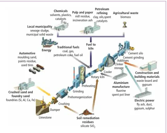
Since the mid-1980s, alternative raw materials and fuels derived mainly from industrial sources have been beneficially utilized in the cement industry. Cement kilns make full use of both the calorific and the mineral content of alternative materials. Fossil fuels such as coal or crude oil are substituted by combustible materials, which would otherwise need to be landfilled or incinerated in specialized facilities.
Cement plants are uniquely suited for using secondary materials: Kilns operate at high temperatures, between 2,500 °C in the flame of the main burner and 1,100 °C in the kiln inlet. Residence time of combustion gases in the kiln in excess of 4 seconds, providing ideal conditions for complete destruction of harmful constituents.
Most modern plants also have a calciner, where 50 to 60 percent of the thermal energy is introduced to drive the CO2 from the limestone at temperatures of around 850 °C.
These calciners again are normally designed with a residence time of 3 to 5 seconds.
MBT and SRF
Figure 4: Examples of feeding alternative fuels and raw materials
Source: CEMBUREAU
Chemicals solvents, plastics,
catalysts
Pulp and paper mill residue, incineration ash
Petroleum refining clay, oils,spent
catalysts
Agricultural waste biomass
Construction and building materials waste board and
gypsum
Electric power fly ash, dust, gypsum, sulphur Aluminium
manufacture fluorine spent pot liner
Soil remediation residues silicate SiO2 Local municipality
sewage sludge, municipal solid waste
Energy Automotive moulding sand,
paints residue, used tires
Fuel to Traditional fuels kiln
coal, gas, petroleum coke, fuel oil
Crushed sand and foundry sand foundries (Si, Al, Ca, Fe)
Limestone Dumper
Crushing
Prehomogenization Grinding
Preheating
Cement silo Cement grinding Additives Clinker storage Cooler Rotary kiln
Alternative fuel 1,000 t
MJ/kg
per year
Waste tyres 217 28
Waste oil 52 26
Fractions of industrial and commercial waste:
Pulp, paper and cardboard 92 5
Plastics 665 23
Packaging – –
Wastes from the textile industry – –
Others 1,138 21
Meat and bone meal and animal fat 151 18 Mixed fractions of municipal waste 308 16
Waste wood 3 13
Solvents 96 23
Fuller‘s earth – –
Sewage sludge 348 3
Others, such as: Oil sludge or 60 11 organic distillation residues
Source: VDZ: Environmental Data of the German Cement Industry. 2014
Table 1:
Used quantities and average calorific value of alternative fuels in 2014
MBT and SRF
The process takes place under oxidizing conditions with good mixing. Waste materials in the kiln are in contact with a large flow of alkaline materials that neutralize potential acid off-gases from combustion. Any inorganic mineral residues from combustion including most heavy metals are trapped in the clinker.
The German cement industry has managed to replace more than sixty percent of their primary with secondary fuels. In 2014 they utilized more than three million tons of a wide variety of different alternative fuels, Table 1.
In addition, plants also have been using suitable secondary raw materials as substitutes.
The types of waste materials used as raw materials have to be such, that the performance or characteristics of the cement or concrete are not changed. High levels of some minor components can affect cement performance, and the manufacturer needs to take care that specific thresholds are not exceeded. [3]
To provide some perspective: The German cement industry produces about 35 million tons of clinker per year, using roughly 50 million tons of raw materials. Currently about 16 percent of those raw materials are replaced by secondary materials. [6]
A good example is sewage sludge, a material which previously was dumped or used in agriculture. However, sewage sludge can also be used as both an alternative fuel and raw material in a cement plant. One plant in the Netherlands uses about 80,000 tons of dried sewage sludge annually in the kiln with a capacity of 865,000 tons of clinker per year. [2]
It should be noted that such practice, while wide spread throughout Western Europe, is still catching on in other parts of the world, where availability or permitting can be issues.
4. Emissions in the cement industry
Gaseous emissions from the kiln system released to the atmosphere are the primary environmental concern in cement manufacture today. CO2, a major greenhouse gas, is released in considerable quantities. The majority of it stems from the calcination of limestone, which is the main ingredient in clinker, from which cement is made. Other regulated gaseous emissions include NOx, SO2, VOCs, CO and NH3, which can be emitted from cement plants in significant quantities.
One of the peculiarities of the cement process is that there are process related emissions as well as those coming from the raw materials used.
Cement clinker is formed at high temperatures in a rotary kiln. Consequently signifi- cant amounts of thermal NOx are generated in the process and need to be treated, for example with an SNCR system.
Some primary raw materials contain small quantities of hydrocarbons, which volatilize in the upper stages of the preheater and are emitted with the off gas. The use of certain types of secondary materials can increase these emissions.
Since the use of secondary fuels is wide spread, cement plants are subject to regulati- ons similar to those for waste incinerators. Certain important exceptions are however allowed, since parts of the emissions are derived from the use of raw materials, Table 2.
MBT and SRF
The cement industry has had a long history of adapting plant operations to new and modified environmental rules. Significant regulatory transitions are currently being im- plemented in the industry, in the US and Europe particularly. The revised 17. BimSchV, [1], is a recent example. It imposes strict emission limits, which cannot always be met with the existing equipment in a cement plant.
unit Cement Plants, Waste Co-Incinerators Incinerators
Hg mg/Nm3 0.03 *** 0.03
TOC mg/Nm3 10 *** 10
CO mg/Nm3 50 *** 50
HCl mg/Nm3 10 10
HF mg/Nm3 1 1
D/F (TE) ng/Nm3 0.1 0.1
NH3 **** mg/Nm3 30 *** 10
NOx * mg/Nm3 200 150
SOx ** mg/Nm3 50 *** 50
Standard conditions, 10 % O2, dry
* NO2 basis
** SO2 basis
*** raw material derived emissions can be exempt
**** with SNCR system
Table 2:
Emission limits for co-incineration of waste material
Source: 17. BImSchV: Siebzehnte Ver- ordnung zur Durchführung des Bundes- Immissionsschutzgesetzes (Verordnung über die Verbrennung und die Mitver- brennung von Abfällen), 02.05.2013
Environmental regulations have grown in importance and are today a major factor in the operation of plants, just like for example maintenance. Non-compliance does result in costly production losses.
5. The regenerative thermal oxidation system
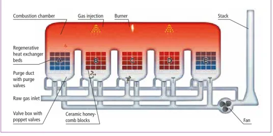
Regenerative thermal oxidizers treat waste gases from many industrial processes. The basic operating principle of the RTO consists of passing a hot gas stream over a heat sink material, ceramic honeycombs, in one direction and recovering that heat by pas- sing a cold gas stream through that same material once the direction of flow has been reversed. RTO can reach very high thermal efficiencies and are therefore widely used in pollution control.
The RTO consists of the following major components:
• Main fan,
• Inlet and outlet ducts with valves,
• Reactor, consisting of heat exchanger and combustion chamber,
• Burner system.
On large RTOs the main fan is typically located downstream of the RTO and is designed to convey the waste gases through the RTO and into the stack. A fresh air damper can be installed for start-up of the system and protection of the fan.
MBT and SRF
Inlet, raw gas, and outlet, clean gas, ducts are below the RTO and connected to cones leading up to the ceramic heat exchangers. Large, pneumatically operated poppet valves are opening and closing in sequence to control the gas flow in and out of the system.
The poppet valves are especially designed for RTO applications. They are robust, reliable and are available as single-sealing poppet valves with or without seal air depending on the specific requirements.
Figure 5: Components of the RTO
Raw gas inlet
Fan Valve box with
poppet valves Regenerative heat exchanger beds
Ceramic honey- comb blocks
Combustion chamber Gas injection Burner
Purge duct with purge valves
Stack
Figure 6: System overview of the RTO Figure 7: Regenerative system
MBT and SRF
The waste gas is directed through a ceramic heat exchanger bed. Depending on the design gas flow through the RTO, there can be several heat exchanger beds in longi- tudinal direction.
On its way through the heat exchanger the gases are heated up and reach a temperature that is close to the one in the combustion chamber, which is above the heat exchanger beds and connects all of them. The hot clean gas releases thermal energy as it passes through another ceramic heat exchanger bed on its way out of the RTO. This energy is regenerated, once the direction of flow switches again.
The heat exchangers and the combustion chamber are referred to as the reactor. The heat exchangers function as heat storage and minimize the system’s demand for energy, due to their ability to store the energy of the outgoing gas. In the combustion chamber, the pollutants are oxidized at temperatures between 800 and 1,000 ˚C and, in the case of VOC, converted to water vapour and carbon dioxide. The cleaned gas leaves the RTO through the clean gas duct.
The heat exchanger elements are especially resistant to chemical, thermal and mecha- nical influences due to the usage of high quality materials, which are especially selected and manufactured for the intended use. Linear flow of gas through media helps prevent particle deposition and subsequent obstruction.
Insulation protects the reactor walls from high combustion chamber temperatures and, at the same time, minimizes the radiation losses of the system. The internal insulation is designed for temperatures up to 1.000 °C and is also available as solid refractory lining, if additional protection is desired.
Since the lower end of the ceramic heat exchanger has the lowest temperatures, certain substances could condensate there. Condensing substances do not only reduce the cleaning efficiency of the RTO, but can cause deposits that may lead to corrosion. In order to protect the system from condensing substances, and extend its useful life, the raw gas can be preheated before it enters into the system.
Organic dust or aerosols may cause deposits on the ceramic heat exchangers resulting in rising pressure drop and a decrease in overall operating efficiency. In order to clean the heat exchanger and restore the original characteristics of the system, a simple bake-out is usually all that is necessary. Organic deposits removed during bake-out are processed through the combustion chamber, where any unburned hydrocarbons are destroyed.
Inorganic deposits on the heat exchanger beds can increase the system‘s pressure drop and cause a decrease in operation efficiency. Inorganic deposits can be removed from the heat exchanger beds with compressed air or washing with water.
The combustion chamber is equipped with a burner system for different gaseous fuels.
It consists of burner, gas and air system, as well as the combustion air fan and a burner management system. All components are installed in a protected area. The system may also be operated with a combination of liquid and gaseous fuels by using a multifuel burner. For higher fuel economy, it is recommended that a direct fuel injection system be installed along with the burner system. Fuel consumption and NOx generation can be further minimized with this option.
MBT and SRF
Fuel consumption is also reduced by optimizing the amount of combustibles in the waste gas. If concentrations are high enough, the RTO will not require additional primary fuel at all.
Figure 8:
Ceramic heat exchangers Large RTOs, like the ones used in the cement industry, are custom designed to meet the specific requirements. Their size is matched to the actual gas flows at the plants.
The cleaning efficiencies are tailored to the requirements of the plant.
Experience is a valuable tool and a major factor for success in designing emission con- trol systems. In addition, CFD (computational fluid dynamic) simulations as well as real-time dynamic calculations have taken up a leading role in reaching the optimum regarding cleaning efficieny and power consumption.
Figure 9:
RTO System
Based on the vast experience in cleaning waste gas streams from a wide variety of industries, CTP developped a comprehensive portfolio of systems for the cement in- dustry. The unique characteristic is the flexibillty to upgrade the systems and extend
MBT and SRF
their ability to reduce emission further and allow clients to keep step with changing environmental regulations. An RTO, for example, is well suited to reduce CO and TOC, but does usually not reduce NOx emissions. The system can be upgraded with an SNCR system to allow for additional NOx reduction. If at some point that should not be sufficient anymore, an SCR module can be integrated to improve performance.
Thermal Integrated Catalytic
CO/TOC RTO RCO
NH3 RTO + SCR
NOx RTO + SNCR SCR
Table 3:
System overview
This portfolio allows for a reduction in capital investement, while providing the upward comaptability. Future needs can be met in the same system.
6. Wopfinger Zement
Wopfinger Baustoffindustrie GmbH is an Austrian company, which operates a cement plant close to Vienna. The plant is located in a valley and odor emissions, derived from the clay, had been an issue for many years. The owner had previously tried out several different technologies to eliminate the odor. The RTO was also tested at the plant for two months, using a pilot unit. The results were positive and confirmed that the RTO was reducing odor, carbon monoxide and total organic carbon emissions and was suitable for operation in a cement plant.
Figure 10:
RTO at Wopfinger Zement
Source: Wopfinger Baustoffindustrie GmbH
The system is an end-of-pipe-solution, which does not affect the upstream process and allows for cleaning all waste gas streams coming from the plant, including waste gas from raw mill, two paper reject driers and the kiln gas bypass.
MBT and SRF Figure 11: Flowsheet Wopfinger RTO System
Because of the outstanding reduction rates provided by the RTO, Wopfinger gained new flexibility using secondary fuels and raw materials containing organic components, which couldn’t have been used before. These materials significantly increased CO and TOC concentrations in the raw gas entering the RTO. Despite of this increase, overall stack emissions have decreased significantly. The RTO provides an abatement rate of CO and organic compounds of about 99 percent. Odor emissions from the plant have disappeared alltogether.
However, the increase in concentrations also allows the RTO to operate in autother- mal mode, which means that the RTO does not require any primary fuel, if raw gas concentrations can be maintained above 5,000 mgCO/Nm3 in the entering raw gas. This considerably reduces operating cost.
The RTO at Wopfinger is designed for 218,000 Nm3/h of raw gas. It has a hot bypass, which provides the flexibility to process gas streams that are highly variable in concen- tration, as well as to tolerate upsets in the process without overheating.
A unique and novel feature of the Wopfinger RTO is the integration of an SNCR system to reduce NOx emissions in the combustion chamber. The SNCR systems consists of se- veral nozzles, which spray an aquaeous ammonia solution into the combustion chamber, where temperatures are condusive for the non-catalytic reduction of NOx. Reduction rates of more than 50 percent have been reached. The plant has another SNCR system in the calciner, which now works together with the second SNCR system in the RTO.
Bypass Q = 20,000 Nm3/h T = 175 °C
Driers
Q = 50,000 Nm3/h T = 140 °C Raw mill
Q = 110,000 Nm3/h T = 180 °C
Stack
RTO Fan Bag filter Fan
Wopfinger Baustoffindustrie GmbH Waldegg, Austria
MBT and SRF
Depending on the raw gas inlet concentrations, the temperature difference across the RTO is around 40 to 60 °C and the pressure difference about 35 mbar.
The RTO has been operating for almost five years with very high availabilities. One shutdown, which coincides with the yearly shutdown of the cement plant, has proven to be sufficient.
There are very few wear parts in the RTO. One item that requires attention are the sealings under the poppet valves. These valves perform about 300,000 cycles per year and the sealings should be carefully maintained, since they impact the cleaning effici- ency of the RTO. The ceramic heat exchangers however do not wear and are expected to last many more years.
The largest single maintenance item is cleaning dust deposits from the ceramic blocks.
The blocks can be cleaned in-situ, using compressed air or dry ice, which removes dust deposits from inside the honeycombs. The cleaning is done during the yearly plant shutdown and takes a few days.
7. Outlook
The RTO has proven to be a reliable and robust piece equipment in the cement industry.
It provides the required emission reduction and creates opportunities for using other alternative materials.
CTP has devlopped solutions around the standard RTO, which allow it to grow with demands, be it additional NOx control or highest reduction rates.
With the increasing pressure to reduce emissions, we can expect to see more RTOs in the cement industry in the future.
8. References
[1] 17. BImSchV: Siebzehnte Verordnung zur Durchführung des Bundes-Immissionsschutzgesetzes (Verordnung über die Verbrennung und die Mitverbrennung von Abfällen), 02.05.2013 [2] CEMBUREAU: Sustainable cement production, Co-processing of alternative fuels and raw ma-
terials in the European cement industry. January 2009
[3] CSI: Guidelines for Co-Processing Fuels and Raw Materials in Cement Manufacturing. Version 2.0, 2014
[4] Philipp, G.: Regenerative Thermal Oxidation (RTO) with integrated NOx reduction. ZKG 11, 2013
[5] VDZ: Environmental Data of the German Cement Industry. 2014
[6] Wuppertal Institut für Klima, Umwelt, Energie GmbH: Rohstoffversorgung und Ressourcen- produktivität in der deutschen Zementindustrie. Oktober 2015
Bibliografische Information der Deutschen Nationalbibliothek Die Deutsche Nationalbibliothek verzeichnet diese Publikation in der Deutschen Nationalbibliografie; detaillierte bibliografische Daten sind im Internet über http://dnb.dnb.de abrufbar
Thomé-Kozmiensky, K. J.; Thiel, S. (Eds.): Waste Management, Volume 6 – Waste-to-Energy –
ISBN 978-3-944310-29-9 TK Verlag Karl Thomé-Kozmiensky
Copyright: Professor Dr.-Ing. habil. Dr. h. c. Karl J. Thomé-Kozmiensky All rights reserved
Publisher: TK Verlag Karl Thomé-Kozmiensky • Neuruppin 2016
Editorial office: Professor Dr.-Ing. habil. Dr. h. c. Karl J. Thomé-Kozmiensky,
Dr.-Ing. Stephanie Thiel, M. Sc. Elisabeth Thomé-Kozmiensky, Janin Burbott-Seidel und Claudia Naumann-Deppe
Layout: Sandra Peters, Anne Kuhlo, Janin Burbott-Seidel, Claudia Naumann-Deppe, Ginette Teske, Gabi Spiegel und Cordula Müller
Printing: Universal Medien GmbH, Munich
This work is protected by copyright. The rights founded by this, particularly those of translation, reprinting, lecturing, extraction of illustrations and tables, broadcasting, micro- filming or reproduction by other means and storing in a retrieval system, remain reserved, even for exploitation only of excerpts. Reproduction of this work or of part of this work, also in individual cases, is only permissible within the limits of the legal provisions of the copyright law of the Federal Republic of Germany from 9 September 1965 in the currently valid revision. There is a fundamental duty to pay for this. Infringements are subject to the penal provisions of the copyright law.
The repeating of commonly used names, trade names, goods descriptions etc. in this work does not permit, even without specific mention, the assumption that such names are to be considered free under the terms of the law concerning goods descriptions and trade mark protection and can thus be used by anyone.
Should reference be made in this work, directly or indirectly, to laws, regulations or guide- lines, e.g. DIN, VDI, VDE, VGB, or these are quoted from, then the publisher cannot ac- cept any guarantee for correctness, completeness or currency. It is recommended to refer to the complete regulations or guidelines in their currently valid versions if required for ones own work.