MBT and SRF
Camera Based Optimization of Multi-Fuel Burners for the Use of Substitute Fuels in the Cement Industry
André Dittrich, Sina Keller, Markus Vogelbacher, Jörg Matthes, Patrick Waibel and Hubert B. Keller
1. Background information: Why camera based optimization of multi-fuel burners for the use of substitute fuels in the
cement industry are reasonable ...330
2. Thermal processes in the cement industry and the requirement of a control system in the context of multi-fuel burner use ...331
3. The Comfeb project: A brief introduction of the objectives ...332
4. Significant characteristics of multi-fuel burners in an overview ...332
5. Control optimization of multi-fuel burners based on developed image analysis methods ...333
5.1. General workflow in image processing ...333
5.2. Pre-processing ...334
5.2.1. Evaluating the visibility of the fuel due to dust exposure ...334
5.2.2. Determining whether the burner tip is still in the right position or whether cakings cover fractions of the fuel ...335
5.2.3. Identify cakings in cropped image to prevent false detections ...335
5.3. Image analysis ...336
5.4. Parameter calculation ...336
6. The inspect pro control C system ...337
7. Preliminary results of the Comfeb project – an industrial application project – and conclusion ...338
8. References ...339 Cement plants use a huge amount of fossil energy. The use of Solid Recovered Fuels (SRF) reduces fossil fuels and energy cost. However, these SRF negatively affect process and product quality. The optimization of multi-fuel-burners for the use of SRF is highly relevant for the cement industry. More and more so-called multi-fuel burners are em- ployed in thermal processes like the cement industry. In addition to regular fuels such as coal and oil, multi-fuel burners allow for the burning of low-rank fuels of biogenic and
MBT and SRF
fossil origin. The usage of these low-rank fuels enables a cost-saving and CO2-reduced energy generation for various applications from the chemical industry (cement) to power plants. The varying fuel compositions associated with the use of widely varying low-rank fuel compositions require an appropriate process control for the permanent adjustment of burner parameters to support an optimal incineration. Such a process control demands a detailed knowledge of the current process state – the combustion behavior – which cannot be acquired adequately with existing measurement systems.
The use of special spectral infrared camera systems in conjunction with powerful image processing systems opens a new perspective to derive new and innovative parameters useable for the process optimization. Thus, there is the possibility to analyze different fuel combinations dissolved in time and place in different spectral ranges and in real- time and therefrom calculate characteristic image-based parameters. These parameters describe the current combustion state in detail and allow optimizing the burner control.
In addition, abrasion-caused burner shifts and changes in the fuel supply chain are detectable in real-time in order to initiate appropriate countermeasures.
1. Background information: Why camera based optimization of multi-fuel burners for the use of substitute fuels
in the cement industry are reasonable
Modern multi-fuel burners enable a detailed adjustment of different burning parameters for the use of SRF. Therefore, the relevant parameters must be determined in a robust and reliable way. In order to detect the burning behavior of SRFs online and in real time, infrared (IR) cameras can be applied. Under manageable conditions, the derived IR-camera-based parameters can be used for optimizing control.
Within the Comfeb project, the ci-tec company and the Karlsruhe Institute of Techno- logy collaborate to develop such a control system for multi-fuel burners which enables the usage of SRF in rotary kilns for cement production. Herein, an infrared camera is installed inside the rotary kiln to acquire images of the burning process. These data are processed by image-based algorithm modules which are part of the control system.
A further module of the control system calculates indicators of the burning process based on the IR-data and controls settings of the multi-fuel burner. Parameters cha- racterizing the behavior of alternative fuel are for example detection of the fuel streak line at the rotary kiln head. For example, the characteristics of the streak line can be changed according to settings of the combustion air or pneumo deflector (e.g. [6], [4]).
In sum the new technology, illustrated in this article, enables operators of cements plants to increase the usage of solid substitute fuels, since the developed systems mo- nitors the burning process via an IR-camera and is coupled with the control system of a rotary kiln. The negative effect of the SRFs on the product quality is minimized by the optimization of the burning process through the embedded real-time control of burner parameters. The control tool developed within the Comfeb Project is currently validated at an industrial plant to gain optimal operation of multi-fuel burners.
MBT and SRF
2. Thermal processes in the cement industry and the requirement of a control system in the context of multi-fuel burner use
In thermal processes, such as power plants and process plants, in particular the cement industry, more and more so-called multi-fuel burners are employed. In addition to regular fuels such as coal and oil, multi-fuel burners allow for the burning of low-rank fuels of biogenic and fossil origin. The usage of these low-rank fuels ensures a cost- saving and CO2-reduced energy generation for various applications from the chemical industry (cement) to power plants.
However, these fuels have greater variations in material properties such as in the particle size distribution, the calorific value or the moisture and can therefore lead to a transient combustion behavior with unfavorable pollutant formation and energy efficiency or even to the failure of the burner ([4], [3]). Furthermore, abrasion and contamination are strongly dependent on the fuel composition and affect the combustion process accordingly.
There is also the requirement for fast adaptation ability of the burner operation at current load demands for modern processes and decentralized power plant concepts.
Both factors – highly varying fuel composition with changes in properties as well as load requirements – demand an appropriate process control for (a) the permanent adjustment of burner parameters to the fuel and (b) load conditions. Regarding (a) this includes e.g. fuel flow rate and composition, stoichiometry and twist, which can be regulated to a various degree.
The objectives of such a burner control is, generally speaking, the optimization of the burning processes. In detail, the presented approach of a control systems focuses on the maximization of energy efficiency with simultaneous reduction/avoidance of combus- tion pollutants and the increase of system life period as well as reliability when using low-grade fuels. Additionally, in locally distributed processes, the specific and stable distribution of the energy input is essential. The length of the flame and the particle trajectory are to be identified and set. However, such a process control requires the detailed knowledge of the current process state.
One prerequisite for monitoring the process state is the detailed measurement of the actual combustion situation. The present situation in this case is not a satisfactory and reliable solution: the reliability of the conventional measurement systems such as pyrometers, thermocouples and exhaust gas sensors, etc. is regarded as low in context of fully mapping the processes in a rotary kiln. Thus, for current burner systems with conventional sensors and control, the use of low-rank fuels is either not possible or only accomplishable with insufficient unstable energy yield. The use of new camera systems in conjunction with powerful innovative image processing systems opens an alternative perspective for the process optimization. With this conjunction of hard- and software the path is opened to analyze different fuel combinations dissolved in time and place in different spectral ranges, in real-time and therefrom determine new image-based parameters. These parameters describe almost in full context the current combustion state in detail and hence allow optimizing the burner control.
MBT and SRF
3. The Comfeb project: A brief introduction of the objectives
The objective of the Comfeb project is assembled by two combining parts: The first part consists of the development of a process-specific basis for an optical measurement system consisting of (a) a camera system, (b) an image acquisition module and (c) an image processing module which provides parameters for a control optimization of multi-fuel burner. The second part involves the prototypical demonstration of the feasibility at a real, industrial plant in regard to the utilization of the extracted para- meters for the optimization of the process control. A thus optimized burner control would ensure an improved use of energy (efficiency) combined with lower emissions.
By using such a system, existing old systems could be updated and simultaneously optimized to a considerable extent. Moreover, new plants are not excluded and could be equipped with the Comfeb system.
The development of such a new measurement system was a scientific and pre-com- petitive task with certain risks in image acquisition, fault clean-up, image analysis, calculation of the required parameters and their usage in the process control. As the current installation shows measurably success, finally, the realization of a product with a high innovation and market potential for a new market segment will be successful completed. Emphasizing this, previous preliminary scientific studies with different camera systems at several plants in the cement industry have confirmed the basic approach of the project.
4. Significant characteristics of multi-fuel burners in an overview
In the field of industrial combustion processes the number of multi-fuel burners has increased significantly during the last years. These multi-fuel burners can use alterna- tive fuels like plastic, tire chips or animal meal in arbitrary high fractions besides fossil primary fuels such as brown coal.
Figure 1:
Example of a multi-fuel burner from the company Unitherm Cemcon
Source: Cemcon, U.: M.A.S. Kiln Burner – UNICAL Calciner Burner. 2015
Due to declining availability of fossil fuels, the use of these low-cost, low-ranked and in large quantities available alternative fuels provides a great savings potential. At the same time the increased use of alternative fuels can not only reduce costs but also reduce emissions [6]. Figure 1 illustrates an example of such a multi-fuel burner that includes two supply channels for fuel and combustion air.
MBT and SRF
Figure 2 shows schematically the structure of a multi-fuel burner which is used in the application of this work. The primary fossil fuel is added by the co-axially arranged coal channel. For alternative fuel two supply channels are available. During the mea- surements at the cement kiln in the application of this work, a mixture of plastic and tire chips are fed to channel 1 and animal meal to channel 2. The coaxially arranged swirl air channel influences the flame shape. Thus, increasing the swirl leads to shorte- ning the expanded flame, and vice versa. Another control factor of changing the flame shape is the pressure of the swirl air, more precisely the primary air. The exit angle of the alternative fuel – the pneumo deflector – is located at the end of the alternative
swirl coal dust channel alternative fuel channel 1
alternative fuel channel 2 pneumo deflector
Figure 2: Schematic illustration of the front of a multi-fuel burner
fuel channel 1 (Figure 2, middle). The pressure of a vertical air flow is directly affected by this exit angle. Increasing the pressure simultaneously increases the exit angle as well as the diversification of the fuel. The rotational speed of the conveying air blower controls the initial speed of the alternative fuel of channel 1. One task of the central air pressure is to stabilize the flame. To sharpen the flame near the burner mouth, the pressure of the central air needs to be increased.
5. Control optimization of multi-fuel burners based on developed image analysis methods
This section details the applied and developed image analysis methods that extract information of IR-data to oversee the current burning process state. The primary focus lies on the combustion behavior from which the demands of a reliable, robust process control system can be derived. As mentioned in the sections above, the basis image data is acquired by a new IR-camera system. This IR-camera allows to derive new, innovative parameters useable for the process optimization. Hence, different fuel combinations dissolved in time and place can be analyzed for different spectral ranges in real-time.
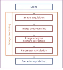
5.1. General workflow in image processing
In general, image processing methods are used for the automatic analysis of scenes acquired by camera systems. The employed image analysis methods in this article are new with respect to the process specific challenges (for further details [8], [6], [4]).
The general workflow this article follows is depicted in Figure 3.
MBT and SRF
5.2. Pre-processing
After the acquisition of image data of the scene of interest by an infrared camera system, the pre-processing prepares the raw image data for the main analysis. For the pre-processing, this article introduces three methods that were developed to support a successful detection of alternative fuel ([6], [3])
5.2.1. Evaluating the visibility of the fuel due to dust exposure
Due to dust exposure, an evaluation of the visibility of the fuel is needed, because a high dust exposure may cause a significant occlusion of fuel. Thus, homogeneous gray values in this specific part of the image are produced (Figure 4).
Image processing
Image acquisition Scene
Image preprocessing
Image analysis/
Feature extraction Parameter calculation
Scene interpretation
Figure 3: General workflow for scene analysis The basis is a camera system that ensures
the visibility of the objects of interest. In this application, an IR-camera (10,6 µm).
In a next step, it is necessary to improve the obtained raw images with prepro- cessing methods or to emphasize image content of interest, in order to facilitate the following analysis. The analysis often incorporates the segmentation of speci- fic image regions, the extraction of gray value characteristics, or texture features.
Thus, parameters are derived that allow a scene interpretation and consequently enable human intervention or automatic process control.
The introduction of a view condition parameter allows to estimate the visibility of the fuel. The parameter represents the image contrast and is calculated by the sum of the absolute values of the gradi- ents in a region where fuel can occur. For further automatic image analysis fitting images are pre-selected by a comparison of the parameter with a threshold.
Figure 4: IR-camera images of multi-fuel burner at heavy dust exposure (poor view conditions)
MBT and SRF
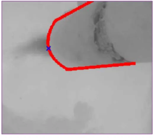
5.2.2. Determining whether the burner tip is still in the right position or whether cakings cover fractions of the fuel To verify the correct burner position, an automatic check, if the burner tip is still in the right position or whether cakings cover fractions of the fuel, is essential. Thus, constant acquisition conditions can be guaranteed. Due to burner maintenance or after a demounting of the camera, changed burner position may occur. Hence, only a correct burner position enables an accurate estimation of predetermined regions for further evaluation and comparability. The approach used in this article is template matching of the burner tip. The templates
are represented by simple contour lines of the burner tip (Figure 5, red outline) generated from varying rotation angles.
The position of the burner tip itself is re- presented by the exit point of the fuel at the front of the burner (Figure 5, blue cross).
With constant acquisition conditions ensured, the position can be determined within a quadratic acceptance window of a few pixels. This localization of the burner tip makes sure that the recording
constellation is not changed significantly. Figure 5: Template matching for burner tip detection
Figure 6: Cropping image to region of interest (red rectangle) for fuel detection
5.2.3. Identify cakings in cropped image to prevent false detections The next pre-processing method uses the output of the previous two and first crops a region of interest from the image where the fuel detection later takes place in the main analysis (Figure 6).
MBT and SRF
However, this region may contain cakings on the kiln wall caused by the rotation of the kiln, which block the view on the fuel.
To prevent false detection because of the similar temperatures of cakings and fuel, a segmentation of cakings is necessary. The segmentation is based on the evaluation of the gray values at the image edge. If cakings appear, also gray value break-ins appear which are detected by minima detections. These minima are used as seed points for a subsequent region growing method which is the result of the segmen- tation. Figure 7 shows an example of the segmentation method.
5.3. Image analysis
The described pre-processing methods ensure an undisturbed detection of the alternative fuel. The main analysis of the fuel is split into two methods depending on the appearance of the fuel. Due to the concentrated input, the fuel appears very concentrated close to the burner tip. With increasing distance to the burner tip the fuel scatters and individual as well as ag- glomerated fuel particles can be observed.
The first aspect is obtained by a low-pass filter and a column-by-column minima detection. The second one, including de- tection of particles and agglomerations, is done by SIFT detection. The combination
Figure 7: Result after segmentation process of cakings and fuel
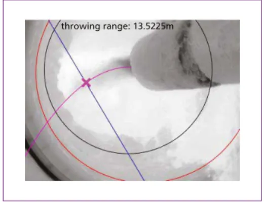
of both methods leads to an estimation of the alternative fuel streak line ([6] and Figure 8).
5.4. Parameter calculation
On the basis of the detected streak line, parameters are derived, which are integrated in the online monitoring of the process optimization software. For example, the throw distance of the alternative fuel (Figure 8, magenta line) can be calculated to estimate the combustion behavior and to adapt the burner settings. The angle the fuel is leaving the burner tip is another important parameter. With controlling the angle by adjusting the burner settings it can be guaranteed that the fuel is completely converted and do not negatively affect the product quality. The derived parameters guarantee the adjustment of the control and thus the optimization of the combustion behavior of the alternative fuel.
throwing range: 13.5225m
Figure 8: Estimation of the fuel streak line (purple) and calculation of throw distance
MBT and SRF
6. The inspect pro control C system
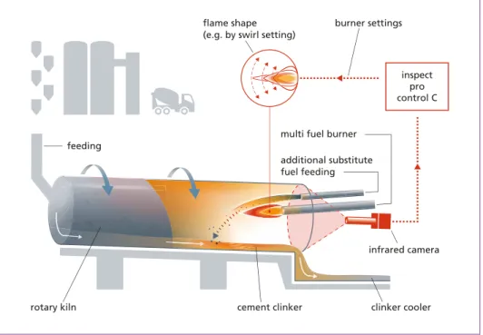
The developed and above described methods of (a) pre-processing IR-image data, (b) analyzing the latter and (c) calculating characteristic parameters of the combustion behavior are bundled and integrated as modules in the software system inspect pro control C (schematic link in Figure 9). Based on the IR-images pre-/processed in this system, parameters are derived and the process control of the burner settings is adapted to optimize operations. The conventional and fuzzy control implemented in the inspect core modules ensure a significant optimization relying on the characteristics recorded.
The derived parameters are transmitted through the inspect system directly to the burner and process-control systems of the incinerators (Figure 9). Examples for input variables of the control systems are herein the size of the fire source and its intensity.
Simultaneously, all of these parameters are visualized via prefabricated interfaces. The inspect system thereby archives all process data in a database and visualize them via Ethernet-coupled graphical user interfaces (e.g. in the control room).
Due to the modular design, the system successfully calculates the combustion cha- racteristics even when there is a wide variety of fuel fractions such as in the cement industry. The system contains e.g. software modules for the connection to multiple camera systems, the analysis of images, a fuzzy control environment, interfaces to process control systems and modules to store images and values in database.
flame shape (e.g. by swirl setting)
burner settings
feeding
cement clinker rotary kiln
infrared camera multi fuel burner
additional substitute fuel feeding
clinker cooler inspect pro control C
Figure 9: inspect pro control C – control system of a rotary kiln, schematic illustration
Source: ci-Tec GmbH: inspect pro control C. 2016
MBT and SRF
In summary, characteristic parameters of the burning process are required to achieve, via intervention of the control system, a stable combustion and defined temperature distributions. Hence, a consistently high product quality is reached which is essential for the substitution of oil and coal dust through alternative fuels. Regarding the political framework of sustainability, reducing CO2, and energy consumption, maintaining a high product quality and increasing the service life of the equipment becomes more and more determined. The development of a control system as presented in this article can significantly contribute to reach these goals. These aspects drive the objective of the Comfeb project and symbolize one motivation to build, develop and refine a secure and reliable process-control software which addresses the referred challenges. Due to the close cooperation in the Comfeb project between ci-tec, the Karlsruhe Institute of Technology, and the cement industry, the development of the inspect system for the cement industry is ensured. The validation of the system as an industrial-ready solution is currently executed at different plants in Germany.
7. Preliminary results of the Comfeb project – an industrial application project – and conclusion
Combustion behaviors of standard fuels with low-rank fuels or pure low-rank fuel combinations are complex and difficult to control. Camera-based measurement and analysis provide non-standard parameters. With their use, the combustion behavior is characterized. Further, the objective of the parameter derivation based on IR-Data is to develop a control system that optimizes the thermal burning process of different fuel fractions.
Currently, the issue of increased alternative fuels and accompanying different burning behavior has not yet been solved, at least to a satisfying state. Moreover, a large part of fuel still consists of fossil fuel to ensure an adequate product quality. Prospectively, the cement producer’s ambition is to use more and more alternative fuels to the point where they replace fossil fuels completely. One main problem is that the characteristics of alternative fuels are varying significantly. Thus, the combustion process is partly imperfect which leads to a lower quality of the product. Heat, dust, and permanent rotation further hinder to install measurement equipment inside a rotary kiln.
Remedying this limitation, an infrared camera, which can track fuel particles, will improve the burner operation in several ways. The retrieved data represents the basis of any optimization process with appropriate methods.
In addition to pre-selecting images by analyzing the view conditions, the system also ensures that changes of the camera or burner position do not negatively affect the following image analysis. Hence, the correctness of pre-defined image regions can be guaranteed, which are employed for evaluating and the comparing of the parameters.
Moreover, possible false detections caused by cakings are avoided by an appropriate detection method. The estimation and calculation of the fuel streak line not only con- siders the compact part but also the particles of the fuel. The derived parameters of
MBT and SRF
the system can ultimately be used to support the plant operator or to enable an online and automatic burner control.
Finally, inspect pro control C can be used to retrofit all rotary kiln plants. It allows for reducing energy consumption while still maintaining a high product quality and increasing the service life of the equipment. By adjusting the calculated characteristics using classical methods or fuzzy controls, thermal combustion processes and burning behavior are optimized. Consequently, this optimization results in an increased energy output, decreased emissions of e.g. CO2, and a stable combustion process. In addition to these benefits, lower operating costs and a reduced use of fossil fuels are further advantages for plant operators.
Acknowledgements The authors would like to acknowledge the KIC InnoEnergy company for co-funding the research in the Comfeb project.
8. References
[1] Cemcon, U.: M.A.S. Kiln Burner – UNICAL Calciner Burner. 2015 [2] ci-Tec GmbH: inspect pro control C. 2016
[3] Matthes, J.; Waibel, P.; Keller, H.B.: A new infrared camera-based technology for the optimazation of the waelz process for zinc recycling, Minerals Engineering, Bd. 24, Nr. 8, 2011, pp. 944-949 [4] Matthes, J.; Waibel, P.; Keller, H.B.: Detection of empty grate regions in firing processes using
infrared cameras. In 11th International Conference on Quantitative Infrared Thermography (QIRT), 2012
[5] Vogelbacher, M.; Waibel, P.; Matthes, J.; Keller, H.: Bildbasierte Überwachung alternativer Brenn- stoffe eines Mehrstoffbrenners bei industriellen Verbrennungsprozessen. Forum Bildverarbei- tung, 2016, pp. 297-308,
[6] Vogelbacher, M.; Waibel, P.; Matthes, J.; Keller, S.; Keller, H.B.: Bildbasierte Überwachung und Optimierung der Verbrennung von alternativen Brennstoffen bei Mehrstoffbrennern. In: Anla- gebezogenes Monitoring: neue Anforderungen – neue Konzepte. Würzburg: 2016
[7] Vogelbacher, M; Waibel, P.; J. Matthes, J.; Keller, H.B.: Camera-based optimization of alternative fuel combustion with multi-fuel burners. In: 8th European Combustion Meeting, 2017 [8] Waibel, P.: Konzeption von Verfahren zur kamerabasierten Anaylse und Optimierung von Dreh-
rohrprozessen. Karlsruhe Institut of Technology, 2014
[9] Waibel, P.; Vogelbacher, M.; Matthes, J.; Keller, S.; Keller, H. B.: Neuartige Kenngrößen zur Online-Beschreibung des Sonderabfall-Verbrennungsprozesses im Drehrohr einer Industrie- anlage auf Basis von Infrarotaufnahmen. In: Energie aus Abfall, Band 14. Neuruppin: TK Verlag Karl Thomé-Kozmiensky, 2017, pp. 541-552
TK Verlag Karl Thomé-Kozmiensky
Dorfstraße 51
D-16816 Nietwerder-Neuruppin
Tel. +49.3391-45.45-0 • Fax +49.3391-45.45-10 E-Mail: tkverlag@vivis.de
Waste Management
Order now: www. .de
Karl J. Thomé-Kozmiensky
WASTE MANAGEMENT
Luciano Pelloni
Thomé-Kozmiensky und PelloniWASTE MANAGEMENT
Volume 1 Eastern European Countries
1
Rüdiger Margraf
Waste Incineration
Figure 7:
Rough scheme dry hydration CaO Dosing balance
H2O
Dry hydrator CaO
CaO Silo
Ca(OH)2 Ca(OH)2
Silo towards lime dosing TIC
Several plants in Germany have been provided with this technology.
Figure 8 shows a plant, realised with a dry hydrator for a Ca(OH)2 production capacity of approximately 3 t/h.
Figure 8: RDF incineration plant EEW Premnitz / Germany As alternative there is the possibility to install the dry hydrator close to the additive
2 can now be injected
Verbrennungs-rost Gewebefilter Elektro- filter Sprüh-
trockner Kamin
Dampf- kessel MüllkranAufgabe-trichter
Müll- bunkerVerbrennungs-luftgebläseAufgabe-vorrichtungPlatten-wände TrogkettenfördererEntschlackung/
Ammoniak-Wasser- Eindüsung
Kessel- entaschung
Abgaswäscher Druckerhöhungs-gebläse
Adsorbenssilo
Feuerraum Primär- luft
Figure 3:
Karl J. Thomé-Kozmiensky
Volume 2
WASTE MANAGEMENT
Luciano Pelloni
Waste Management Recycling Composting Fermentation Mechanical-Biological Treatment Energy Recovery from Waste Sewage Sludge Treatment Thomé-Kozmiensky und PelloniWASTE MANAGEMENT
2
2
Thomé-Kozmiensky und Pelloni
Karl J. Thomé-Kozmiensky
Volume 3 Recycling and Recovery
WASTE MANAGEMENT
Stephanie Thiel
WASTE MANAGEMENTThomé-Kozmiensky und Thiel
3
, Thiel
5
2
Thomé-Kozmiensky und Pelloni
Volume 6 Waste-to-Energy
WASTE MANAGEMENT
Stephanie Thiel Karl J. Thomé-Kozmiensky
6
WASTE MANAGEMENTK. J. Thomé-Kozmiensky & S. Thiel
WASTE MANAGEMENT Volume 2
KARL J. THOMÉ-KOZMIENSKY STEPHANIE THIEL HRSG.
Copyright © 2011 TK Verlag Karl Thomé-Kozmiensky Alle Rechte vorbehalten.
Das Einspeisen der Daten in Netzwerke ist untersagt.
WASTE MANAGEMENT Volume 3
KARL J. THOMÉ-KOZMIENSKY STEPHANIE THIEL HRSG.
Copyright © 2011 TK Verlag Karl Thomé-Kozmiensky Alle Rechte vorbehalten.
Das Einspeisen der Daten in Netzwerke ist untersagt.
Waste Management, Volume 1 – 6 • CD Waste Management, Volume 2 and 3
289.00 EUR
save 121.00 EUR
Package Price
Editors: Waste Management, Vol. 1 – 2: Karl J. Thomé-Kozmiensky, Luciano Pelloni Waste Management, Vol. 3 – 6: Karl J. Thomé-Kozmiensky, Stephanie Thiel
Waste Management, Volume 5 (2015) ISBN: 978-3-944310-22-0 120.00 EUR Waste Management, Volume 1 (2010) ISBN: 978-3-935317-48-1 includes translations in Polish, German 20.00 EUR Waste Management, Volume 2 (2011) ISBN: 978-3-935317-69-6 CD includes translations in 50.00 EUR + CD Waste Management, Volume 2 ISBN: 978-3-935317-70-2 Polish and German
Waste Management, Volume 3 (2012) ISBN: 978-3-935317-83-2 CD includes translations in 50.00 EUR + CD Waste Management, Volume 3 ISBN: 978-3-935317-84-9 various languages
Waste Management, Volume 4 (2014) ISBN: 978-3-944310-15-2 50.00 EUR
Waste Management, Volume 6 (2016) ISBN: 978-3-944310-29-9 120.00 EUR
IRRC IRRC
Bibliografische Information der Deutschen Nationalbibliothek Die Deutsche Nationalbibliothek verzeichnet diese Publikation in der Deutschen Nationalbibliografie; detaillierte bibliografische Daten sind im Internet über http://dnb.dnb.de abrufbar
Thomé-Kozmiensky, K. J.; Thiel, S.; Thomé-Kozmiensky, E.;
Winter, F.; Juchelková, D. (Eds.): Waste Management, Volume 7 – Waste-to-Energy – ISBN 978-3-944310-37-4 TK Verlag Karl Thomé-Kozmiensky
Copyright: Elisabeth Thomé-Kozmiensky, M.Sc., Dr.-Ing. Stephanie Thiel All rights reserved
Publisher: TK Verlag Karl Thomé-Kozmiensky • Neuruppin 2017
Editorial office: Dr.-Ing. Stephanie Thiel, Elisabeth Thomé-Kozmiensky, M. Sc.
Janin Burbott-Seidel and Claudia Naumann-Deppe
Layout: Sandra Peters, Anne Kuhlo, Ginette Teske, Claudia Naumann-Deppe, Janin Burbott-Seidel, Gabi Spiegel and Cordula Müller
Printing: Universal Medien GmbH, Munich
This work is protected by copyright. The rights founded by this, particularly those of translation, reprinting, lecturing, extraction of illustrations and tables, broadcasting, micro- filming or reproduction by other means and storing in a retrieval system, remain reserved, even for exploitation only of excerpts. Reproduction of this work or of part of this work, also in individual cases, is only permissible within the limits of the legal provisions of the copyright law of the Federal Republic of Germany from 9 September 1965 in the currently valid revision. There is a fundamental duty to pay for this. Infringements are subject to the penal provisions of the copyright law.
The repeating of commonly used names, trade names, goods descriptions etc. in this work does not permit, even without specific mention, the assumption that such names are to be considered free under the terms of the law concerning goods descriptions and trade mark protection and can thus be used by anyone.
Should reference be made in this work, directly or indirectly, to laws, regulations or guide- lines, e.g. DIN, VDI, VDE, VGB, or these are quoted from, then the publisher cannot ac- cept any guarantee for correctness, completeness or currency. It is recommended to refer to the complete regulations or guidelines in their currently valid versions if required for ones own work.