sFLASH - PRESENT STATUS AND COMMISSIONING RESULTS
∗S. Ackermann, A. Azima, J. B¨odewadt, F. Curbis, M. Drescher, E. Hass, M. Mittenzwey, T. Maltezopoulos, V. Miltchev†, J. R¨onsch-Schulenburg, J. Rossbach, R. Tarkeshian, Hamburg University, Hamburg, Germany
H. Delsim-Hashemi, K. Honkavaara, T. Laarmann, H. Schlarb, S. Schreiber, M. Tischer, DESY, Hamburg, Germany
S. Khan, DELTA, Dortmund, Germany R. Ischebeck, PSI, Villigen, Switzerland
Abstract
The sFLASH-experiment has been built at the Free- Electron Laser in Hamburg (FLASH) to study the high- gain-FEL amplification of a laser seed from a high har- monic generation (HHG) source. Ideally, the HHG seed can be amplified up to a GW-power level, improving both the shot-to-shot stability and the longitudinal coherence of the FEL-pulse.
In 2010/2011 the sFLASH-components and sub-systems have been fully installed and commissioned within about 300 hours FLASH beam time dedicated to the seeding project. Procedures to achieve a full six-dimensional over- lap between the seed and the electron bunch have been de- veloped and tested. An important milestone reached in the commissioning period is the sFLASH-SASE lasing mode, which was being achieved on a regular basis. A step for- ward towards the next milestone - the direct seeding in the XUV-wavelength range - is the sFLASH-upgrade during the planed FLASH-shutdown in autumn 2011. In this con- tribution the main commissioning results and highlights of the operational experience will be discussed in detail.
INTRODUCTION
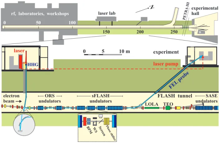
Currently FLASH operates in the SASE mode, deliver- ing photon pulses of wavelength down to 4.1 nm [1]. The XUV-seeding experiment sFLASH gives the possibility to externally seed FLASH with higher harmonics of an optical laser. The project aims at a seeding in the sub-40 nm range, with a stability suitable for user operation. It makes pos- sible to achieve higher shot-to-shot stability at GW-power level with a pulse duration given by the seed pulse in the order of 20 fs FWHM. The longitudinal coherence is ex- pected to be greatly improved. The FEL output is synchro- nized with the external seed laser, thus enabling precise pump-probe experiments. As illustrated in Fig. 1, sFLASH is installed at the end of the linac, upstream of the existing fixed-gap SASE-undulators. With the help of a dedicated optical beamline, the HHG seed can be injected through the collimator section, making use of the electron beam offset of about 20 cm. After amplification in the sFLASH variable-gap undulators, the output radiation can be sep- arated from the electrons by means of a mirror mounted
∗Work supported by BMBF contract No. 05 ES7GU1
†velizar.miltchev@desy.de
in a magnetic chicane downstream. The photons are then reflected either towards the experimental area outside the FLASH tunnel or to the photon diagnostics equipment sit- uated in the tunnel.
UNDULATOR COMMISSIONING
sFLASH is comprised of four variable gap undulators with a total effective length of 10 m. Three 2 m long U32 undulators are followed by a 4 m long U33 undulator.
The latter is a previously decommissioned device which is reused for sFLASH after refurbishment [2]. Undulator parameters are listed in Table 1. Further details on the
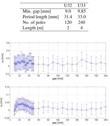
Table 1: Parameters of sFLASH Undulators
U32 U33
Min. gap [mm] 9.0 9.85 Period length [mm] 31.4 33.0
No. of poles 120 240
Length [m] 2 4
Figure 2: Electron beam position as a function of the gap of thefirst sFLASH-undulator at a BPM downstream.
undulator commissioning are described elsewhere [2]. In order to minimize the undulators impact on the electron or- bit and to compensate the residualfield integrals a set of air coils is located upstream of all undulators. Besides the
c○2011byIPAC’11/EPS-AG—ccCreativeCommonsAttribution3.0(CCBY3.0)
laser HHG
LOLA TEO ORS
undulators electron
beam
SASE undulators sFLASH
undulators
FLASH tunnel experiment laser lab
rf, laboratories, workshops
experimental hall
PETRA
N III
0 50 100
150 200 250 *
0 5 10 m
laser pump
FEL probe
Phase shifter Scr
een BPM WS
Figure 1: The FLASH facility (top) is comprised of a 260 m long tunnel housing the linac and the SASE-undulators, followed by an experimental hall. sFLASH is located in the section upstream of the SASE-undulators. Seed pulses from the HHG source in the building adjacent to the FLASH tunnel are injected into the electron beam pipe downstream of the last dipole of the energy collimator (left). By means of an IR-beamline (dashed red line), a fraction of the optical drive laser energy can be used for pump-probe experiments. The dashed bordered boxes show detailed views of the XUV-injection and the undulator intersections.
magnetic measurements and magnetic tuning performed at a measurement bench, the undulator commissioning in- cluded beam-based calculation of the feed-forward (FF) tables for the settings of the undulator air-coils. Experi- ence with other undulators shows, that magnetic measure- ments are not sufficient for a precise FF-tables calculation.
Therefore electron beam-based FF-tables are mandatory.
The FF-tables are dependent on electron optics thus optics, which is close to the design sFLASH electron optics is re- quired. The available downstream-BPMs have been used to draw up orbit response matrices and FF-tables for each of the air coils. As a result of this procedure the sFLASH undulators show a tolerable impact on the electron orbit for any gap. A measurement of the electron beam position as a function of the gap of thefirst sFLASH-undulator is shown in Fig. 2.
INJECTION BEAMLINE AND TRANSVERSE OVERLAP
The XUV-seed radiation is guided through a 15 m long differentially pumped transfer line from a laser laboratory into the adjacent accelerator tunnel and into the electron
beam pipe. This transfer line includes two motorized mir- ror chambers to steer the laser beam and thus to control the spatial overlap between the electron and the photon beam.
The maximal theoretical overall transmission of the beam-
Figure 3: The schematic of the sFLASH beamline. It illus- trates the injection beamline for the seed laser and the beam diagnostic stations. Exemplary XUV beam profiles along the undulator using a mirror with a focal length of 6.25 m are also shown [3].
line is estimated to be about 20 %. However since there is no possibility to measure the HHG seed pulse energy after injection, this theoretical value could not be verified experimentally during the commissioning period. In more c○2011byIPAC’11/EPS-AG—ccCreativeCommonsAttribution3.0(CCBY3.0)
details the injection beamline has been described in [3]. In its present design the injection beamline has one focusing mirror for control of the HHG seed transverse size in the undulator. Three mirrors of different focal lengthsfcan be remotely exchanged (f: 6.25 m; 7 m; 8.5 m) [3]. This gives the possibility to focus the XUV beam at different posi- tions along the undulator. For an effective seeding process the seed beam power should exceed the shot noise power of the electron beam. Ideally, the XUV beam should be fo- cused in the beginning of thefirst undulator module match- ing the beam size of the electron beam. On the other hand the Rayleigh length of the XUV beam should not be smaller than the FEL gain length. For this reason, the XUV-beam sizes were measured along the undulator to get an esti- mate for the waist spot size and position. Figure 3 shows an example of XUV beam profiles measured at three dif- ferent positions along the undulator for a focal length of 6.25 m. It has been observed, that the HHG-beam has an elliptic shape with the semi-axis being tilted. The beam shape can be explained by the beam shape of the HHG drive laser, which also shows an elliptical shape. One could think of two reasons for the tilt: the beamline geometry, which tilts the coordinate system from the HHG source to the undulator and an astigmatism, which leads to different focus positions in the vertical and horizontal plane. In the case off=6.25 m the foci of the XUV beam are within the first undulator module. The beam parameters were esti- mated byfitting the data using a Gaussian beam propaga- tion model. The beam waist sizes within the undulator are wx0= 0.693 mm in the horizontal andwy0= 0.427 mm in the vertical plane.
One of the key challenges for seeding is to achieve the
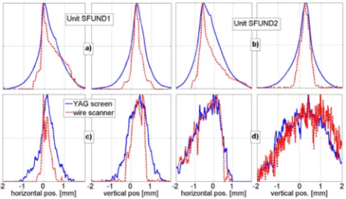
Figure 4: Electron beam profiles (upper row a) and b)) and XUV-laser beam profiles (lower row c) and d)) each mea- sured with cerium-doped YAG screens and EMCCD cam- eras (blue lines) and with wire scanners (red lines) after ad- justing the transverse laser position. The profile intensity is normalized to the same peak value for each measurement.
transverse overlap between the XUV-seed and the electron bunch with an adequate coupling efficiency. In order to obtain the overlap, diagnostic units are installed at either end of the undulator modules. These compact diagnos- tic units include BPMs, OTR-screens and wire scanners
to measure the electron beam size and position as well as YAG-screens for transverse diagnostics of the HHG seed.
The achieved accuracy of the overlap between the seed and electron bunch is about 50μm, 50μradin both transverse planes. The example in Fig. 4 shows the electron- and the XUV beam profiles measured with the screens and the wire scanners after adjusting the transverse overlap. Both beams were aligned within 50μmand 50μradin angle and posi- tion. Further details on the experimental set up and mea- surement results are given in [4].
ELECTRON BEAM AND XUV-SEED TEMPORAL OVERLAP
As discussed in [5], two techniques are used to achieve the longitudinal overlap at sFLASH. Thefirst is based on a streak camera measurement of the arrival time of the laser pulse and the electron bunch using spontaneous undulator radiation with a resolution in the picoseconds range (coarse overlap). The second is a modulator-radiator-based sys- tem [6] with a sub-100 fs resolution (fine overlap). For the coarse overlap a silver coated screen placed after a short electromagnetic undulator (the modulator, 1 m length, 5 periods, 20.0 cm period length), reflects a fraction of the 800 nm HHG-drive laser radiation and spontaneous radi- ation from the undulator to a fast photomultiplier and to a streak camera at the same time. Both light pulses tra- verse a joint beam line to reach the detectors. The nominal streak camera resolution is about 200 fs. For a more accu- rate overlap of the seed pulse with the electron bunch, the coherent radiation from a second electromagnetic undula- tor (the radiator) is used. The temporal overlap between the IR-light and the electron bunch enhances the radiation intensity. In the modulator the 800 nm laser beam is inter- acting with the electron bunch. In this process the electrons are energy modulated. This effect will induce a charge den- sity modulation after the beam passes through the chicane with anR56that can be varied up to 140μm. The density- modulated beam then passes through the second undulator, the radiator, which is tuned to the fundamental or to the second harmonic of the modulator. It emits coherent radi- ation, the intensity of which depends quadratically on the amplitude of the charge density modulation. This radiation is measured with a CCD camera and a UV-VIS spectrome- ter. The resolution achieved with this method is about 50 fs.
UNDULATOR GAP ADJUSTMENT - FREQUENCY OVERLAP
Two options for undulator gap adjustment have been considered and tested experimentally:
1. Tune each undulator individually by comparing the spontaneous radiation spectrum with the HHG- reference spectrum.
2. Close all undulator gaps simultaneously using the un- dulators magnetic calibration.
c○2011byIPAC’11/EPS-AG—ccCreativeCommonsAttribution3.0(CCBY3.0)
Figure 5: (a) Single-shot spectra of the SASE-radiation. (b) Single-shot spectra of the HHG seed. The red curve is the average over all single shots.
Concerning option 1 one has to note, that the effective size of the sFLASH photon out-coupling mirror is in the order of 3 mm. The distance between the mirror to the far most undulator is ∼104mm. Due to the weak intensity of the undulator radiation, pinhole apertures have not been used to reduce the angular acceptance of the beamline. Because of the θ∼1mrad acceptance angle, one could expect a significant spectral broadening due toΔλ/λ∝γ2θ2. For the same reason, the second harmonic could also signif- icantly contribute to the measured spectra and thus the measurement accuracy is further reduced. The initial idea was to use the short-wavelength “edge” created by the on- axis radiation for tuning the undulator gap. This challeng- ing task becomes even harder to accomplish with a com- pressed electron beam (off-crest) of energy spreadσγ/γup to≈10−2. Moreover, if there is dispersion in the electron beamline, then the undulator line becomes broader due to increased beam divergence. The experimental results show, that gap values determined this way are reproducible on a level of ∼50μm corresponding to Δλ/λ∼1%. This value is comparable to the FEL-bandwidth. Therefore one can conclude, that adjusting each gap separately by look- ing at the spontaneous radiation spectrum is not sufficiently accurate. This method might result in a substantial degra- dation or even loss of the FEL-gain due to wavelength mis- match between the undulators.
In contrast, option 2 is much faster to perform and has the advantage to simultaneously determine the gaps all undu- lators in a consistent way using the undulator calibration curves. Since the electron beam energy is known with an accuracy of about 1 % this procedure has to be repeated a few times till the full frequency overlap is achieved. In Fig. 5 single-shot SASE-FEL- and HHG seed spectra are compared. As apparent from these plots the wavelength offset between the two spectral peaks is in the order of the spectrometer resolutionΔλ/λ≈0.001.
SASE-OPERATION
The sFLASH-SASE lasing mode is an important mile- stone reached during the commissioning period. This op-
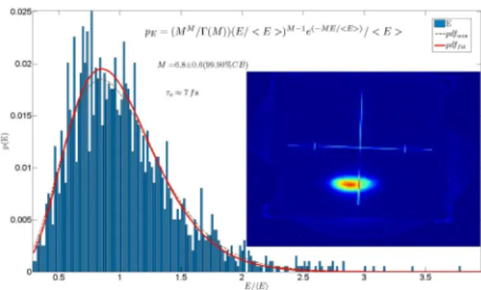
Figure 6: Probability distribution of the energy in the SASE-pulses and transverse profile of the SASE radiation on the YAG screen(inset).
eration mode, which has been achieved on a regular ba- sis, demonstrates that the FEL-amplifier is adjusted to the right resonant frequency and with sufficiently high FEL gain. Typically sFLASH-SASE has been tuned in the linear regime with a gain in the order of105−106. In addition, the shot-to-shot energyfluctuations of the SASE-FEL ra- diation can be used to estimate the XUV-pulse duration by fitting the measured probability distribution to the gamma- distribution [7]. In the example shown in Fig. 6 this anal- ysis yields a photon pulse duration of about 50 fs. In this particular case the coherence timeτchas been estimated to be about 7 fs, which corresponds to a power gain length of about 0.85 m.
HHG SOURCE
The sFLASH HHG seeding source is driven by a CPA laser system running at 10 Hz, which matches the repeti- tion rate of the linac. Pulses from a Ti:Sapphire oscilla- tor, that is synchronized to the 1.3 GHz master oscillator clock of the accelerator RF, are amplified in a combined re- generative and multipass-amplifier. It produces short (35 fs FWHM) pulses with an energy of up to 20 mJ. These pulses are transported to the HHG vacuum chamber located in a pit beneath the optical table, where the high harmonic gen- eration takes place in a nobel gas (Ar)filled capillary. As it has been studied in [8], an efficient harmonic generation is only achieved in a narrow range around the optimal val- ues of the main source parameters like driving laser inten- sity, target position, target pressure and target length. The XUV energy in 21st harmonic of the 800 nm drive laser after optimization is about 2 nJ. This is the estimated full HHG-pulse energy at the position of the source and not the energy, which can be coupled to the electron beam. The effective pulse energy available for seeding is reduced by the overall injection beamline transmission. The energy coupled to the electron beam is further reduced by another
∼90 % due the relatively large HHG-beam transverse size in the undulator i.e. due to the poor coupling with the elec- tron beam. With an XUV-pulse length of about 20 fs the c○2011byIPAC’11/EPS-AG—ccCreativeCommonsAttribution3.0(CCBY3.0)
available seed power can be estimated to be in the order of 1000 W, which is marginal for an effective seeding.
OUTLOOK
In order to increase the effective seed power and the flexibility of the HHG-injection beamline various improve- ments in the present sFLASH set up are going to be made during the planed FLASH-shutdown in autumn 2011.
This upgrade includes modification of the HHG-drive laser compression scheme, additional on-line HHG-diagnostics as well as installation of adaptive optics in the HHG- injection beamline. The plans of the project extend beyond the demonstration of direct HHG seeding. Seeding with frequency-chirped HHG-pulses and studies on the impact of the chirp on the FEL-radiation properties is an essential part of the sFLASH future research program. By means of a spectral phase-modulator one can investigate the possibil- ities to control the coherent properties and the length of the FEL-pulses. Furthermore, the higher harmonics of the lon- gitudinal charge density modulation, which occur during the FEL-process, can be used to study an HGHG-seeding option in the main FLASH-undulators.
ACKNOWLEDGMENTS
Without the help from many groups at DESY (among them FLA, HASYLAB, MCS, MEA, MIN, MKK, MPY, MVS, ZBAU and ZM) the preparation of all sFLASH com- ponents would not be conceivable. Their support is grate- fully acknowledged. The project is supported by BMBF under contract No. 05 ES7GU1.
REFERENCES
[1] S. Schreiber et. al.,Status of the FEL User Facility FLASH, Proceedings of FEL’11, Shanghai, TUPB04.
[2] M. Tischer et al., WEPD014, proceedings IPAC 2010, 3114- 3116.
[3] J. B¨odewadt et. al.,Commissioning Results of the Photon- Electron Diagnostic Unit at sFLASH, Proceedings of DI- PAC’11, Hamburg.
[4] E. Hass et. al.,Transverse Overlap Diagnostics with Wire Scanners in the XUV-seeding Experiment at FLASH, Pro- ceedings of FEL’11, Shanghai, TUPB01.
[5] R. Tarkeshian et al., Femtosecond resolved determination of electron beam and xuv seed pulse temporal overlap in SFLASH, Proceedings of PAC’11, New York, WEOCN6.
[6] S. Khan et al., Proceedings of PAC07, TUPMN023, 965- 967.
[7] E. L. Saldin, et. al., Opt. Comun. 148, 383-403 (1998).
[8] M. Mittenzwey, High Harmonic Generation for the XUV seeding experiment at FLASH, PhD Thesis, University of Hamburg.
c○2011byIPAC’11/EPS-AG—ccCreativeCommonsAttribution3.0(CCBY3.0)