Department 04: Computer Science
Leveraging Model-Based Techniques for Runtime Adaptivity in Software
Systems
A thesis in fulfillment of the
thesis requirement for the degree of Master of Science
in
Informatik (Computer Science)
Submitted by
Mahdi Derakhshanmanesh
Supervisor: Prof. Dr. J¨urgen Ebert, Institute for Software Technology, Department 04
1. Reviewer: Prof. Dr. J¨urgen Ebert, Institute for Software Technology (IST), Univer- sity of Koblenz-Landau (Germany)
2. Reviewer: Dr. Ladan Tahvildari, Software Technologies Applied Research (STAR), University of Waterloo (Canada)
Koblenz, Rheinland-Pfalz, Germany, December 2010
I hereby declare that I am the sole author of this thesis. This is a true copy of the thesis, including any required final revisions, as accepted by my examiners.
I understand that my thesis may be made electronically available to the public.
Erkl¨arung
Ich versichere, dass ich die vorliegende Arbeit selbst¨andig verfasst und keine anderen als die angegebenen Quellen und Hilfsmittel benutzt habe.
Abstract
The present Master’s thesis seeks to develop a better understanding of ways to achieve runtime adaptivity in software by using explicit models. Such a runtime model partially reflects data about the inner state of the software to be adapted, and it provides sub-models that describe behavior. Behavior is modeled using the language of UML Activity Diagrams, where an action is mapped to an existing method implementation that is available in the software to be adapted. This software is the managed software, or adaptable software.
It is causally connected to the runtime model to exchange its state data. In addition, the behavior that is described in the runtime model, is interpreted at predefined points of the software’s control flow. A model interpreter component executes an associated Activity model and replaces the existing control flow of the managed software. Adaptivity is achieved by transforming the model at runtime. Transformations include changes to the captured state data, or to the behavior descriptions.
In this thesis, we focus on a scenario, where existing software shall be migrated towards a Self-Adaptive Software System (SASS). In cooperation with the Software Technologies Applied Research (STAR) laboratory at the University of Waterloo in Canada, we designed a framework that is based on a model-centric architecture to achieve adaptivity. Early results of this collaboration are published in [2].
TheGraph-based Runtime Adaptation Framework (GRAF) is an implementation of the proposed framework, which utilizes TGraphs and its accompanying technologies as the enabling technology for modeling and manipulating a runtime model. To apply GRAF, and in order to test our approach in practice, we perform a case study with OpenJSIP, an open-source SIP server for VoIP telephony. Although our runtime models are simple at the moment, we are able to show the feasibility of our model-centric approach to runtime adaptivity.
Acknowledgements
I would like to express my appreciation to my supervisor, Prof. Dr. J¨urgen Ebert from the University of Koblenz-Landau (Germany), for giving me the opportunity to do research and work on my Master’s thesis abroad, by establishing the connection to the Software Technologies Applied Research (STAR) laboratory. J¨urgen, thank you once more for your time and patience, as well as for supporting me with your experience, throughout my research.
My gratitude also goes to Prof. Dr. Ladan Tahvildari. Thank you so much for inviting me to STAR at the University of Waterloo (Canada), and for giving me the opportunity and excellent facilities to work at the University of Waterloo. Dear Ladan, I highly appreciate your dedication, which made this collaboration possible. I especially like to thank you for your invaluable feedback on how to present research details appropriately.
I enjoyed every work day with you at the lab, Mehdi. Thank you a lot for all the many hours of fruitful discussions. I am glad we were able to work together so closely; that was a real privilege. More than that, I’d like to thank you for being an awesome friend. The many funny moments we shared, even after work, were just great.
Greg, I’d like to thank you for your excellent work on putting GRAF into practice in the case studies. You did a fantastic job and provided me with valuable insights on ways to improve the framework and how to make it more usable.
The most special thanks go to my parents and to my dear brothers. You always supported me with love and attention.
Table of Contents
List of Tables viii
List of Figures x
List of Listings xii
List of Algorithms xiii
1 Introduction 1
1.1 Self-Adaptive Software Systems . . . 1
1.1.1 Definition . . . 1
1.1.2 Abstract Reference Architecture . . . 2
1.1.3 Self-* Properties . . . 2
1.2 Challenges and Goals . . . 4
1.2.1 Vision . . . 4
1.2.2 Design Rationales . . . 6
2 Related Work 8 2.1 Background . . . 8
2.1.1 Graph Technology . . . 8
2.1.2 Source Code Annotations . . . 12
2.1.3 Aspect-Oriented Programming . . . 13
2.1.4 The Session Initiation Protocol . . . 14
2.2 Related Approaches . . . 16
3 Solution 18
3.1 System Architecture . . . 18
3.1.1 Adaptable Software . . . 18
3.1.2 Graph-based Runtime Adaptation Framework . . . 21
3.2 Runtime Behavior . . . 24
3.2.1 Sensing Scenario . . . 25
3.2.2 Controlling Scenario . . . 26
3.2.3 Effecting Scenario . . . 27
3.2.4 Interpreting Scenario . . . 28
3.2.5 External Controlling Scenario . . . 29
4 Implementation 30 4.1 Project Overview . . . 30
4.2 Instrumentation of Legacy Software . . . 32
4.2.1 Annotation Types . . . 32
4.2.2 Runtime Model Generation . . . 35
4.2.3 Binding Adaptable Software to GRAF . . . 36
4.3 Runtime Modeling . . . 40
4.3.1 Schema . . . 41
4.3.2 Model Management . . . 43
4.3.3 Model Interpretation . . . 45
4.4 Runtime Adaptation . . . 48
4.4.1 Adaptation Rules . . . 48
4.4.2 Rule Engine . . . 50
5 Case Study 52 5.1 Scenario . . . 52
5.1.1 Adaptivity Goals . . . 52
5.1.2 Simulation Setup . . . 53
5.2 Experimentation . . . 54
5.2.1 Exposing State Information . . . 54
5.2.2 Parameter Adaptation . . . 56
5.2.3 Compositional Adaptation . . . 58
5.3 Results and Discussion . . . 59
6 Conclusions and Future Directions 62 6.1 Summary and Contributions . . . 62
6.2 Future Work . . . 64
Appendices 67
A Runtime Model Schema 68
B Runtime Model Snapshots 76
C Adaptation Rules 79
References 90
List of Tables
3.1 Interfaces that need to be provided by any adaptable software. . . 20 5.1 Results of our case study with OpenJSIP and GRAF at different call rates. 60
List of Figures
1.1 Abstract architecture of a self-adaptive software system (SASS). . . 2
1.2 Hierarchy of self-* properties, according to [38]. . . 3
2.1 Sample TGraph schema as a UML class diagram. . . 9
2.2 Sample TGraph as a UML object diagram. . . 10
3.1 A SASS that is using GRAF to achieve adaptivity. . . 19
3.2 Steps involved in the sensing scenario of GRAF. . . 25
3.3 Steps involved in the controlling scenario of GRAF. . . 26
3.4 Steps involved in the effecting scenario of GRAF (for each adaptation rule). 27 3.5 Steps involved in the interpreting scenario of GRAF. . . 28
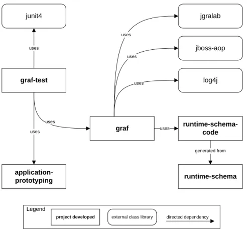
4.1 GRAF with related projects and their dependencies. . . 31
4.2 Instrumentation steps for Adaptable Software to run with GRAF. . . 32
4.3 GRAF’s Middleware Adapters (UML Class Diagram). . . 38
4.4 The root vertex of the runtime model schema. . . 41
4.5 Overview of sub-schema for state variables. . . 42
4.6 Extract of behavioral model schema with commonly used types. . . 42
4.7 An overview of the essential interfaces and abstract classes involved in model management. . . 44
4.8 Interfaces and (abstract) classes for model interpretation. . . 45
4.9 The main interfaces and (abstract) classes for controlling runtime adaptation. 49 5.1 The runtime model for parameter adaptation (UML Object Diagram). . . . 57
5.2 The generated default Activity in the runtime model TGraph for composi-
tional adaptation (UML Activity Diagram). . . 59
A.1 The modeling project for the runtime model schema is organized into these packages. . . 68
A.2 The runtime model consists of state variables and activities. . . 68
A.3 The state variables used for storing sensed data. . . 69
A.4 The activity with related elements. . . 70
A.5 A detailed view on the partition element. . . 71
A.6 The essential elements for modeling control flow. . . 72
A.7 Nodes can be connected to each other via a flow. . . 73
A.8 Data is represented as input and output. . . 74
A.9 An overview on the activity and its relation to nodes and partitions. . . 75
B.1 The default runtime model for the compositional adaptation (abstract syntax). 77 B.2 The blocking runtime model for the compositional adaptation (abstract syn- tax). . . 78
List of Listings
2.1 Sample GReQL query. . . 10
2.2 Sample GReQL constraint using the exists quantifier. . . 11
2.3 A GReQL query embedded in Java. . . 12
2.4 Sample definition of Java annotation type. . . 13
2.5 Use of Java annotation type. . . 13
4.1 Use of the @StateVar annotation. . . 33
4.2 Use of the @StateVar annotation. . . 33
4.3 Use of the @InterpretationPoint annotation. . . 34
4.4 Use of the @AtomicAction annotation. . . 34
4.5 Use of the @AtomicAction annotation for default behavior. . . 34
4.6 Pointcut expression for propagating integer values to the runtime model on write access (set) of @StateVar and @SyncStateVar fields. . . 36
4.7 Advice code for the propagation of values to the RuntimeModelGraph. . . . 37
4.8 Implemented template method in IntegerStateVariableAdapter. . . 39
4.9 Advice code for calling the ModelInterpreterImpl. . . 39
4.10 The IModelInterpreter interface details. . . 46
4.11 Template for writing an adaptation rule. . . 50
5.1 Approximation of system load in Proxy counting CSTs. . . 55
5.2 Preparation of Proxy for parameter adaptation to block new registrations. . 56
5.3 GReQL expression that represents the condition in StartBlockingParamRule. 56 5.4 Transformation that enables blocking in StartBlockingParamRule. . . 57 5.5 Preparation of Proxy for compositional adaptation to block new registrations. 58
C.1 AdaptationRule to enable blocking in parameter adaptation of Proxy. . . 79 C.2 AdaptationRule to disable blocking in parameter adaptation of Proxy. . . 80 C.3 AdaptationRule to enable blocking in compositional adaptation of Proxy. . . 82 C.4 AdaptationRule to disable blocking in compositional adaptation of Proxy. . 84
List of Algorithms
1 interpret(activityId, caller, params) . . . 47
Chapter 1 Introduction
1.1 Self-Adaptive Software Systems
Especially since IBM’s autonomic computing initiative [26], software systems that know their environment and context have become a popular field of research. Autonomic com- puting is inspired by the human’s autonomic nervous system which regulates our body’s temperature, depending on the environment’s temperature, without involving explicit de- cision making of the individual. Similarly, next generation software systems shall perform certain tasks on their own, essentially adapting themselves to changes in the operating envi- ronment. Software with this ability can significantly reduce the amount of work for human administrators. In this section, we give an overview on the terminology and definitions used to describe these software systems.
1.1.1 Definition
Autonomic or self-adaptive software is a self-conscious reflective system that is able to modify its own behavior in response to changes in its operating environment [33]. Another definition for self-adaptive software is provided in a DARPA Broad Agency Announcement (BAA) [29]: ”Self-adaptive software evaluates its own behavior and changes behavior when the evaluation indicates that it is not accomplishing what the software is intended to do, or when better functionality or performance is possible.” A self-adaptive software system (SASS) is also called an autonomic/self-managing system [38].
Depending on the publication and focus of research, either one of the terms autonomic or self-adaptive is used to refer to the same category of software systems. It is difficult to draw a clear distinction between these terminologies. Therefore, the terms self-adaptive,
Adaptation Manager (external)
Managed Software
Sensing Effecting
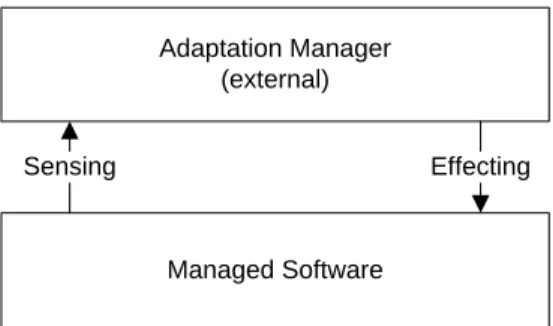
Figure 1.1: Abstract architecture of a self-adaptive software system (SASS).
autonomic computing or even self-managing are very often used like synonyms. Sometimes, autonomic computing is regarded as the more general discipline and from that perspective, self-adaptive software deals with only a part of autonomic computing. In this thesis, the term self-adaptive software is used to generally refer to software that is able to adjust its own behavior at runtime to fulfill its requirements. An SASS is a concrete instance that belongs to the category of self-adaptive software.
1.1.2 Abstract Reference Architecture
As abstractly illustrated in Figure 1.1, a SASS consists at least of the managed software and a controller unit. The controller unit is referred to as adaptation manager (AM) and is able to i) monitor changes in the managed software, ii) analyze the data, iii) plan adaptation steps and finally iv)execute the plan, in order to maintain the desired behavior of the managed software. On the other hand, the managed software is a controlled plant that supports adaptability. This architecture shapes a closed feedback control loop, known as theMAPE-loop [26].
1.1.3 Self-* Properties
Depending on the domain of the managed software and depending on its requirements, the resulting SASS needs to possess certain properties to support adaptability at runtime.
Software adaptability is based on a set of properties that facilitate the observation of oper- ating state transitions and modifying the managed application’s behavior at runtime [39].
These properties are calledself-* properties [4] and can be categorized into different areas of adaptation, as proposed by Kephart and Chess for autonomic computing [26]. Self-*
properties provide some degree of variability related to a specific field of adaptability.
IBM introduced eight of such characteristic properties of an autonomic system [18].
In [38], the Salehie and Tahvildari propose a hierarchical view of these properties, similar
Self-Organizing Self-Adaptiveness
Self-Configuring Self-Healing
Self-Protecting Self-Optimizing
Self-Awareness Context-Awareness General Level
Major Level
Primitive Level
Figure 1.2: Hierarchy of self-* properties, according to [38].
to the one shown in Figure 1.2. According to this hierarchy, self-adaptiveness and self- organizing are general properties of a SASS. These are further decomposed into major and primitive properties at two different levels. In the following, we give an introduction to this hierarchy, because self-* properties help to understand the degree of adaptability that is required and desired for self-adaptive software. A more complete discussion of this hierarchy can be obtained from the original publication [38].
General Level
The general level contains rather abstract and global properties of self-adaptive soft- ware, such as self-managing, self-governing, self-maintenance [26], self-control [28], and self-evaluating [30]. These terms allow the discussion of adaptability at an abstract level.
Major Level
The major level contains all of the four self-* properties as introduced by Horn [18] and is motivated by biological self-adaptivity [26]. A lot of research is dealing specifically with this level of self-adaptive software characteristics, as terms at this level of abstraction can be also used to specify and identify the focus of needed adaptability properties for a concrete SASS.
• Self-configuring refers to the ability of a SASS to adjusting its own configuration.
Such an adjustment may include installing, updating, integrating, and composing/de- composing existing or new software elements.
• Self-healing refers to the ability of a SASS to discover, diagnose, and react to disrup- tions. A SASS with such capabilities is able to detect potential problems, and take proper actions accordingly to prevent (its own) failure.
• Self-optimizing refers to the ability of a SASS to manage performance and resource allocation such as end-to-end response time or throughput.
• Self-protecting refers to the ability of a SASS to protect itself by detecting security breaches and recovering from their effects.
Primitive Level
The primitive level contains the essential properties that are necessary for self-adaptive software in general, to enable any kind of reasonable adaptation.
• Self-awareness refers to the ability of a SASS to be aware of its own states and behaviors, based on self-monitoring [17].
• Context-awareness refers to the ability of a SASS to be aware of its context, which is the operating environment [35].
1.2 Challenges and Goals
Although SASSs create new opportunities, their development involves new challenges to be tackled by software engineers. In [38], a hierarchy of these challenges is given and discussed in detail. According to Salehie and Tahvildari, the main challenges are in the fields of self-*
properties, adaptation processes, engineering and human-computer interaction (HCI). In this thesis, we focus on engineering challenges that are related to building SASSs. We especially take the scenario into account, where an existing, non-adaptive software needs to be migrated towards an SASS. Subsequently, we present our broad vision and based on a subset of that, we define high-level goals and design rationales that we follow in this thesis.
1.2.1 Vision
There is an increasing demand for SASSs, but developing them from scratch is costly and a non-trivial task. As an alternative, re-engineering current systems into adaptive ones seems inevitable and several attempts have been made to renovate and retrofit legacy systems into adaptive systems [36, 42]. Still, a migration is not an option in many cases and so enhanced solutions, methodologies and technologies for both, the migration as well as for the development of new SASSs are necessary.
The majority of related research projects focus solely on buidling SASSs that satisfy requirements which are related to one or two of the known self-* properties [38]. Due to the complexity of the topic, this is a plausible first step. Instead of focusing on a specific are of adaptivity, we want to provide a framework that can support the migration of existing software towards a SASS and also help with the construction of SASSs from scratch. Such a technology must be independent from the requirements that are related to the desired self-* properties, providing an enabling technology to create any type of SASS.
Since there is already a fair amount of model-based and model-driven approaches avail- able in engineering disciplines, most of the projects related to building a SASS follow a model-based approach [38]. In addition, generic software is often built using runtime inter- pretation of models, encapsulated in a separate component and used by a large part of the software system. For instance, the meta-CASE tool KOGGE [10] relies on the interpreta- tion of tool description models to produce a specific CASE tool. In addition, GUPRO [8]
follows a conceptual modeling approach, that allows to adapt the structure of its internal repository to the special needs of different reverse-engineering problems. Given the success of model-based software, we follow the idea of model interpretation and apply it to the construction of SASSs.
In this thesis, adaptability is based on the interpretation of an explicit model at run- time. Extending the architectural blueprint for a SASS as shown in Figure 1.1, this model can be thought of as an intermediate system that is positioned between the managed soft- ware element and its external adaptation manager. Such a runtime model stores sensing data it receives from the managed software element and explicitly describes behavioral properties of the application that are needed for achieving adaptability. Desired behavior and application state, as well as the overall composition and orchestration of the managed software element can be formally described by a model. In the context of a migration towards a SASS, an initial runtime model could be even partially generated from existing information, such as source code or design documents.
Given an architecture for self-adaptive software that is centered around a runtime model, the runtime behavior of this SASS can be changed by transforming the runtime model only, because the managed software element interprets its runtime model during the effecting process. Adaptation tasks can be defined and expressed in the form of model transformations that are then applied at runtime. Reasons for adaptation can be tun- ing, repairing and many other maintenance tasks that are needed to satisfy desired self-*
properties of the SASS.
In order to make the technological details of this approach transparent to implementers of any SASS, we need to provide a framework with clear interfaces and reusable compo- nents. It must especially hide the complexity of a runtime model and its interpretation.
This framework must encapsulate the runtime model, any operations on it and it must still fulfill the tasks of an adaptation manager. We believe, that building a SASS around
such a framework will ease both the new implementation as well as the migration towards a SASS, independent from its domain and desired self-* properties.
1.2.2 Design Rationales
Following the vision described in Subsection 1.2.1, we introduce theGraph-based Runtime Adaptation Framework (GRAF). We do not cover the whole vision though, and we make a couple of assumptions as well. In the following, we describe these aspects in the form of high-level design rationales that guide us throughout this thesis.
Driven by the belief, that a model-centric approach to adaptivity in software is feasible, our goal is to design and implement a framework, that can be used to create any kind of SASS. This framework is built around an explicit runtime model, which covers state information as well as behavior descriptions. In this thesis, the framework is meant to be used for the migration of existing software towards a SASS. Hence, such a runtime model acts as an abstract view on those data and behavior elements of the adaptable software, that are i) in need for adaptation (parts of the behavior and parameters), or ii) needed for identifying appropriate adaptation steps (state information). The implementation must use TGraphs for developing the runtime model.
Our goal is to achieve adaptivity, by i) querying, ii)transforming, and iii) interpreting the runtime model. The first tasks are needed to read data from the model, or to ma- nipulate it. They are used to describe adaptation rules, that change the runtime model whenever adaptation becomes necessary. The framework must support and standardize the development of such adaptation rules. Interpreting allows to execute behavior descrip- tions. This execution is used to replace parts of the software’s control flow. Changing the runtime model’s behavioral model by means of transforming it, results in different exe- cution of behavior when the model is interpreted. The framework must demonstrate the feasibility of this approach. Furthermore, it must be possible to choose different languages for modeling behavior. In this thesis though, it will be enough to illustrate the ideas, using one representation.
The long-term goal for GRAF is to support the development of SASSs from scratch. In this thesis though, we concentrate on a special case, the ability of the framework to support the development of SASSs by migrating existing software towards a SASS. To accomplish such a migration, the reference process as described by Amoui et al. [2] can use GRAF.
In self-adaptive software, adaptivity can be achieved by sensing data i) in thecontext, that is in the operating environment, or ii) in the self, that is the inner state of the managed software application. As a restriction, we assumeapplication-level adaptation [38]
in this thesis, meaning that all sensing information to be used by an adaptation manager can be gathered from within the software application itself. As a result, the managed
software application must be sensitive to changes in its operating environment. Changes that happen in the operating environment, but cannot be sensed from within the software application’s inner state, are neglected in this thesis.
Usingmodels at runtimeis a key focus of our research. GRAF can make use of querying, transforming and interpreting structural and behavioral models at runtime. The idea is to have a model layer in between of the managed element and the adaptation manager. This model layer contains a representation of structure, state and behavior which can be used to represent the current, or desired state and behavior of the managed software element.
Since it interprets parts of the model at certain points in its control flow, changes in the runtime model can affect the managed software element’s state and/or behavior.
The adaptation manager in GRAF shall be designed around the application of adap- tation rules with selection criteria. As we desire a model-based solution, the use of model transformations for the realization of the adaptation rules is a logical next step. These event-condition-action rules can have pre- and post-conditions and may be implemented using query and transformation techniques that are performed at runtime.
When building a SASS, certain steps are repetitive and a set of involved base com- ponents stay the same, independent from domain of the managed software element. For this purpose, implementation tasks that are involved in achieving runtime adaptivity must be identified first. Afterwards, GRAF must offer default solutions for the most common steps. In addition, GRAF shall beexternally and loosely coupled to the managed software element to avoid a deep mixing of application logic and adaptivity features.
Finally, the main goals of this research is to gain experience with models at runtime in the domain of self-adaptive software. Essential information to gather is related to the needed degree of expressiveness, involved modeling tasks, querying and transformation techniques, as well as how interpretation of a runtime model can be realized efficiently.
Execution performance and related bottlenecks must be identified to assure the practica- bility of GRAF. At least one case study shall be performed to illustrate how GRAF can be used to achieve runtime-adaptivity in a realistic scenario.
Chapter 2
Related Work
2.1 Background
To achieve our goals, we utilize a mixture of model-driven and model-based development technologies together with programming concepts such as Aspect-Oriented Programming (AOP) and the enrichment of source code with meta-data via annotations. These essential techniques and technologies are applied during the development of GRAF and we discuss them subsequently.
2.1.1 Graph Technology
GRAF’s runtime model and operations on it are based on a set of graph technologies, that were developed at the University of Koblenz-Landau. We develop models, schemas as well as queries and transformations in the technological space of TGraphs. These graphs can be used to implement many common data structures and algorithms. Details about these graphs are presented in Section 2.1.1, we discuss the expression language GReQL in Section 2.1.1 as well as the the graph library JGraLab in Section 2.1.1.
TGraphs
A TGraph is a very general kind of graph and there is a versatile data structure [7] which is able to represent the set of all of TGraph properties. A format TGraph definition can be found in [6]. We introduce the four main properties of TGraphs informally here.
1. Typed. All vertices and edges are typed.
2. Attributed. All vertices and edges may carry a type dependent set of attribute- value pairs.
3. Ordered. There is a global order of all vertices and edges as well as a local order of the incidences at each vertex.
4. Directed. All edges are directed.
This TGraph representation can be used to represent many kinds of graphs which are equal or poorer in their modeling power simply by ignoring some of the TGraph properties.
The expressive power of TGraphs is between Essential Meta Object Facility and Complete Meta Object Facility which are parts of the Meta-Object Facility (MOF) [32]. MOF is an Object Management Group standard for model-driven engineering that is originated in the Unified Modeling Language (UML) and its meta-model.
The types of vertices and edges represent the domain-specific characteristics of a TGraph.
Their structure of incidences as well as associated attributes are defined by a TGraph schema. It can be expressed using the graph modeling language grUML, which is a sub- language of UML class diagrams. Such a schema is essentially a meta-model that specifies the possible types and the overall structure of a class of TGraphs that conform to this schema.
Sample Schema and TGraph. TGraph schemas can be modeled using the Rational Software Architect (RSA) tool [21] and its UML class diagram facilities.
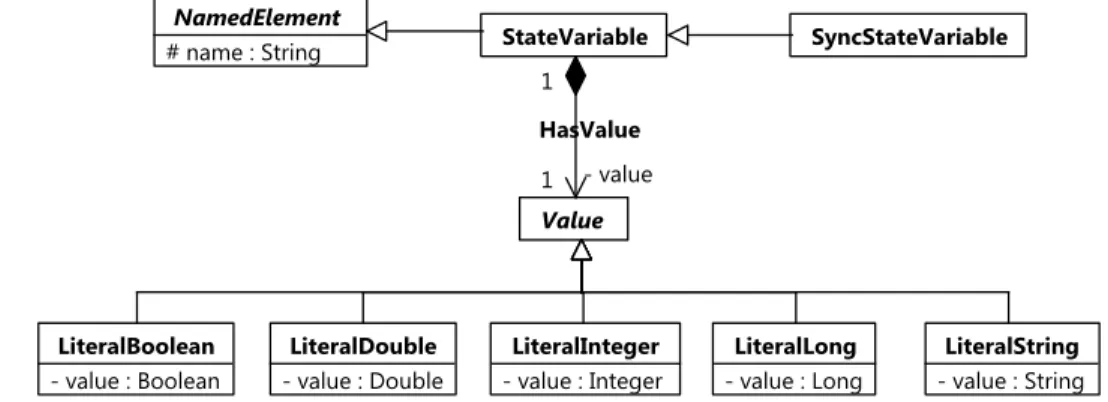
Figure 2.1: Sample TGraph schema as a UML class diagram.
Figure 2.1 shows such a schema, using the concrete syntax of UML class diagrams. It illustrates the use of generalization and composition between a set of different StateVariable and associatedValue vertices that store the value.
HasValueInstance : HasValue
Figure 2.2: Sample TGraph as a UML object diagram.
Figure 2.2 shows a possible TGraph that conforms to this schema. The graph is visu- alized by using the concrete syntax of UML object diagrams.
Graph Repository Query Language
The Graph Repository Query Language (GReQL) is a language used for retrieveing data stored as TGraphs. It was developed in the GUPRO project [8]. GReQL can be char- acterized as a schema-sensitive expression language with dynamic types. The value of a GReQL expression is precisely defined, due to the use of mathematical expressions [6]. A typical GReQL query specifies the range of free variables, poses conditions on them, and finally describes the desired output set.
The most powerful concept in GReQL are regular path expressions. A path expression describes the set of all paths that match the given pattern. Path expressions can be used to test if pairs of nodes are connected via the specified path. A path expression can be used to denote the set of vertices which can be reached from a starting vertex. Given the sample schema for a TGraph and assuming that a TGraph exists as shown in Section 2.1.1, we illustrate some common GReQL queries next.
From-With-Report Expression. A common GReQL expression that is used for most queries is the from-with-report (FWR) expression. In the from part, vertices or Edges are declared using vertex : V{VertexType}oredge : E{EdgeType}constructs respectively.
The with part expresses constraints andreport describes the output set.
1 from
2 v a r : V{S t a t e V a r i a b l e}, l i t : V{L i t e r a l B o o l e a n}
3 with
4 v a r . name = ” i s B l o c k i n g ” and
5 v a r −−>{H a s V a l u e} l i t
6 r e p o r t
7 v a r . name as ” V a r i a b l e ” , l i t . v a l u e as ” V a l u e ”
8 end
Listing 2.1: Sample GReQL query.
Listing 2.1 expresses a query that searches for all StateVariable vertices that have a name that equals ” isBlocking ”. The query returns a table with names and associated
values. In line 4, the name matching is done, and in line 6 a regular path expression is used. This expression states that there must be one edge of type HasValue between the two StateVariable and LiteralBoolean vertices.
Quantifier Expressions. GReQL also supports exists and forall quantifier expres- sions. A short example for using them to express a constraint that evaluates to a boolean value, is given in Listing 2.2. The query checks if there is an StateVariable vertex with the name” isBlocking ”and if so, it must be associated to a LiteralBoolean vertex that has the value false via an edge of type HasValue. The evaluation of this GReQL expression on the TGraph depicted in Figure 2.2 returns true.
1 e x i s t s v a r : V{S t a t e V a r i a b l e}, l i t : V{L i t e r a l B o o l e a n} @
2 v a r . name = ” i s B l o c k i n g ” and
3 v a r −−>{H a s V a l u e} l i t and
4 l i t . v a l u e = f a l s e
Listing 2.2: Sample GReQL constraint using the exists quantifier.
Graph Repository Transformation Language
There is ongoing research that focusses on the development of theGraph Repository Trans- formation Language (GReTL) [19]. GReTL is a Java API that can perform transforma- tions on TGraphs. This approach is based on schema transformations and also uses GReQL queries. In this thesis, GRAF does not make use of GReTL, but transforms the runtime model directly via a generated Java API. To achieve this, we use theJava Graph Laboratory (JGraLab). This library is discussed next.
Java Graph Laboratory
The Java Graph Laboratory (JGraLab) [9] is a Java API that supports all operations to create, manipulate and traverse TGraphs. Based on a TGraph schema, JGraLab tools can generate a Java API that can be used to create, or manipulate an object model representation of TGraphs that conform to a given schema. This schema is created using IBM’s RSA tool for modeling and is exported as an XMI file. Each vertex (UML class) and each edge (UML association) in a schema, such as seen in Figure 2.1, is represented by a set of interfaces and implementing classes with helper methods.
The example in Listing 2.3 shows, how a query can be embedded in Java and how the TGraph can be accessed and transformed. Starting in line 1, a GReQL query is defined as
a Java String that returns a single LiteralBoolean vertex from the TGraph. The GReQL helper expression theElement() is used to return the single and only value from the result set. An exception is thrown during evaluation of the expression, if the result does not meet this criteria. Lines 12-14 create a GreqlEvaluator object for the query and trigger the evaluation process. After some sanity checks, line 20 uses the generated Java interface type LiteralBoolean to hold the result. Finally, the value attribute of the LiteralBoolean vertex is accessed and modified, using the generated accessor methods.
1 S t r i n g q u e r y = ” t h e E l e m e n t (
2 f r o m
3 v a r : V{S t a t e V a r i a b l e}, l i t : V{L i t e r a l B o o l e a n}
4 w i t h
5 v a r . name = \” i s B l o c k i n g\” and
6 v a r −−>{H a s V a l u e} l i t
7 r e p o r t
8 l i t
9 end
10 ) ” ;
11
12 G r e q l E v a l u a t o r e v a l = g e t E v a l u a t o r ( q u e r y ) ;
13 e v a l . s t a r t E v a l u a t i o n ( ) ;
14 J V a l u e r e s u l t = e v a l . g e t E v a l u a t i o n R e s u l t ( ) ;
15
16 i f ( r e s u l t != n u l l && r e s u l t . i s V a l i d ( ) ) {
17 i f ( r e s u l t . i s V e r t e x ( ) ) {
18 V e r t e x v = r e s u l t . t o V e r t e x ( ) ;
19 i f ( v i n s t a n c e o f L i t e r a l B o o l e a n ) {
20 L i t e r a l B o o l e a n t y p e = ( L i t e r a l B o o l e a n ) v ;
21 System . o u t . p r i n t l n ( ” Old : ” + t y p e . i s v a l u e ( ) ) ;
22 t y p e . s e t v a l u e (t r u e) ;
23 System . o u t . p r i n t l n ( ” Changed : ” + t y p e . i s v a l u e ( ) ) ;
24 }
25 }
26 }
Listing 2.3: A GReQL query embedded in Java.
2.1.2 Source Code Annotations
Annotating source code is a common practice in different programming tasks. In its essence, it is the enrichment of source code with meta-data that can be processed by the human readers, the programmers, or even automatically by tools. Java enterprise applications and application servers, such as GlassFish [16] or JBoss AS [25], make heavy use of annotations.
For the development of GRAF, we make use of custom Java annotations for the automatic binding of the managed software application to the framework.
Java annotations are simple to develop but add the possibility to access them in com- piled Java source code (class files), or even at runtime, using Java reflection. Listing 2.4 shows the creation of a Java annotation that can be used to annotate methods. This an- notation is also readable at runtime, according to its retention policy and can be used to add a degree of resource usage to methods. In this example, the value is simply stored as a String. After importing this annotation type, programmers can use it in their Java code, such as shown in Listing 2.5.
1 @ T a r g e t ( E l e m e n t T y p e .METHOD)
2 @ R e t e n t i o n ( R e t e n t i o n P o l i c y . RUNTIME)
3 p u b l i c @ i n t e r f a c e R e s o u r c e U s a g e {
4 S t r i n g l e v e l ( ) d e f a u l t ”LOW” ;
5 }
Listing 2.4: Sample definition of Java annotation type.
1 @ R e s o u r c e U s a g e ( l e v e l =”HIGH” )
2 p r i v a t e v o i d someComplexMethod ( ) {
3 // . . .
4 }
Listing 2.5: Use of Java annotation type.
2.1.3 Aspect-Oriented Programming
When developing GRAF, we decided to useAspect-Oriented Programming AOP technology as a way to inject source code into predefined points of the software application to be managed, in order to establish a binding to GRAF automatically.
Combined with Java annotations, AOP allows to expand the Java language in a clean pluggable way rather than using annotations solely for the generation of documentation or source code. Furthermore, existing AOP languages such as AspectJ [27] or AOP frame- works, like JBoss AOP [24] hide the implementation complexity of bytecode transforma- tions involved.
Generally, all AOP frameworks define two things: a way to implement crosscutting concerns as code snippets, and a programmatic construct, a programming language or a set of tags, to specify how and where to apply those snippets of code. The terminology varies from technology to technology but in essence, the same concepts apply. Since we
decided to use JBoss AOP for the implementation of GRAF, we stick to the terminology as introduced by the JBoss AOP documents [23], available online. Subsequently, we give a brief introduction to AOP terminology, covering the most common AOP concepts.
Aspect. An aspect is a modularization of a concern that cuts across multiple objects.
Transaction management is a good example of a crosscutting concern in Java enterprise (J2EE) applications. In JBoss AOP, aspects are implemented as regular Java classes implementing specific interfaces, or as simple methods with a predefined signature.
Join Point. A join point is a point during the execution of a program, such as the beginning or ending of a method execution.
Advice. An advice is an action taken by an aspect at a particular join point. Different types of advice includearound,before and after advice. JBoss AOP models an advice as a Java class type named interceptor, and maintains a chain of interceptors around each join point.
Pointcut. A pointcut is a predicate that matches join points. An analogy to a pointcut is a regular string expression. Where such an expression is used to express string patterns, a pointcut expression matches events/points within software.
Weaving. Weaving is the process of mixing aspects with other application types or objects to create an advised object. This is usually done using bytecode transformations in Java. Weaving can be performed at compile time, load time, or at runtime. While AspectJ performs weaving at compile time only, JBoss AOP also allows weaving at load time or even at runtime. The latter is called Dynamic AOP.
2.1.4 The Session Initiation Protocol
The Session Initiation Protocol (SIP) is a text-based, IP-based protocol that is widely used for controlling multimedia communication sessions such as voice and video calls. In Chapter 5, we apply GRAF to an application from the voice over IP (VoIP) domain that relies on SIP, so we cover the basics here.
SIP can be used for i) creating, ii) modifying, and iii) andterminating two-party (uni- cast) or multiparty (multicast) sessions that consist of one or several media streams. The modification can involve changing addresses or ports, inviting more participants, and
adding or deleting media streams. SIP’s application domains include video conferenc- ing, streaming multimedia distribution, instant messaging, or online games. The protocol was designed to support the location of users world-wide. Each user is identified by a an address very similar to an email address (user@domain), where user is the user’s unique name or a (telephone) number, and thedomain is the address of a SIP-network.
SIP’s architecture is based on client/server, consisting of i) User Agent, which are endpoints of a call, and a set of servers such as the ii) Proxy Server, iii) Redirect Server, as well as iv) the Registrar Server. These are computers on the network that process request messages from clients and answer with response messages. The last three components can be installed and executed on the same computer. In the following, we give a short introduction to each components.
User Agents
The User Agent acts as a terminal for communication. Computers, telephones or mobiles are common examples. Users need to know the unique addresses of each other for making a direct call. In a SIP connection, the initiator of a session (caller) is referred to as the User Agent Client (UAC) and the agent that responds to the request (callee) is referred to as theUser Agent Server (UAS). Throughout a session, a user agent switches back and forth between these two roles, as it sends and received messages.
SIP Servers
The SIP Server resolves user names to IP addresses, so that request messages from one user agent are directed properly to another one. User agents register with a SIP server and provide them with their name and current IP address. By establishing this connection, other user agents can now check for availability and send an invitation to join a session.
The SIP server acts as the controller for such an invitation and resolved the current IP correctly. In case that an invited user agent uses a different SIP server, further requests are sent by the first server to establish a connection. According to its task, a SIP server can play one of three roles, which we discuss subsequently.
Registrar Servers. A Registrar Server receives REGISTER messages from each user agent who has logged onto the network. This message contains the SIP-address as well as the IP-address of the user. The Registrar stores this information in the Location Service, a database that is used to find users. When someone wishes to establish a session with one of the registered users, the Registrar’s information is used to resolve the current IP address of the involved users.
Proxy Servers. AProxy Server is a computer that forwards requests on behalf of other computers. If a SIP server receives a request message from a user agent, this message can be redirected to another SIP server on the network. Furthermore, a proxy server can provide additional functionality such as network access control, authentication, authorization or further security-related services.
Redirect Servers. A Redirect Server supports the Proxy Server and redirects clients to the user agent they wish to connect to. By responding with the IP address of the user agent to be contacted, a client can make the call itself directly. In addition, calls can be redirected to multiple clients by splitting the call to several locations. That way, multiple clients receive the call and the first one that accepts and answers the call receives it.
2.2 Related Approaches
There are several model-centric approaches to runtime adaptation. Some of them also utilizeAspect-Oriented Programming (AOP) techniques as well as computational reflection.
However, the granularity level at which adaptation is performed varies among them.
DiVA [12] considers design and runtime phases of adaptation. It is based on a solid four dimensional modeling approach to SASS [13]. At design time, a base model and its variant architecture models are created. The models include invariants and constraints, which can be used to validate adaptation rules. In comparison to our approach, DiVA focuses on adaptation at the architectural level, whereas we target adaptation at a lower level by incorporating methods and fields.
Vogel and Giese [40] propose a model-driven approach which provides multiple archi- tectural runtime models at different abstraction levels. They derive abstract models from the source models. Subsets of the target models focus on a specific adaptation concern to simplify autonomic managers. Similar to DiVA, this research also targets adaptation from an architectural point of view. This approach lacks from a supporting evolution process towards the instrumentation of the software application.
The Rainbow framework [5], uses an abstract architectural model to monitor the run- time properties of an executing system. It is able to perform model constraint evaluation and adaptation at runtime. Similar to our approach, certain components of Rainbow are reusable. Furthermore, the authors assume that any target system provides system access hooks for sensing and that developers can make use of wrappers to add hooks to legacy systems for affecting purposes. Guidelines for introducing such changes are not a focus of this work, though.
TRAP/J [37] is a software tool which enables the addition of new adaptable behavior to existing Java applications without requiring changes of the original source code or the virtual machine. TRAP/J utilizes behavioral reflection and AOP techniques. In this approach, developers choose a subset of existing classes, and generate a set of aspects and reflective classes for an adapt-ready software. TRAP/J focuses on the technological approach of how to make an existing Java application adaptable. TRAP/J supports sensing of method invocations but not the sensing of read or write operations on fields.
Similar to some of the presented works, our framework approach with GRAF makes use of Java reflection and AOP for the instrumentation of legacy software. In contrast to mentioned research projects, we rely on the interpretation of behavioral models for adapting the managed software application at runtime. Except for during the instrumentation phase which is always the same, we explicitly do not change the bytecode of the managed software application at runtime. Such changes are hard to verify, but by interpreting a runtime model, and by using mathematical definitions of the TGraph, the formal verification of adaptation is possible.
StarMX [3] is a generic configurable adaptation management framework. It clearly separates management logic from application logic by using explicit sensing and effecting interfaces. StarMX has no dependency on application characteristics (e.g. architecture or environment) or any particular self-* property. Designed for Java-based systems, it incorporatesJava Management Extensions (JMX) technology and is capable of integrating with various policy/rule engines.
Muztaba Fuad et al. try to inject self-organizing and self-healing properties into Java programs [34]. This approach is limited to Java byte-code transformations. The byte code is analyzed and additional code is injected to automatically recover from failures such as network or processor failure. The transformations are wrap try-catch code, in order to control the application flow in case of failure. State variables are saved at specified application checkpoints as well.
From a technological point of view, the technologies used in GRAF offer a variety of flexible and powerful ways to operate on models at runtime, including the query language GReQL [6] and the JGraLab [9] class libraries. In addition, a rich Java API can be automatically derived from the runtime model schema. This technology allows us to achieve a compact implementation of GRAF.
Chapter 3 Solution
3.1 System Architecture
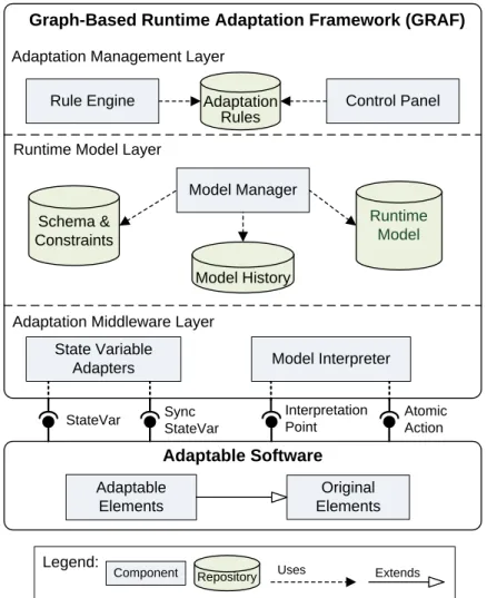
At theSoftware Technologies Applied Research (STAR) laboratory, Mehdi Amoui and the author of this thesis designed an architectural blueprint for a SASS that depends on an external adaptation framework. The results are first published in [2]. In this section, we discuss this architecture in more detail, as GRAF is an implementation of it. The main layers and components are illustrated in Figure 3.1.
The adaptable software communicates with GRAF via four different interfaces that allow data to be sent to GRAF forsensingpurposes. Furthermore, data can be manipulated and actions of the adaptable software to be invoked foreffecting purposes. We discuss the structure of the adaptable software and GRAF, as well as the connecting interfaces in more detail next. The responsibilities and tasks of each framework layer is introduced in detail, and we explain how each of them contributes to the whole architecture of a SASS.
3.1.1 Adaptable Software
In Subsection 1.1.2, we introducedmanaged software as the software that is coupled to an adaptation manager. In the context of GRAF, we refer to this software as the adaptable software. It is a version of the original, non-adaptive software, that is setup in a way so that it can be controlled by GRAF, which plays the role of the external adaptation management unit. Adaptable software can be built by migrating an existing, non-adaptable software system towards adaptability [2].
The adaptable software is causally connected to the runtime model which is encapsu- lated and managed by GRAF. This causal connection is established by an intermediate
Adaptable Elements
Original Elements Model Interpreter State Variable
Adapters
Rule Engine Control Panel
Adaptation Management Layer
Runtime Model Layer
Adaptation Middleware Layer
Model Manager Adaptation
Rules
Schema &
Constraints
Graph-Based Runtime Adaptation Framework (GRAF)
Adaptable Software
Legend:
Component Uses
Repository Extends
StateVar Sync StateVar
Interpretation Point
Atomic Action Model History
Runtime Model
Figure 3.1: A SASS that is using GRAF to achieve adaptivity.
layer, the adaptation middleware, which communicates to the adaptable software using predefined interfaces. In the following, we cover the main components and interfaces that need to be provided by any adaptable software.
Original Elements
When applying GRAF in a migration context,original elements are those software elements that already existed within the software application to be migrated towards a SASS. In the context of creating adaptable software from scratch, these elements can be thought of as used helper elements, such as classes provided by imported libraries.
Adaptable Elements
Adaptable elements are the building blocks that support a certain degree of variability to be controlled by GRAF. In a migration towards self-adaptive software, they are derived from original elements by applying refactoring steps and by exposing them via predefined interfaces to GRAF. More specifically, adaptable elements are those components and frag- ments of the legacy system that are in need for adaptation or can provide information about changes in the application’s environment.
Connecting Interfaces
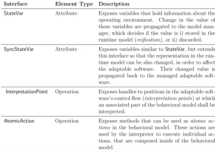
Every adaptable software element needs to provide a set of interfaces for adaptation by GRAF. In Table 3.1, these interfaces are listed, together with a brief description.
Table 3.1: Interfaces that need to be provided by any adaptable software.
Interface Element Type Description
StateVar Attribute Exposes variables that hold information about the operating environment. Change in the value of these variables are propagated to the model man- ager, which decides if the value is i) stored in the runtime model (reification), or ii) discarded.
SyncStateVar Attribute Exposes variables similar toStateVar, but extends this interface so that the representation in the run- time model can be also changed, in order to affect the adaptable software. Their changed value is propagated back to the managed adaptable soft- ware.
InterpretationPoint Operation Exposes handles to positions in the adaptable soft- ware’s control flow (interpretation points) at which an associated part of the behavioral model shall be interpreted.
AtomicAction Operation Exposes methods that can be used as atomic ac- tions in the behavioral model. These actions are used by the interpreter to execute individual ac- tions, that are composed inside of the behavioral model.
The first column describes the name of the interface, the second column denotes the type of source code element that this interface deals with in the adaptable software, and the third column contains the interface description.
3.1.2 Graph-based Runtime Adaptation Framework
The Graph-based Runtime Adaptation Framework (GRAF) acts as an external controller of the adaptable software. This is very similar to the role of the adaptation manager with regards to the managed software element, as initially sketched in Figure 1.1. In our case though, the external controller is not just an adaptation manager. GRAF encapsulates a runtime model that is specific to the adaptable software. The framework achieves adap- tivity of the adaptable software’s behavior by transforming and interpreting parts of its runtime model.
Based on the architectural blueprint that we illustrate in Figure 3.1, we introduce the tasks and responsibilities of each GRAF element (component/repository) subsequently.
These descriptions are the basis for a prototypical implementation, which is discussed later in Chapter 4.
Adaptation Middleware Layer
Theadaptation middleware layer is responsible for all possible ways of communication and interaction between the adaptable software and the runtime model layer. It provides a set of reusable components that are independent from the adaptable software.
State Variable Adapters. State variable adapters support the propagation of (changed) values from marked variables in the adaptable elements to the runtime model, by using the StateVarinterface. In addition, the SyncStateVar interface is an extension of the StateVar interface that allows to manipulate data in adaptable elements and to instantly reflect it back into the adaptable software.
Model Interpreter. GRAF’s model interpreter executes parts of the behavioral model.
These parts compose atomic actions that are available via the AtomicAction interface to describe behavior for a specific point in the adaptable application’s control flow (in- terpretation point) within adaptable elements. These predefined points are the starting points of methods that need adaptivity and hence, are exposed to the interpreter by the InterpretationPoint interface. The interpreter invokes methods of the adaptable software via the AtomicActioninterface, when executing a behavior description.
It is important to notice, that the interpreter depends on the runtime model schema, that is on the language used to express the behavioral model, because it needs to know the modeling elements and their relationships.
Runtime Model Layer
The runtime model layer is positioned on top of the adaptation middleware and contains the runtime model that is at the core of our approach to achieve adaptivity. In addition, this layer contains utility components that simplify and encapsulate necessary operations on the runtime model, such as evaluating queries or executing transformations.
Runtime Model. The purpose of the runtime model is to describe i) thestate variables with their concrete values that exists at a given point in time in the adaptable software, and ii) the behavior to be interpreted at predefined points in the control flow The state variables and the behavior descriptions of the runtime model are independent from the programming language or platform of the adaptable software.
Each atomic action that is used in the behavioral model stores some meta-data that is specific to the adaptable software’s technology, such as a fully qualified method name in Java. This information is necessary during model interpretation, to resolve an imple- mentation via theAtomicAction interface. That way, we can (re-)use existing functionality from within the adaptable software as building blocks for modeling behavior.
Together with conditions and further modeling elements, complex behavior can be modeled by composing existing methods in the behavioral model. Behavioral adaptivity is achieved by changing the behavioral model at runtime. Different modeling languages for behavior can be used, such as UML Activity Diagrams, State Charts, Petri Nets, or Feature Trees. These need to be defined by the runtime model schema though, and a specific interpreter is needed for each behavior description language. In this thesis, we use the expressiveness of UML Activity Diagrams for modeling behavior.
Schema and Constraints. The runtime model conforms to the runtime model schema, which defines the possible i) model elements and ii) relationships between them. A set of constraints can be derived from the runtime model schema, such as multiplicities for relations. In addition, further constraints can be defined (using a query language) and are stored together with the schema. These constraints describe context sensitive restrictions for all runtime models.
In addition to these constraints atschema-level, user’s of GRAF can develop constraints that are at model-level. Such constraints can be used to express:
a) Range restrictions on state variables.
b) Contracts of atomic actions (pre-/post-conditions, parameters and their value ranges).
c) Orchestration constraints for atomic actions and their (in-) compatibilities.
Both types of constraints can be used by the rule engine for its analysis and planning steps, and they may be used by the model manager to validate transformations.
Model Manager. The model manager is responsible for all tasks that are related to manipulating the runtime model. It keeps the runtime model in sync with the inner state of the application layer, exposed via the StateVar and SyncStateVar interfaces. For the purpose of loose coupling, the model manager can decide, whether to accept a change event it receives from a state variable adapter, or if it discards this data.
In addition, the model manager acts as a controller for all other types of accesses to the runtime model, and hence, it provides a set of utility objects forquerying andtransforming.
Furthermore, the model manager is responsible for the evaluation of constraints after a transformation has been applied. It can even roll back changes to the runtime model and it can inform the rule engine about this failed adaptation attempt.
Model History. The model history supports the storage of temporal snapshots of the runtime model as additional state information (history/prediction). The rule engine can access this data by querying the history repository via the model manager. That way, the rule engine can learn from its past actions by using the available history. Even the application of data mining techniques such asfrequent itemset analysis[1] could be possible, once the repository contains a representative amount of data.
Adaptation Management Layer
The adaptation management layer acts as the controller thatruns in parallel to the adapt- able software and uses a set of adaptation rules from a repository to make changes to the runtime model over time. This layer is composed of a repository with adaptation rules and a rule engine that uses its own heuristics to plan adaptation.
Rule Engine. In GRAF, the rule engine plays the role of an adaptation manager that can rationalize changes in the runtime model. It can either observe or query the runtime model in order to retrieve these changes, and it can receive more detailed information on the current, or past state of the adaptable software, by using the Model history.
After gathering all the required information for planning, the rule engine uses the set of available adaptation rules to choose a sequence of graph transformations to be executed on the runtime model via the model manager.
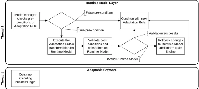
Adaptation Rules. In the context of GRAF, adaptation rules are Event-Condition- Action(ECA) rules that describeatomic adaptation tasks. The three parts of an adaptation rule are as follows:
1. Event. The event for the application of a rule occurs, whenever the runtime model changes and the rule engine needs to react. The model manager keeps track of this event.
2. Condition. The condition then is expressed by a query on the runtime model, which tests whether an adaptation rule may be applied, or not.
3. Action. The action is a graph transformation and the actual adaptation to be performed on the runtime model. A transformation has pre- and post-conditions, also expressed as queries on the runtime model. They can be evaluated by the model manager to perform further validation. That way, not necessary adaptation steps can be detected before executing the adaptation rule, and invalid model states can be identified after a transformation. In the latter case, the runtime model can be rolled back, if needed.
Control Panel. The control panel allows administrators to interact with the SASS and especially with GRAF. They can i) observe the log of adaptation steps by querying the runtime model history, ii) modify adaptation rules and model constraints, and iii) override decisions and heuristics of the rule engine. Furthermore, administrators get notified, when- ever an adaptation attempt fails or if the SASS is totally uncontrollable by the adaptation management layer.
We envision a feedback loop, where the SASS is manually adjusted at runtime (micro adaptation). If such manual runtime changes to the SASS are not possible or sufficient, some of GRAF’s components or repositories can be maintained offline and the SASS is finally restarted again (macro adaptation).
3.2 Runtime Behavior
After introducing the overall structure of GRAF, we discuss the framework’s runtime be- havior in this section. We differentiate between four major scenarios that are involved in
adapting software at runtime using GRAF. These are i)sensing, ii)controlling, iii)effecting, and iv) interpreting. The foundations of the control loop are covered in [33].
Subsequently, we give an overview on each scenario as a separate process diagram. Note, that we ignore all the possible alternate flows and exceptions that might occur during the adaptation scenarios on purpose here. The main idea is to show the control flow of GRAF under typical conditions.
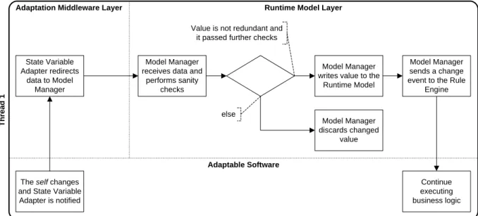
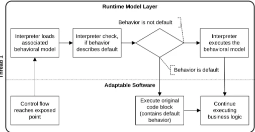
3.2.1 Sensing Scenario
The sensing scenario of GRAF involves the propagation of changed values from the adapt- able software’s inner state (self to the runtime model. This results in a notification of the rule engine in the adaptation management layer. Figure 3.2 illustrates the control flow of this scenario. It starts with a change in the adaptable software’s environment. Assuming application-level adaptation, as introduced in Subsection 1.2.2, these changes are reflected by the inner state of the adaptable software (the self) and thus, can be sensed in its variables and fields.
The self changes and State Variable Adapter is notified
Continue executing business logic State Variable
Adapter redirects data to Model
Manager
Model Manager receives data and
performs sanity checks
Model Manager writes value to the
Runtime Model
Model Manager sends a change event to the Rule
Engine
else
Value is not redundant and it passed further checks
Model Manager discards changed
value
Adaptation Middleware Layer Runtime Model Layer
Thread 1
Adaptable Software
Figure 3.2: Steps involved in the sensing scenario of GRAF.
1. A change to the adaptable software and its data happens, as the system communicates with its operating environment.
2. If the changed variable is an instrumented Java field that is exposed via theStateVar or SyncStateVar interfaces, a state variable adapter of GRAF takes care of sending the updated value to the model manager. The adaptable software’s control flow is executed concurrently.
3. The model manager in the runtime model layer receives the changed value.
4. The model manager decides if the value should be used to update the state variable representation inside the runtime model. If yes, it stores the value in the runtime model’s pool of state variables.
5. The model manager notifies the rule engine about changes, so it can start to react.
3.2.2 Controlling Scenario
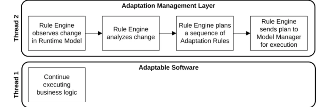
The controlling scenario of GRAF is essentially a MAPE-loop, as described in IBM’s ar- chitectural blueprint for autonomic computing [20]. The control flow of this scenario is illustrated in Figure 3.3.
Continue executing business logic
Rule Engine observes change in Runtime Model
Adaptation Management Layer
Thread 2Thread 1
Adaptable Software Rule Engine
analyzes change
Rule Engine plans a sequence of Adaptation Rules
Rule Engine sends plan to Model Manager
for execution
Figure 3.3: Steps involved in the controlling scenario of GRAF.
This scenario starts, when a change listener of the rule engine receives a change signal from the model manager. In return, the rule engine answers by passing a sequence of adaptation rules to be applied on the runtime model.
1. Monitoring. A change in the runtime model is observed by the rule engine.
2. Analysis. The rule engine analyzes the changes and possibly makes use of the runtime model and it’s change history by querying it via the model manager for a more detailed evaluation.
![Figure 1.2: Hierarchy of self-* properties, according to [38].](https://thumb-eu.123doks.com/thumbv2/1library_info/5218169.1669417/16.918.224.703.152.362/figure-hierarchy-self-properties-according.webp)