2Institut de Physique Nucle´aire, 91406 Orsay, France (Received 19 November 2009; published 11 August 2010)
EUROTRANS is a European research program for the transmutation of high level nuclear waste in an accelerator-driven system (ADS). As proposed, the driver linac needs to deliver a 2.5–4 mA, 600 MeV continuous-wave (CW) proton beam and later a 20 mA, 800 MeV one to the spallation target in the prototype-scale and industrial-scale demonstration phases, respectively. This paper is focusing on the conceptual studies performed with respect to the 17 MeV injector. First, the special beam dynamics strategies and methods, which have been developed and applied to design a current-variable injector up to 30 mA for allowing an easy upgrade without additional R&D costs, will be introduced. Then the error study made for evaluating the tolerance limits of the designed injector will be presented as well.
DOI:10.1103/PhysRevSTAB.13.080101 PACS numbers: 28.65.+a, 29.20.Ej, 29.25.Dz, 29.27.Bd
I. BACKGROUND
At present, 35% of the total electrical power in the European Union is generated by 145 reactors [1], but a public worry is how to treat the nuclear waste, especially the plutonium, minor actinides, and other long-lived fission products. Figure 1 indicates that the transmutation tech- nology could be an efficient solution to shorten the decay time of the waste greatly. Launched by the European Union, the EUROTRANS project [2] is aiming to demon- strate such transmuters in two phases: (i) to construct a 50–
100 MW (thermal) experimental facility demonstrating the technical feasibility of transmutation in an accelerator- driven system (XT-ADS); (ii) to realize a several hundred MW modular European facility for industrial transmuta- tion (EFIT).
The specifications of the required proton beams for the XT-ADS and EFIT phases are listed in TableI[3], where the most demanding requirement is that the beam trips (i.e.
the beam interruptions on the target) with duration periods
>1 shave been restricted to<20per year and<3per year for the two phases, respectively, because beam trips of this length will cause serious thermal stress and fatal damages to the subcritical core. These beam-trip limits are 2 or 3 orders of magnitude lower than typical values found with existing accelerators [4], respectively, so the primary con- cern for the design of the EUROTRANS driver linac is how to ensure such extremely high reliability.
The reference layout of the planned EUROTRANS fa- cility is schematically shown in Fig.2. Taking advantage of modular, independently phased superconducting (SC) cav- ities with wide velocity acceptance, the main driver linac has been designed to be intrinsically fault tolerant with an excellent potential for reliability [5]. In the 17 MeV in-
jector part, the beam-velocity profile is frozen by design, so that, different than the main linac, the failure of any accelerator cavity here is not able to be compensated by the neighboring cavities and will inevitably lead to a beam interruption. Therefore, in order to increase the facility reliability, it was proposed to duplicate the injector to provide a hot stand-by injection line with fast switching
FIG. 1. (Color) Comparison of the decay time of the radiotox- icity of nuclear waste to the reference level of the original uranium ore before and after transmutation [1].
*zhang@iap.uni-frankfurt.de
capabilities for relieving the main one in case of failure. In the XT-ADS phase, this two-injector scheme is only an option, and the priority has been put on the design of an ‘‘as efficient and reliable as possible’’ injector.
This paper focuses on the conceptual design studies performed for the 17 MeV injector. As shown in TableI, the required proton beam current is 2.5–4 mA in the XT- ADS phase and is 20 mA in the EFIT phase. Leaving safety margins, 5 and 30 mA have been used as the design currents for the two phases, respectively. For an easy upgrade without additional R&D costs, a special design philosophy has been developed to realize a current-variable injector (excluding details of the ion source and the low- energy beam transport section) up to 30 mA. Therefore, new beam dynamics strategies and methods are needed to control the different space-charge effects for widely vary- ing beam currents that have to be transported by the same structure.
II. INJECTOR BEAM DYNAMICS
For the EUROTRANS injector, a layout shown in Fig.3 was proposed by Frankfurt University with the following considerations: (i) Characterized by the velocity-
independent electric focusing, the radio-frequency quad- rupole (RFQ) accelerator is the standard structure for capturing, shaping, bunching, and preaccelerating a low- energy input beam. (ii) As a kind of novel SC multicell accelerator in the low- and intermediate-energy regimes, the SC cross-bar H-type drift-tube linac (CH-DTL) struc- ture (for detailed parameters see [6]) is chosen for com- pleting the main acceleration efficiently. (iii) A room- temperature (RT) CH-DTL is well suited as a transition between the above-mentioned two parts, because it cannot only provide higher real-estate gradients than the RFQ but also ‘‘filter out’’ the transported, off-energy particles from the RFQ to avoid losses at higher energies in the SC cavities that would create radiation and superconductivity failure problems.
A. Radio-frequency quadrupole: 0.05–3.0 MeV Standing at the beginning of the driver linac, the RFQ has a decisive influence on the performance of the whole machine. For the choice of its initial parameters the follow- ing ideas have been implemented: (i) The 0.05 MeV input energy is a trade-off of RFQ length, ion source technology, and space-charge effects for both beam currents, while the TABLE I. Specifications of the required proton beams for XT-ADS and EFIT [3].
Phase
Parameter XT-ADS EFIT
Peak beam intensity [mA] 2.5–4 20
Output beam energy [MeV] 600 800
Beam-trip number (>1 s) <5per three-month operation cycle <3per year
Beam stability Energy:1%; intensity:2%; size:10%
Beam time structure CW, with200szero-current holes
FIG. 2. (Color) The reference layout of the planned EUROTRANS facility [17].
3 MeV output energy leads to a reasonable geometry of the shortest drift tube for the CH-DTL structure at 352 MHz.
(ii) An equal input normalized rms transverse emittance, 0:2mm mrad, is used for both 30 and 5 mA. This emit- tance value is conservative for such currents (see [7]). (iii) In order to keep the peak surface electric field below 1.7 times the Kilpatrick limit for avoiding sparking as well as to provide a reasonable accelerating gradient and sufficient transverse focusing for beam currents up to 30 mA, an intervane voltage of 65 kV has been adopted.
Based on these modest and compromising choices, the EUROTRANS RFQ was designed following an unconven- tional approach, the so-called new four-section procedure (NFSP) [8]. Compared with the traditional Los Alamos National Laboratory (LANL) four-section procedure [9], the NFSP approach can be distinguished by the following features: (i) Unlike the LANL method which holds the transverse focusing strengthB simply constant, the NFSP approach variesBaccording to the changing space-charge situation along the RFQ: namelyBis first rising to balance the stronger and stronger transverse defocusing effects caused by the longitudinal compression until they begin to be weakened by the gradually increased beam velocity;
afterwardsBis accordingly reduced to avoid longitudinal emittance growth until the beam is well bunched; and finallyBwill be held constant when the main acceleration starts. In case of using a constant intervane voltage, the desiredBprofile can be achieved by properly varying the midcell electrode aperturer0along the RFQ. (ii) The beam bunching process is divided into three sections: (1) the initial section makes a gentle increase in electrode modu- lationmwhile the synchronous phase’sis kept at90so that the ‘‘pushed’’ prebunching adopted by the traditional method can be replaced by a soft and symmetric prebunch- ing with a 360phase acceptance, which will eliminate an important source of particles with unstable motions; (2) in the main-bunching section, m and ’s increase quickly;
(3) finally, there is a mixed section for completing the bunching finely together with acceleration, in which m and’s are still increasing, but slower. During the whole process, the transverse and longitudinal forces are always balanced, so good beam quality can be achieved. (iii) All transitions between the neighboring sections are smoothed.
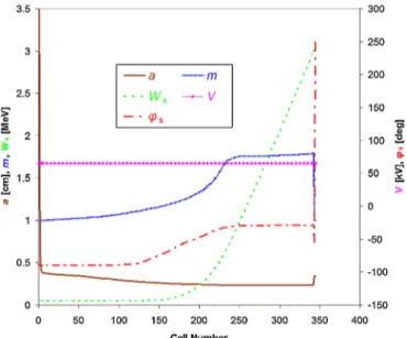
Taking into account the space-charge effects at both design currents, the NFSP-style design for the EUROTRANS RFQ varies the main dynamics parameters
in a way as shown in Fig. 4, where a is the minimum electrode aperture, m the electrode modulation, V the intervane voltage,Ws the synchronous energy, and’sthe synchronous phase.
In Fig. 4, one can notice that in the last two cells, the synchronous phase jumps to54and 250, respectively, while the electrode modulation falls down back to 1. These are the results of the performed matching between the RFQ and the CH-DTL by introducing two transition cells [10]:
(1) the first one, also known as the Crandall cell [11], makes a smooth transition from a full modulation (m >
1) to no modulation (m¼1) to end the RFQ vane tips with quadrupole symmetry; (2) the second one, which keeps m¼1, changes the orientations of the transverse phase- space ellipses with an invariant beam energy.
Without these transition cells, the major axes of the two transverse phase-space ellipses at the RFQ exit are not parallel but cross each other because the beam is focused in one transverse plane and defocused in the other one. To transport such a beam into the subsequent CH-DTL using triplets and solenoids for transverse focusing, usually a matching lens is needed to make the transverse particle distributions similar first. By contrast, the transition-cell matching method is more efficient, because: (1) for a low- velocity beam, the velocity-independent electric focusing is much stronger than the magnetic force; (2) the drift
FIG. 4. (Color) Main dynamics parameters along the RFQ.
FIG. 3. (Color) The schematic diagram of the proposed layout for the EUROTRANS injector.
space between the RFQ and the CH-DTL can be consid- erably shortened, which is also favorable for improving the beam dynamics.
Using 105 input macroparticles, the beam transport simulation of the EUROTRANS RFQ has been performed by PARMTEQM [10]. For both 5 and 30 mA, an identical RFQ geometry and an equal-area input particle distribution have been used. The only difference is that the shapes and the orientations of the input emittance ellipses have been slightly modified for each case due to proper matching (see Fig.5).
The simulation results are satisfying. At 5 mA, only one particle was lost at cell 259 longitudinally; while at 30 mA, though the space-charge effects are much stronger, only 0:1%of particles were lost and most of them had ener- gies lower than 1.5 MeV (see Fig.6), much lower than the threshold energy Eth¼2:16 MeV of the 65Cuðp; nÞ65Zn reaction, the onlyðp; nÞreaction existing below 3 MeV for a copper accelerator. In both cases, therefore, these beam losses will lead to no activation risk.
In Fig. 7, the output particle distributions are plotted, where the red and green ellipses are containing 99% and 95% of transported particles, respectively. One can see that: (1) all these distributions are very concentrated;
(2) in the transverse planes, the corresponding distributions are similar to each other for both currents; (3) the 5 mA output beam has a larger energy spread than the 30 mA one. The last phenomenon can be explained as follows: the space-charge effects in a 30 mA beam are much stronger than those in a 5 mA beam so that they can make a larger cancellation of the external bunching forces, which leads to a slower and gentler bunching process and consequently a smaller energy spread. Obviously, this is a natural problem for using an identical RFQ structure to work with two different beam currents. In principle, it is impossible to be solved by the RFQ itself, so other optimizations will be needed to improve this in the CH-DTL part.
B. Cross-bar H-type drift-tube linac: 3.0–17.0 MeV Combined with the KONUS beam dynamics concept [12], room-temperature and superconducting CH-DTL structures have been adopted to continue the beam accel- eration to 17 MeV. Similar to the RFQ case, many con- servative choices have been made: (i) For one cavity, the acceleration efficiency scales as the inverse of the ratio between the number of conventional rebunching gaps and the number of 0 synchronous phase gaps used by the KONUS dynamics. Typically, the ratio of Ngap;neg=Ngap;0
is between 0.25 and 0.5, and the EUROTRANS CH-DTL adopted a value0:4. (ii) Concerning the transverse focus- ing elements, up to 1.3 T RT quadrupole lenses and 4–12 T SC solenoids can be used [13]. For EUROTRANS, 1:2 T and5 T were chosen for the warm and cold lenses, respectively. (iii) In Fig. 8, the red-dotted curve shows the measured unloaded Q0 value of the SC CH- prototype cavity as a function of the accelerating gradient Ea, and the star marks the choice of Ea for the EUROTRANS SC CH cavities, 4 MV=m, which is very modest comparing with the achievable7 MV=m.
In the CH-DTL design, the beam dynamics especially in the longitudinal direction is very difficult in the following two regions: (i) The RFQ-DTL transition, which has to leave a0:5 m-long drift distance for housing steerer and diagnostic devices; (ii) the RT-SC transition, which needs to reserve more drift space, 1 m, for the cryomodule, helium vessel, tuner, and solenoids.
As a solution, two 2-gap rebunching cavities so-called RB-1 and RB-2 have been introduced in the above- mentioned regions, respectively. The synchronous phases of all gaps in both rebunching cavities were fixed at90 so that RB-1 and RB-2 can make the most of the rf power to minimize the energy spread of the beam but will not change the synchronous energy of the beam. This opens an option to tune the gap voltages (the bunching strengths) of these rebunching cavities for adapting to different beam FIG. 6. (Color) The lost-particle distribution at 30 mA.
FIG. 5. (Color) Input emittance ellipses for 5 and 30 mA.
currents by only adjusting the rf amplitudes, without influ- ence on the cavity structure. As mentioned in the last section, the 5 mA beam has a relatively larger energy
spread at the RFQ exit, so it needs higher gap voltages in the rebunching cavities for compensation.
Following these design principles, a current-variable CH-DTL has been designed for the EUROTRANS injector.
FIG. 7. (Color) RFQ output distributions with the red and green ellipses including 99% and 95% of transported particles, respectively (top: 5 mA; bottom: 30 mA).
FIG. 8. (Color) UnloadedQ0 value (measured at 4.4 K) of the SC CH-prototype cavity as a function of the accelerating gra- dient Ea and the choice of Ea for the EUROTRANS SC CH
cavities [18]. FIG. 9. (Color) Main dynamics parameters along the CH-DTL.
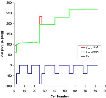
The configurations of the effective gap voltages Veff and the synchronous phases’salong the beam axis are shown in Fig.9, where: (1) the’s curve is marked in blue with
’s¼ 90 for the rebunching cavities, ’s¼ 40 for the rebunching sections inside the CH-DTL cavities, and
’s¼0for most accelerating cells; (2) theVeff curves are marked in red and green for 5 and 30 mA, respectively.
Using the RFQ output particle distributions as the input distributions, the beam transport simulation of the designed CH-DTL has been performed with theLORASRcode [14]
for the two currents, respectively. In both cases, no beam loss has been observed.
C. End-to-end design results
Scaled in length, the layout of the designed 11:4 m-long EUROTRANS injector is shown in Fig.10. Compared with the originally proposed one (see Fig.3), the planned first magnetic lens between the RFQ and the RB-1 cavity has been removed due to the per- formed transition-cell matching.
For both current cases, the 100% transverse beam enve- lopes along the injector are plotted in Fig.11, where the outermost pair of black curves represents the metal boundaries (the midcell electrode aperture of each cell for the RFQ or the inner apertures of the drift tubes and the transverse focusing elements for the CH-DTL) for the
beam transport. Clearly, the envelopes, which are marked in red and green for 5 mA and 30 mA, respectively, are quite similar throughout the accelerating channel. This also exhibits the good current adaptability of the designed injector.
In Fig. 12, the end-to-end emittance evolutions are compared between the two current cases. Along the whole injector, all transverse and longitudinal emittances are well controlled, except the longitudinal emittance of the 30 mA beam, which has two growth peaks in the rear part of the RFQ. A further study tracing all particle trajectories shows that the peaks are caused by a few off-energy particles, with a total share of less than 0.1%. After these particles have been lost, the 30 mA longitudinal emittance curve returns to normal. In the CH-DTL, the transverse and longitudinal emittance growths are all less than 10% at 5 mA; while at 30 mA, they are 30%, 34%, and 36%, respectively.
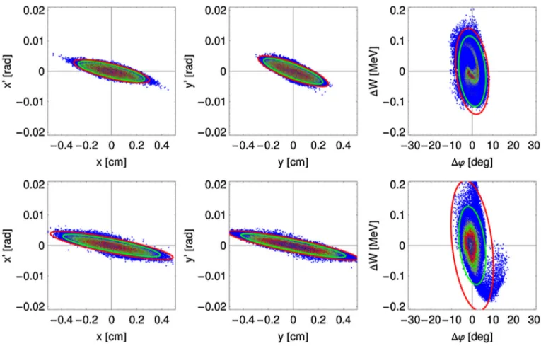
The particle distributions at the exit of the injector for both 5 and 30 mA are shown in Fig.13, where the red and green ellipses are containing 99% and 95% of transported particles, respectively. It is seen that the orientations in each plane are essentially the same. To make a quantitative comparison between these distributions and those at the RFQ output (see Fig.7), the so-called halo parameters have been calculated using the following formula (1) from [15]
and given in TableII:
FIG. 10. (Color) The designed layout of the EUROTRANS injector, where triplets and solenoids are marked in yellow and green, respectively.
FIG. 11. (Color) 100% transverse beam envelopes along the
injector (positive:xplane; negative:yplane). FIG. 12. (Color) End-to-end emittance growths.
TABLE II. Main design and simulation results of the injector.
Beam current [mA]
Parameter
5 mA 30 mA
Frequency [MHz] 352
Input/output energy [MeV] 0:05=17:0
Total structure length [m] 11.4 (RFQ: 4.3, CH-DTL: 7.1)
"trans;norm;rms
in [mm mrad] 0.20
"x;norm;rmsout [mm mrad] 0.21 (RFQ)
0.22 (DTL)
0.21 (RFQ) 0.27 (DTL)
"y;norm;rmsout [mm mrad] 0.20 (RFQ)
0.22 (DTL)
0.20 (RFQ) 0.27 (DTL)
"z;norm;rmsout [mm mrad] 0.27 (RFQ)
0.30 (DTL)
0.22 (RFQ) 0.31 (DTL)
Halo parameterHout;x 0.20 (RFQ)
0.20 (DTL)
0.29 (RFQ) 0.57 (DTL)
Halo parameterHout;y 0.18 (RFQ)
0.20 (DTL)
0.29 (RFQ) 0.58 (DTL)
Halo parameterHout;z 0.95 (RFQ)
1.05 (DTL)
1.32 (RFQ) 3.21 (DTL)
Beam transmission efficiency [%] 100 99.9
FIG. 13. (Color) Particle distributions at the injector exit with the red and green ellipses for 99% and 95% of transported particles, respectively (top: 5 mA; bottom: 30 mA).
H
ffiffiffiffiffiffiffiffiffiffiffiffiffiffiffiffiffiffiffiffiffiffiffiffiffiffiffiffiffiffiffiffiffiffiffiffiffiffiffiffiffiffiffiffiffiffiffiffiffiffiffiffiffiffiffiffiffiffiffiffiffiffiffiffiffiffiffiffiffiffiffiffiffiffiffiffiffiffi 3hq4ihp4i þ9hq2p2i212hqp3ihq3pi p
2hq2ihp2i 2hqpi2 15 7 ; (1) whereqandpare the spatial and momentum coordinates, respectively. It is seen that: (1) for the 5 mA beam, the halo parameters at the entrance and the exit of the CH-DTL are very close to each other in all planes, which indicates that
almost no halo development occurs during the beam ac- celeration; (2) for the 30 mA beam, the halo parameters are increased by a factor of 2 or 2.4 in the transverse and longitudinal planes, respectively, which is not only because the space-charge effects are much stronger in this case but also because the magnetic lenses in the CH-DTL have been mainly optimized for the 5 mA beam.
FIG. 14. (Color) Illustration of the RFQ and CH-DTL errors applied to the injector by examples (see TableIIIfor descriptions of the errors).
the CNRS simulation, and the beam size is developing stably within the range of 12 mm throughout the main linac, which is very similar to the situation in the CH-DTL.
Besides, the emittance growths also remained small (about 5% in the worst plane). The design and simulation for the 30 mA, 800 MeV main linac are in preparation.
III. INJECTOR ERROR STUDY
Construction and operation errors are inevitable in real- ity, and they play very important roles in the contribution to beam quality deterioration as well as to particle losses. In the SC part, lost particles will transfer power to the helium- cooled accelerating structures and increase the helium consumption. Even worse, if the amount of this power is too large, a quench could be caused. Therefore, the error study is crucial to evaluate the error tolerance limits of the obtained design, in particular for the EUROTRANS project, which requires extremely high reliability.
Based on a comprehensive consideration of the capa- bility of the simulation codes, the degrees of influence of errors, and the attainable precision in manufacture and operation, two kinds of representative RFQ errors, i.e., beam offset in the injection plane (BOFF) and intervane voltage error (VERR), as well as four kinds of important CH-DTL errors, i.e., transverse lens offset (QOFF), lens rotation error (QROT), tank/gap voltage error (VERR), and tank phase error (PERR), were checked for the designed EUROTRANS injector. In Fig.14, the involved errors are illustrated, and in TableIII, the error settings are given with
errors are Gaussian distributed and truncated at the 2 width within the given limits). (iii) Setting A adopts the typical ranges for the CH-DTL errors, and setting B en- larges the limits for the lens errors by a factor of 2.
For each beam current, therefore, there are six cases to combine the errors. In every case, a batch simulation consisting of totally 100 runs with different generated error distributions has been performed. The evolutions of the beam transmission efficiencies along the injector for all runs are plotted in Fig.14, where the left and right plots are for setting A and setting B, respectively, and the top, middle, and bottom plots are for Uvane¼ 5:0%, 0%, andþ5:0%, respectively.
The middle group in Fig.15assumes no RFQ intervane voltage errors to be present. With setting A, the situation is similar to the design case, and no beam loss happens in the CH-DTL. With setting B, no obvious losses appear at 5 mA, and only 5% of runs have 0.01%–1% CH-DTL beam losses at 30 mA. As can be seen by the overlaid injector schematics shown in every plot, almost all these losses are occurring outside the superconducting cavities.
The other two groups show fairly similar loss profiles as the middle group, except a lower RFQ intervane voltage will cause more losses in the RFQ and a higher one can even reduce the losses. Obviously, one should keep the RFQ intervane voltage equal to or slightly higher than the design value in the real operation so that hands-on main- tenance is feasible in the RFQ part. Therefore, the middle and bottom groups are of more practical interest. For these two groups, the beam transport is very safe throughout the TABLE III. Error settings for the injector.
Error setting
Error type
A B Error description Error
generation
RFQ
BOFF [mm]
Xbeam, Ybeam
0.2 Beam offset in the injection plane Fixed VERR
[%] Uvane
5:0, 0.0, þ5:0
Intervane voltage amplitude error Fixed
DTL
QOFF
[mm] Xlens 0:1 0:2 Transverse offsets of quadrupole
and solenoid lenses Random
QROT [mrad]
’x;y,
’z 1:5,
2:5 3:0,
5:0 Rotations of quadrupole and
solenoid lenses Random
VERR [%]
Ugap, Utank
5:0,1:0 Tank (gap) voltage amplitude error Random PERR
[] tank 1:0 Tank phase error Random
CH-DTL when the CH-DTL errors are within the typical ranges. In case of enlarging the ranges for the introduced lens errors by a factor of 2, three ‘‘bottlenecks,’’ namely the 3rd triplet, the 2nd solenoid, and the 4th solenoid, can be noticed, especially for the 30 mA beam which has much stronger space-charge effects.
Further studies have been made to improve the above- mentioned critical lenses for adapting to the large errors.
By properly enlarging their inside radii (the 3rd triplet:
from 1.5 to 1.75 cm; the 2nd solenoid: from 2 to 2.50 cm;
and the 4th solenoid: from 2 to 2.75 cm), the maximum beam loss ratio in the CH-DTL was decreased from 1% to 0.03%. Then with an increased focusing strength of the 4th solenoid from 4.75 to 5 T, all losses disappeared. In this way, cavity activation and superconducting failure prob- lems induced by beam losses will be avoided in the CH- DTL even including the errors much larger than the figures which can be achieved in practice. If applying the new FIG. 15. (Color) Beam transmission evolutions in the presence of errors (left: setting A; right: setting B; top:Uvane¼ 5%; middle:
Uvane¼0; bottom:Uvane¼ þ5%).
growth, which is defined by "addi ð"errorDTLout
"nominalDTL outÞ="nominalDTL in, has been calculated for all cases.
For most runs, the additional rms emittance growths are 20%at 5 mA or40%at 30 mA. Therefore, the beam quality of the output beam from the injector is still staying good in the presence of errors.
So far, no orbit correction has been implemented into the error study, but the space for steerer is already reserved in the design. Therefore, the error tolerances for the designed injector can be further relaxed once the steerer is taken into account.
IV. CONCLUSIONS
Taking advantage of a series of unconventional strat- egies and methods, such as the NFSP RFQ design ap- proach, the transverse matching technique without external focusing lenses between the RFQ and the CH- DTL, the KONUS beam dynamics concept, and the appli- cation of’s¼ 90rebunching cavities, an efficient in- jector has been designed for the EUROTRANS driver linac.
This injector design has the following features: (i) Conservative parameter choices and derated accelerator components, e.g., the peak surface electric field in the RFQ is below 1.7 times the Kilpatrick limit and the accel- erating gradients of the SC CH-DTL cavities are only 4 MV=m, which enhance the reliability. (ii) Short layout length and low number of components which reduce the costs (also for the duplication of the injector) as well as increase the reliability. (iii) Low beam losses. Systematic error studies performed with respect to the designed in- jector show that even in the presence of errors much larger than the typical values, the beam losses in the CH-DTL can be avoided under the proposed guideline for operation, namely, to keep Uvane0. This will help not only overcome superconductivity failure but also avoid cavity activation, allowing high reliability and hands-on mainte- nance. (iv) Good beam quality. It provides a good starting point for the subsequent main linac. (v) Current variability up to 30 mA. This enables an easy upgrade from the XT- ADS phase to the EFIT phase without additional R&D costs for the injector.
As a milestone, this injector design has been officially adopted as the reference design by the EUROTRANS project. It is foreseen that the work will be continued with an optimization of the magnetic lenses for the 30 mA case and completer error studies based on new developments of the simulation tools.
[1] The European Technical Working Group on ADS, ‘‘A European Roadmap for Developing Accelerator Driven Systems (ADS) for Nuclear Waste Incineration,’’ ENEA (2001), ISBN 88-8286-008-6.
[2] http://nuklear-server.ka.fzk.de/eurotrans/.
[3] J.-L. Biarrotte, in Proceedings of the 18th Meeting of the International Collaboration on Advanced Neutron Sources, Dongguan, Guangdong, China, 2007, pp. 336–
343 [http://www.ihep.ac.cn/english/conference/icans/
proceedings/indexed/copyr/49.pdf].
[4] N. Pichoff et al., in Proceedings of the 7th European Particle Accelerator Conference, Vienna, 2000 (EPS, Geneva, 2000), pp. 2049–2051.
[5] J-L. Biarrotteet al., inProceedings of the 23rd Particle Accelerator Conference, Vancouver, Canada, 2009(IEEE, Piscataway, NJ, 2009), TU2RAI02.
[6] H. Podlechet al.,Phys. Rev. ST Accel. Beams10, 080101 (2007), pp. 1–36.
[7] R. Gobin et al., in Proceedings of the 8th European Particle Accelerator Conference, Paris, 2002 (EPS-IGA and CERN, Geneva, 2002), pp. 1712–1714.
[8] C. Zhanget al.,Nucl. Instrum. Methods Phys. Res., Sect.
A586, 153 (2008).
[9] T. P. Wangler,Principle of RF Linear Accelerators(John Wiley and Sons, Inc., New York, 1998), p. 241.
[10] K. R. Crandall, LANL Internal Report No. LA-UR-96- 1836, revised 2005.
[11] K. R. Crandall et al., in Proceedings of the 17th International Linear Accelerator Conference (LINAC94), Tsukuba, Japan, 1994(KEK, Japan, 1994), pp. 227–229.
[12] U. Ratzingeret al., Nucl. Instrum. Methods Phys. Res., Sect. A415, 229 (1998).
[13] R. Tiedeet al., in Proceedings of the 42nd ICFA Advanced Beam Dynamics Workshop on High-Intensity, High- Brightness Hadron Beams, Nashville, Tennessee, 2008, pp. 223–230 [http://cern.ch/AccelConf/HB2008/papers/
wgb11.pdf].
[14] R. Tiede et al., in Proceedings of the 10th European Particle Accelerator Conference, Edinburgh, Scotland, 2006 (EPS-AG, Edinburgh, Scotland, 2006), pp. 2194–
2196.
[15] C. K. Allen et al., in Proceedings of the 19th Particle Accelerator Conference, Chicago, Illinois, 2001 (IEEE, Piscataway, NJ, 2001), pp. 1732–1734.
[16] J.-L. Biarrotteet al., EUROTRANS WP1.3 Final Report No. IP-EUROTRANS/DM1/WP1.3/Task 1.3.5/
Deliverable 1.74, 2010, pp. 33–34.
[17] H. Podlech et al., in Proceedings of the International Topical Meeting on Nuclear Research Applications and Utilization of Accelerators in Vienna, Austria, May 2009 (International Atomic Energy Agency, Vienna, Austria, 2010), AT/INT-03.
[18] H. Podlech, Habilitationsschrift (Frankfurt University, Germany, 2008).