geometries for different high power applications are under development at present. One cavity (f¼ 325 MHz,¼0:16, seven cells) is currently under construction and studied with respect to a possible upgrade option for the GSI UNILAC. Another cavity (f¼217 MHz,¼0:059, 15 cells) is designed for a cw operated energy variable heavy ion linac application. Furthermore, the EUROTRANS project (European research program for the transmutation of high level nuclear waste in an accelerator driven system, 600 MeV protons, 352 MHz) is one of many possible applications for this kind of superconducting rf cavity. In this context a layout of the 17 MeV EUROTRANS injector containing four superconducting CH cavities was proposed by the Institute for Applied Physics (IAP) Frankfurt. The status of the cavity development related to the EUROTRANS injector is presented.
DOI:10.1103/PhysRevSTAB.13.041302 PACS numbers: 29.20.Ej, 28.65.+a
I. SUPERCONDUCTING CH CAVITIES IN HIGH POWER PROTON AND ION ACCELERATORS International projects with high requirements regarding beam power and quality ask for new linac developments. In this context the superconducting crossbar-H-mode (CH) cavity has been investigated for several years at the Institute for Applied Physics (IAP) of Frankfurt University [1]. This kind of cavity is particularly suitable for international high power applications with intense beam currents like the EUROTRANS [2] project because its well designed multicell geometry reduces the number of drift spaces between the cavities significantly compared to conventional low-ion linacs [3]. Furthermore, the super- conducting CH structure delivers a better efficiency at high duty cycles in comparison with room temperature cavities.
Most of the CH as well as interdigital-H-mode (IH) cav- ities are operated with the special KONUS (combined zero degree structure) beam dynamics, which decreases trans- verse rf defocusing effects and enables long lens free acceleration sections [1,4,5]. Compared to conventional beam dynamics methods, in KONUS dynamics the accel- eration, the longitudinal as well as the transverse focusing, are separated. A typical KONUS period consists of three sections: (i) main accelerating section with synchronous phase’s¼0; (ii) transversal focusing element (quadru- pole triplet or solenoid); (iii) rebuncher section with’s 35for longitudinal focusing. Additionally, CH cavities can also be operated with the equidistant multigap struc- ture (EQUUS) beam dynamics concept [6]. All these men- tioned components lead to high real estate gradients and to compact linear accelerators.
A 19-cell, 360 MHz superconducting prototype CH cavity has been developed and tested at the IAP [7].
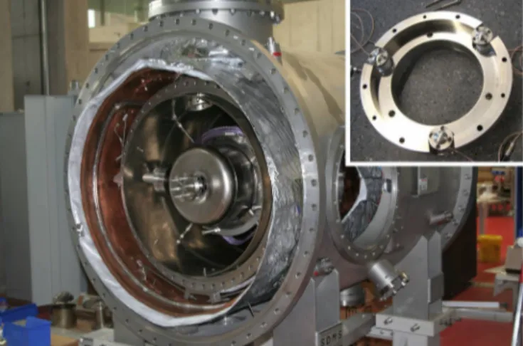
Gradients of7 MV=m, corresponding to an effective volt- age gain of 5.6 MV, were reached [8]. In the framework of the high intensity pulsed proton injectors (HIPPI) research program, a tuning system pushing the cavity end cells has been developed [9]. After several vertical measurements, the cavity has been prepared for tests in a horizontal cryomodule (see Fig.1). In the first step, a frequency shift of 400 kHz was achieved with the slow tuner as expected [10]. In the next step the fast tuner system was tested. The tuning device, based on three piezo elements mounted in a socket ring, pushes one cavity end cell while the other end
FIG. 1. (Color) 360 MHz prototype CH cavity implemented in the horizontal cryomodule with a picture of the piezo tuning device.
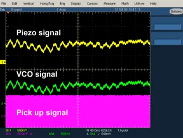
is fixed. This kind of tuning system leads to a change in capacitance and finally to a frequency shift. It is supposed to act against microphonics, Lorentz force detuning and fast pressure variations during operation. After the cavity was cooled down to 4 K, a phase difference between generator and cavity signal caused by microphonics could be measured with a phase detector. This phase difference is directly proportional to a frequency deviationf.
Finally, the voltage of a voltage controlled oscillator (VVCO), which is proportional tof andas well, was used to drive the piezo tuning device. Depending on this voltage the piezos change their length and deform the cavity. This results in a compensation of the frequency deviation shown by the constant field level of the pickup signal (see Fig.2).
Encouraged by these promising results, a new prototype designed for high power applications was proposed (see Fig. 3). This new cavity, operated at 325 MHz with a design beta of 0.16, consists of seven cells and is presently under construction at Research Instruments (RI) GmbH, Bergisch Gladbach, Germany. It will be equipped with all necessary auxiliaries like power couplers, tuning systems, and helium vessel. The frequency is the third harmonic of the UNILAC at GSI. To demonstrate the cavity capabilities under realistic accelerator environments, it will be tested in a horizontal cryomodule together with two superconduct- ing solenoids. In addition, it is planned to test the cavity in 2012 at full rf power with a 10 mA, 11.4 AMeV uranium beam delivered by the UNILAC. In Table I the main parameters of the new cavity layout are summarized.
To fulfill the requirements for high power operations, the geometry of the new CH cavity has been optimized. The main changes compared to the first CH prototype are:
(i) optimized stem geometry; (ii) inclined end stems;
(iii) additional flanges at the tank caps for cleaning proce- dures; (iv) two bellow tuners inside the cavity; and (v) port for large power coupler due to beam operation.
The stem geometry has been optimized, respectively, to the peak fields and to accommodate a sufficiently large power coupler into the girders. Inclined stems at the end cells lead to a very homogeneous field distribution along the beam axis because their new orientation increases the inductance as well as the electric field in this area [11]. A comparison of the electric field distribution for straight and inclined end stems is shown in Fig.4. This kind of end cell variation reduces the longitudinal dimensions of the cavity by about 20%–25%, as an extended end drift tube is not needed in that case for field flattening. Using inclined end stems has also great advantages in terms of the beam dynamics of high intensity linacs: A reduction of the drift tube lengths between neighbored drift tube sections is causing a reduced growth of the bunch length and an increased longitudinal phase space acceptance of the linac.
For a comparison, the first 360 MHz prototype CH cavity FIG. 3. (Color) Design of the superconducting 325 MHz CH cavity.
TABLE I. Main parameters of the 325 MHz CH cavity.
Material Bulk niobium
0.16
Frequency MHz 325.224
Total length mm 505
Cavity diameter mm 352.6
Accelerating cells 7
Ea (definition) MV=m 5
Ep=Ea 5.1
Bp=Ea mT=ðMV=mÞ 13
G 64
Ra=Q0 1248
RaRs k2 80
FIG. 2. (Color) Test of the piezo tuning system compensating frequency changes at 4 K.
had half drift tube lengths of 131 mm, while in the actual 325 MHz CH-cavity design, with inclined end stems, this length was shortened to 46 mm.
The disadvantage of inclined end stems is an increased magnetic peak field. Experiences with the first supercon- ducting prototype cavity showed that an intensive surface preparation is essential for the performance of the cavity.
Therefore, the flanges at the tank caps provide a promising way to process the cavity surface with buffered chemical polishing and high pressure rinsing.
The cavity tuning will be done by capacitive tuners welded into the girders between the stems to reach the design frequency, which will be controlled during the fabrication and adapted accordingly. For that reason the 325 MHz CH cavity will contain four static tuners with cylindrical geometry. Their height will be fixed after the frequency adjustment. To calculate their influence inside the cavity, rf simulations have been performed. Figure 5
prototype cavity [7]. Additionally, two dynamic bellow tuners are provided reaching a tuning range of several hundred kHz. One tuner will be driven by a piezo element to compensate limitations like microphonics, Lorentz force detuning, etc., during beam operation. The other one, driven by a step motor, will act as a slow tuner to readjust frequency changes and pressure effects at 4.2 K. By using these bellow tuners, the required longitudinal space for cavity installation will be minimized in contrast to a tuner system pushing on the end cells. In order to estimate the frequency gainf=hof the dynamic tuners, the height of the static ones was kept constant while increasing the bellow tuners continuously. Table IIshows that at a point of approximately 53 mm tuner height a shift of 150 kHz=mmis achievable for both bellow tuners, which is sufficient for tuning during beam operation.
To analyze their mechanical behavior, several static structural simulations have been carried out where a bellow tuner model was exposed to a range of static forces. The three-dimensional contour plot of Fig. 6 illustrates the deformation of the seven segmented tuner after pushing on the central stem with a force of up to 450 N (top) and the deformation of the tuner depending on the lateral force (bottom). The maximum effect appears at the segment on top of the tuner while the first segment was fixed. In addition to the structural simulations, a bellow tuner pro- totype of niobium with one and a half segments was built and mechanically tested. Figure 7shows the results from measurements at room temperature in comparison to the simulated values. Because of welding seams, which could not be considered in the simulations, the measured tuner deformation is approximately 3 times bigger.
At IAP Frankfurt and in cooperation with GSI and Helmholtz Institute Mainz (HIM), the design effort for a cw operated heavy ion linac has started. This dedicated linac will be applied to nuclear chemistry and to the production of super heavy elements especially. It has to provide ion beams with a mass-to-charge-ratio (A=q) up to 6 and energies up to 7.3 AMeV. Above an energy of 3.5 AMeV the linac is energy variable. Because of the required cw operation the main linac will be superconduct- ing. The front end will consist of the existing high charge injector (HLI) (108.48 MHz, 1.4 AMeV) which is presently being upgraded for the corresponding duty cycle. The main FIG. 5. (Color) Simulated tuning range of the four static tuners.
FIG. 4. (Color) Simulation of the electric field distribution for different end stem geometries.
FIG. 8. Preliminary layout of the 217 MHz CH cavity for the cw heavy ion linac for an injection energy of 1.4 AMeV.
FIG. 6. (Color) Structural ANSYS simulation of a bellow tuner model (top) and deformation of the bellow tuner depending on several forces (bottom) [17].
FIG. 7. (Color) Bellow tuner prototype of niobium with one and a half segments (left) and related results from measurements at room temperature in comparison to the simulations (right).
TABLE III. Parameters of the first superconducting CH cavity for the heavy ion linac.
0.059
Frequency MHz 217
Total length mm 689
Cavity diameter mm 413
Accelerating cells 15
Ea MV=m 5.1
Ep=Ea 5.4
Bp=Ea mT=ðMV=mÞ 5.5
G 52
Ra=Q0 3394
RaRs k2 176
acceleration of approximately 35 MV will be done by a superconducting CH linac of nine cavities operated at 217 MHz.
The first superconducting CH cavity (shown in Fig.8) of the main linac is currently under design and will be based on the EQUUS beam dynamics concept. It is planned to test the cavity with beam from the 1.4 AMeV HLI. The geometrical properties are adapted to the 325 MHz CH cavity and first preliminary rf simulations could be achieved (see Table III). Figure 9 gives an overview of the cw heavy ion linac layout and its integration in parallel to the GSI UNILAC.
II. THE EUROTRANS PROJECT
The EUROTRANS project, supported by the European Union, is another high power application favoring super- conducting CH-cavity technology. It is proposed for the transmutation of high level nuclear waste using an accel- erator driven system (ADS) with an efficient high-current cw linac [2]. One major issue of such an accelerator system is reliability and fault tolerance to reduce the number of unwanted beam trips. To avoid activation of the machine, beam losses have to be minimized. The EUROTRANS
driver linac has to deliver a 600 MeV proton beam with a beam current of 2.5 mA, which can be increased up to 4 mA during the burning process of the fuel. The beam is transported to a spallation target consisting of liquid metal with a beam power of either 1.5 or 2.4 MW depending on the beam current. Figure 10shows the present reference design for the 600 MeV EUROTRANS proton driver linac, proposed by IAP of Frankfurt University. A layout of the 17 MeV front end, containing four superconducting CH cavities, is shown in Fig.11.
In order to assure extremely high reliability of operation (less than 3–10 beam trips with t >1 s per year), the EUROTRANS injector consists of two identical, redun- dantly designed, 17 MeV, 352 MHz front ends. Both front ends are in operation but only one injector delivers the beam to the main linac. In case of a beam trip in this injector, which is unfixable within a short time (t <1 s), the second injector will deliver the beam. Above 17 MeV it is possible to keep the beam on target even in case of a cavity failure by the so-called dynamic rf compensation. In this context the voltage of the neighboring cavities is increased and the phase is adjusted to keep the beam parameters within its specifications [12]. Each front end consists of an electron cyclotron resonance ion source, a
FIG. 10. (Color) Reference design of the 600 MeV EUROTRANS proton driver linac.
3 MeV 4-vane radio frequency quadrupole (RFQ), two room temperature CH cavities up to 5 MeV, and four superconducting CH-DTL (drift tube linac), which accel- erate the beam up to 17 MeV. The room temperature cavities are foreseen to prepare the beam for the following superconducting CH structures. They are acting as beam loss filters and avoid a breakdown of superconductivity.
The intermediate energy part from 17–100 MeV consists of independently phased superconducting spoke cavities.
Followed by two groups of superconducting elliptical five-cell cavities, the beam energy will be increased to 600 MeV.
III. SUPERCONDUCTING CH DEVELOPMENT FOR THE EUROTRANS INJECTOR LINAC The main acceleration of the EUROTRANS front end will be provided by four superconducting CH cavities. In order to accomplish the requirements of this injector, the related superconducting cavities have been optimized ac- cordingly [13,14], based on the new design of the 325 MHz cavity. A layout of the first superconducting EUROTRANS cavity is shown by Fig.12.
Each cavity is equipped with a well designed velocity () profile. Large power couplers up to 250 kW have been built in the cavities between the stems. Via integration of inclined stems, the end cell length and unwanted drift sections could be reduced significantly while reaching a flat field distribution on the beam axis as well as a high beam quality. A flat field distribution is necessary to reach an optimal acceleration and to reduce the peak fields. To avoid beam losses and activation of accelerator compo- nents, a high beam quality is essential. The minimization of unnecessary drift sections decreases the total cavity length by about 20%–25% without changing the voltage and peak fields [15].
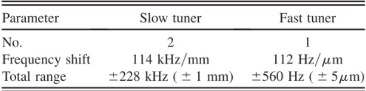
Applying the same tuning concept as used for the 325 MHz cavity described in Sec.I, the superconducting EUROTRANS CH cavities will contain seven static tuners, one fast and two slow bellow tuners. Figure13shows the simulated frequency range of the ten tuners for the first superconducting cavity. Based on this tuning range the working points for the static and the bellow tuners have been chosen with the aim to maximize the frequency gain while keeping the tuner height and the electrical peak fields to a minimum. For an adequate frequency adjustment
during fabrication, a maximum height of 25 mm for the static tuners is foreseen. TableIV contains the calculated frequency shift and the total range for the fast and the slow bellow tuners at a working point of 35 mm, which is sufficient for the cavity tuning during beam operation.
The electric field distribution on beam axis was opti- mized for every cavity by adjusting the gap-to-cell-length ratio (g=l). Figure14shows the simulated field distribution
FIG. 13. (Color) Simulated tuning range of ten hypothetic tuners operated in parallel and electrical peak fields appearing at the tuner surface.
FIG. 12. (Color) Layout of the first superconducting EUROTRANS CH cavity (simulation with MICROWAVE STUDIO
[18]).
FIG. 11. (Color) Layout of the 17 MeV EUROTRANS front end.
(bottom). The length of tube number three results from the integrated rebuncher section of the KONUS dynamics.
After passing the last room temperature CH cavity the first superconducting CH structure will increase the beam energy up to 7.5 MeV provided by an effective voltage of 2.5 MV. At a designQvalue of2108, a power of 18 W is
required without beam. Because of the optimized electric field, an effective voltage distribution on the beam axis has been achieved, which performs the required energy gain per gap (see Fig.15). A technical drawing of the first CH structure optimized for the EUROTRANS front end is shown by Fig. 16 while Table V summarizes the current main parameters for all superconducting CH cavities.
Based on the optimized superconducting as well as the room temperature CH cavities, beam dynamic simula- tions have been performed for the DTL part of the EUROTRANS injector (not including the RFQ part) [16].
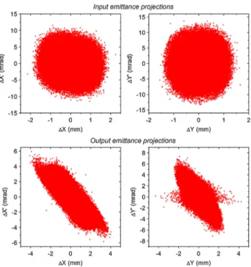
The transverse beam envelopes at 5 mA from the prelimi- nary design are shown in Fig.17, from which one can see that a large safety margin for the beam transport is avail- able throughout the injector linac. Figure 18 plots the transverse particle distributions at the two ends of the FIG. 15. (Color) Effective voltage on beam axis and related energy gain per gap for a synchronous particle of the first CH cavity.
FIG. 14. (Color) Simulation of the electric field distribution before and after the optimization (above), related gap and drift tube length for the flat field (bottom).
FIG. 16. First superconducting CH cavity optimized for the EUROTRANS front end.
DTL; the corresponding 100% rms emittance growths are about 15%.
IV. SUMMARY AND OUTLOOK
The superconducting CH structure is a multicell drift tube cavity for the low and medium energy range. It is an excellent candidate for the efficient acceleration in high power proton and ion applications because the large energy gain per cavity leads to high real estate gradients and to a significant reduction of required accelerator components.
A first prototype cavity has been built and tested suc- cessfully. At present, the construction of a 325 MHz CH cavity is in progress while another 217 MHz cavity is under development. Both cavities will be tested with beam at GSI.
The reference design of the 352 MHz, 600 MeV EUROTRANS proton driver linac using four supercon- ducting CH cavities for the 17 MeV front end was pro- posed by IAP, Frankfurt University. In this context the superconducting CH cavities were designed and optimized accordingly. Both room temperature CH cavities have al- ready been designed. Further simulations have to be done to improve the longitudinal beam dynamics in an iterative process. It is planned to build the first room temperature EUROTRANS CH cavity and test it with full rf power in the next years.
ACKNOWLEDGMENTS
This work has been supported by BMBF Contracts No. 06F134I and No. 06FY9089I, EU EUROTRANS Contract No. 516520-FI6W, EU-CARE-HIPPI No. RII3- CT-2003-506395, and by the Hessian Research Initiative LOEWE-HIC for FAIR. The authors would like to thank the company RI, Bergisch Gladbach, Germany, for the excellent work on technical drawings as well as in the fabrication of the prototype cavities. In addition, they would like to thank the technical staff of the IAP in Frankfurt, especially D. Ba¨nsch, I. Mu¨ller, and S. Reploeg.
FIG. 17. (Color) Transverse beam envelopes for the DTL part of the EUROTRANS injector.
TABLE V. Main parameters of the superconducting CH cav- ities for the EUROTRANS front end.
Parameter Unit CH-1 CH-2 CH-3 CH-4
(mean value) 0.117 0.138 0.159 0.178
Frequency MHz 352 352 352 352
Energy range MeV 5–7.4 7.4–10.4 10.4–13.9 13.9–17.4
Total length mm 696.6 862.9 1014.0 1124.3
Cavity diameter mm 286.1 300.8 316.3 332.5
Aperture diameter mm 25–30 30 40 40
Accelerating cells 13 14 14 14
Bellow tuner 3 3 3 3
Fixed tuner 7 7 7 7
G 56 58 60 63
Ra=Q0 1775 2143 1831 1999
RaRs k2 99 124 110 125
Q0 (BCS) 1:41091:5109 1:5109 1:6109 Q0 (goal) 2108 2108 2108 2108
Ea(definition) MV=m 3.9 3.9 3.9 3.6
Ep MV=m 26.5 28.1 28.5 27.4
Ep=Ea 6.8 7.2 7.3 7.6
Bp mT 39.8 35.9 45.2 36
Bp=Ea mT=ðMV=mÞ 10.2 9.2 11.6 10
Ua MV 2.5 3.2 3.7 3.8
Pc(for goalQ0) W 18 24 37 36
FIG. 18. (Color) Transverse emittance projections at the input and output of the EUROTRANS DTL part for 5 mA.
(2009).
[7] H. Podlechet al., Phys. Rev. ST Accel. Beams10, 080101 (2007).
[8] H. Podlech, Habilitationsschrift, University of Frankfurt, Germany, 2009.
[9] A. Bechtold et al., in Proceedings of the 2007 Superconducting RF Workshop, Bejing, China, p. 618.
[10] H. Podlech et al., in Proceedings of the 2009 Super-
[15] H. Podlech et al., in Proceedings of the 11th European Particle Accelerator Conference, Genoa, 2008(EPS-AG, Genoa, Italy, 2008), pp. 901–903.
[16] C. Zhang (unpublished).
[17] ANSYS Multiphysics, http://www.ansys.com.
[18] CST MICROWAVE STUDIO, http://www.cst.com.