USB in a Nutshell.
Making Sense of the USB Standard.
Starting out new with USB can be quite daunting. With the USB 2.0 specification at 650 pages one could easily be put off just by the sheer size of the standard. This is only the beginning of a long list of associated standards for USB. There are USB Class Standards such as the HID Class Specification which details the common operation of devices (keyboards, mice etc) falling under the HID (Human Interface Devices) Class - only another 97 pages. If you are designing a USB Host, then you have three Host Controller Interface Standards to choose from. None of these are detailed in the USB 2.0 Spec.
The good news is you don’t even need to bother reading the entire USB standard. Some chapters were churned out by marketing, others aimed at the lower link layer normally taken care off by your USB controller IC and a couple aimed at host and hub developers. Lets take a little journey through the various chapters of the USB 2.0 specification and briefly introduce the key points.
Chapter Name Description Pages
1 Introduction Includes the motivation and scope for USB. The most important piece of information in this chapter is to make reference to the Universal Serial Bus Device Class Specifications. No need reading this chapter.
2
2 Terms and
Abbreviations
This chapter is self-explanatory and a necessary evil to any standard. 8 3 Background Specifies the goals of USB which are Plug’n’Play and simplicity to the
end user (not developer). Introduces Low, Full and High Speed ranges with a feature list straight from marketing. No need reading this chapter either.
4
4 Architectural Overview
This is where you can start reading. This chapter provides a basic overview of a USB system including topology, data rates, data flow types, basic electrical specs etc.
10
5 USB Data Flow Model
This chapter starts to talk about how data flows on a Universal Serial Bus. It introduces terms such as endpoints and pipes then spends most of the chapter on each of the data flow types (Control, Interrupt, Isochronous and Bulk). While it’s important to know each transfer type and its properties it is a little heavy on for a first reader.
60
6 Mechanical This chapter details the USB’s two standard connectors. The important information here is that a type A connector is oriented facing
downstream and a type B connector upstream. Therefore it should be impossible to plug a cable into two upstream ports. All detachable cables must be full/high speed, while any low speed cable must be hardwired to the appliance. Other than a quick look at the connectors, you can skip this chapter unless you intend to manufacture USB connectors and/or cables. PCB designers can find standard footprints in this chapter.
33
7 Electrical This chapter looks at low level electrical signalling including line impedance, rise/fall times, driver/receiver specifications and bit level encoding, bit stuffing etc. The more important parts of this chapter are the device speed identification by using a resistor to bias either data line and bus powered devices vs self powered devices. Unless you are designing USB transceivers at a silicon level you can flip through this chapter. Good USB device datasheets will detail what value bus termination resistors you will need for bus impedance matching.
75
8 Protocol Layer Now we start to get into the protocol layers. This chapter describes the USB packets at a byte level including the sync, pid, address, endpoint, CRC fields. Once this has been grasped it moves on to the next protocol layer, USB packets. Most developers still don’t see these lower protocol layers as their USB device IC’s take care of this.
However an understanding of the status reporting and handshaking is worthwhile.
45
9 USB Device
Frame Work
This is the most frequently used chapter in the entire specification and
the only one I ever bothered printing and binding. This details the bus 36
10 USB Host Hardware and
Software
This chapter covers issues relating to the host. This includes frame and microframe generation, host controller requirements, software
mechanisms and the universal serial bus driver model. Unless you are designing Hosts, you can skip this chapter.
23
11 Hub Specification Details the workings of USB hubs including hub configuration, split transactions, standard descriptors for hub class etc. Unless you are designing Hubs, you can skip this chapter.
143
So now we can begin to read the parts of the standard relevant to our needs. If you develop drivers (Software) for USB peripherals then you may only need to read chapters,
• 4 - Architectural Overview
• 5 - USB Data Flow Model
• 9 - USB Device Frame Work, and
• 10 - USB Host Hardware and Software.
Peripheral hardware (Electronics) designers on the other hand may only need to read chapters,
• 4 - Architectural Overview
• 5 - USB Data Flow Model
• 6 - Mechanical, and
• 7 - Electrical.
USB in a NutShell for Peripheral Designers
Now lets face it, (1) most of us are here to develop USB peripherals and (2) it's common to read a standard and still have no idea how to implement a device. So in the next 7 chapters we focus on the relevant parts needed to develop a USB device. This allows you to grab a grasp of USB and its issues allowing you to further research the issues specific to your application.
The USB 1.1 standard was complex enough before High Speed was thrown into USB 2.0. In order to help understand the fundamental principals behind USB, we omit many areas specific to High Speed USB 2.0 devices. Once a grasp of USB 1.1 is obtained, these additional 2.0 details should be easy to pick up.
Introducing the Universal Serial Bus
USB version 1.1 supported two speeds, a full speed mode of 12Mbits/s and a low speed mode of 1.5Mbits/s.
The 1.5Mbits/s mode is slower and less susceptible to EMI, thus reducing the cost of ferrite beads and quality components. For example, crystals can be replaced by cheaper resonators. USB 2.0 which is still yet to see day light on mainstream desktop computers has upped the stakes to 480Mbits/s. The 480Mbits/s is known as High Speed mode and was a tack on to compete with the Firewire Serial Bus.
USB Speeds
• High Speed - 480Mbits/s
• Full Speed - 12Mbits/s
• Low Speed - 1.5Mbits/s
The Universal Serial Bus is host controlled. There can only be one host per bus. The specification in itself, does not support any form of multimaster arrangement. However the On-The-Go specification which is a tack on standard to USB 2.0 has introduced a Host Negotiation Protocol which allows two devices negotiate for the role of host. This is aimed at and limited to single point to point connections such as a mobile phone and personal organiser and not multiple hub, multiple device desktop configurations. The USB host is responsible for undertaking all transactions and scheduling bandwidth. Data can be sent by various transaction methods using a token-based protocol.
In my view the bus topology of USB is somewhat limiting. One of the original intentions of USB was to reduce the amount of cabling at the back of your PC. Apple people will say the idea came from the Apple Desktop Bus, where both the keyboard, mouse and some other peripherals could be connected together (daisy chained) using the one cable.
However USB uses a tiered star topology, simular to that of 10BaseT Ethernet. This imposes the use of a hub somewhere, which adds to greater expense, more boxes on your desktop and more cables. However it is not as bad as it may seem. Many devices have USB hubs integrated into them. For example, your keyboard may contain a hub which is connected to your computer. Your mouse and other devices such as your digital camera
can be plugged easily into the back of your keyboard. Monitors are just another peripheral on a long list which commonly have in-built hubs.
This tiered star topology, rather than simply daisy chaining devices together has some benefits. Firstly power to each device can be monitored and even switched off if an overcurrent condition occurs without disrupting other USB devices. Both high, full and low speed devices can be supported, with the hub filtering out high speed and full speed transactions so lower speed devices do not receive them.
Up to 127 devices can be connected to any one USB bus at any one given time. Need more devices? - Simply add another port/host. While earlier USB hosts had two ports, most manufacturers have seen this as limiting and are starting to introduce 4 and 5 port host cards with an internal port for hard disks etc. The early hosts had one USB controller and thus both ports shared the same available USB bandwidth. As bandwidth requirements grew, we are starting to see multi-port cards with two or more controllers allowing individual channels.
The USB host controllers have their own specifications. With USB 1.1, there were two Host Controller Interface Specifications, UHCI (Universal Host Controller Interface) developed by Intel which puts more of the burden on software (Microsoft) and allowing for cheaper hardware and the OHCI (Open Host Controller Interface)
developed by Compaq, Microsoft and National Semiconductor which places more of the burden on hardware(Intel) and makes for simpler software. Typical hardware / software engineer relationship. . . With the introduction of USB 2.0 a new Host Controller Interface Specification was needed to describe the register level details specific to USB 2.0. The EHCI (Enhanced Host Controller Interface) was born. Significant Contributors include Intel, Compaq, NEC, Lucent and Microsoft so it would hopefully seem they have pooled together to provide us one interface standard and thus only one new driver to implement in our operating systems. Its about time.
USB as its name would suggest is a serial bus. It uses 4 shielded wires of which two are power (+5v & GND).
The remaining two are twisted pair differential data signals. It uses a NRZI (Non Return to Zero Invert) encoding scheme to send data with a sync field to synchronise the host and receiver clocks.
USB supports plug’n’plug with dynamically loadable and unloadable drivers. The user simply plugs the device into the bus. The host will detect this addition, interrogate the newly inserted device and load the appropriate driver all in the time it takes the hourglass to blink on your screen provided a driver is installed for your device.
The end user needs not worry about terminations, terms such as IRQs and port addresses, or rebooting the computer. Once the user is finished, they can simply lug the cable out, the host will detect its absence and automatically unload the driver.
The loading of the appropriate driver is done using a PID/VID (Product ID/Vendor ID) combination. The VID is supplied by the USB Implementor's forum at a cost and this is seen as another sticking point for USB. The latest info on fees can be found on the USB Implementor’s Website
Other standards organisations provide an extra VID for non-commercial activities such as teaching, research or fiddling (The Hobbyist). The USB Implementors forum has yet to provide this service. In these cases you may wish to use one assigned to your development system's manufacturer. For example most chip manufacturers will have a VID/PID combination you can use for your chips which is known not to exist as a commercial device. Other chip manufacturers can even sell you a PID to use with their VID for your commercial device.
Another more notable feature of USB, is its transfer modes. USB supports Control, Interrupt, Bulk and Isochronous transfers. While we will look at the other transfer modes later, Isochronous allows a device to reserve a defined about of bandwidth with guaranteed latency. This is ideal in Audio or Video applications where congestion may cause loss of data or frames to drop. Each transfer mode provides the designer trade- offs in areas such as error detection and recovery, guaranteed latency and bandwidth.
Connectors
All devices have an upstream connection to the host and all hosts have a downstream connection to the device. Upstream and downstream connectors are not mechanically interchangeable, thus eliminating illegal loopback connections at hubs such as a downstream port connected to a downstream port. There are commonly two types of connectors, called type A and type B which are shown below.
Figure 1 : USB Connectors
Type A plugs always face upstream. Type A sockets will typically find themselves on hosts and hubs. For example type A sockets are common on computer main boards and hubs. Type B plugs are always connected downstream and consequently type B sockets are found on devices.
It is interesting to find type A to type A cables wired straight through and an array of USB gender changers in some computer stores. This is in contradiction of the USB specification. The only type A plug to type A plug devices are bridges which are used to connect two computers together. Other prohibited cables are USB extensions which has a plug on one end (either type A or type B) and a socket on the other. These cables violate the cable length requirements of USB.
USB 2.0 included errata which introduces mini-USB B connectors. The details on these connectors can be found in Mini-B Connector Engineering Change Notice. The reasoning behind the mini connectors came from the range of miniature electronic devices such as mobile phones and organisers. The current type B connector is too large to be easily integrated into these devices.
Just recently released has been the On-The-Go specification which adds peer-to-peer functionality to USB.
This introduces USB hosts into mobile phone and electronic organisers, and thus has included a specification for mini-A plugs, mini-A receptacles, and mini-AB receptacles. I guess we should be inundated with mini USB cables soon and a range of mini to standard converter cables.
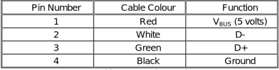
Pin Number Cable Colour Function
1 Red VBUS (5 volts)
2 White D-
3 Green D+
4 Black Ground
Table 1 : USB Pin Functions
Standard internal wire colours are used in USB cables, making it easier to identify wires from manufacturer to manufacturer. The standard specifies various electrical parameters for the cables. It is interesting to read the detail the original USB 1.0 spec included. You would understand it specifying electrical attributes, but
paragraph 6.3.1.2 suggested the recommended colour for overmolds on USB cables should be frost white - how boring! USB 1.1 and USB 2.0 was relaxed to recommend Black, Grey or Natural.
PCB designers will want to reference chapter 6 for standard foot prints and pinouts.
Electrical
Unless you are designing the silicon for a USB device/transceiver or USB host/hub, there is not all that much you need to know about the electrical specifications in chapter 7. We briefly address the essential points here.
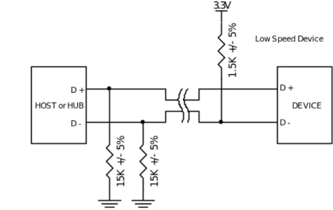
As we have discussed, USB uses a differential transmission pair for data. This is encoded using NRZI and is bit stuffed to ensure adequate transitions in the data stream. On low and full speed devices, a differential ‘1’ is transmitted by pulling D+ over 2.8V with a 15K ohm resistor pulled to ground and D- under 0.3V with a 1.5K ohm resistor pulled to 3.6V. A differential ‘0’ on the other hand is a D- greater than 2.8V and a D+ less than 0.3V with the same appropriate pull down/up resistors.
The receiver defines a differential ‘1’ as D+ 200mV greater than D- and a differential ‘0’ as D+ 200mV less than D-. The polarity of the signal is inverted depending on the speed of the bus. Therefore the terms ‘J’ and ‘K’
states are used in signifying the logic levels. In low speed a ‘J’ state is a differential 0. In high speed a ‘J’ state is a differential 1.
USB transceivers will have both differential and single ended outputs. Certain bus states are indicated by single ended signals on D+, D- or both. For example a single ended zero or SE0 can be used to signify a
1 2 3 4
Receptacle Type A Receptical Type B 1 2 3 4
device reset if held for more than 10mS. A SE0 is generated by holding both D- and D+ low (< 0.3V). Single ended and differential outputs are important to note if you are using a transceiver and FPGA as your USB device. You cannot get away with sampling just the differential output.
The low speed/full speed bus has a characteristic impedance of 90 ohms +/- 15%. It is therefore important to observe the datasheet when selecting impedance matching series resistors for D+ and D-. Any good datasheet should specify these values and tolerances.
High Speed (480Mbits/s) mode uses a 17.78mA constant current for signalling to reduce noise.
Speed Identification
A USB device must indicate its speed by pulling either the D+ or D- line high to 3.3 volts. A full speed device, pictured below will use a pull up resistor attached to D+ to specify itself as a full speed device. These pull up resistors at the device end will also be used by the host or hub to detect the presence of a device connected to its port. Without a pull up resistor, USB assumes there is nothing connected to the bus. Some devices have this resistor built into its silicon, which can be turned on and off under firmware control, others require an external resistor.
For example Philips Semiconductor has a SoftConnectTM technology. When first connected to the bus, this allows the microcontroller to initialise the USB function device before it enables the pull up speed identification resistor, indicating a device is attached to the bus. If the pull up resistor was connected to Vbus, then this would indicate a device has been connected to the bus as soon as the plug is inserted. The host may then attempt to reset the device and ask for a descriptor when the microprocessor hasn’t even started to initialise the usb function device.
Other vendors such as Cypress Semiconductor also use a programmable resistor for Re-NumerationTM purposes in their EzUSB devices where the one device can be enumerated for one function such as In field programming then be disconnected from the bus under firmware control, and enumerate as another different device, all without the user lifting an eyelid. Many of the EzUSB devices do not have any Flash or OTP ROM to store code. They are bootstraped at connection
Figure 2 : Full Speed Device with pull up resistor connected to D- Figure 3 : Low Speed Device with pull up resistor connected to D+
You will notice we have not included speed identification for High Speed mode. High speed devices will start by connecting as a full speed device (1.5k to 3.3V). Once it has been attached, it will do a high speed chirp during reset and establish a high speed connection if the hub supports it. If the device operates in high speed mode, then the pull up resistor is removed to balance the line.
A USB 2.0 compliant device is not required to support high-speed mode. This allows cheaper devices to be produced if the speed isn’t critical. This is also the case for a low speed USB 1.1 devices which is not required to support full speed.
However a high speed device must not support low speed mode. It should only support full speed mode needed to connect first, then high speed mode if successfully negotiated later. An USB 2.0 compliant
15K +/- 5% 15K +/- 5%
D +
D -
HOST or HUB DEVICE
D +
D -
1.5K +/- 5%
3.3V
Full Speed Device
15K +/- 5% 15K +/- 5%
D +
D -
HOST or HUB DEVICE
D +
D -
1.5K +/- 5%
3.3V
Low Speed Device
Power (VBUS)
One of the benefits of USB is bus-powered devices - devices which obtain its power from the bus and requires no external plug packs or additional cables. However many leap at this option without first considering all the necessary criteria.
A USB device specifies its power consumption expressed in 2mA units in the configuration descriptor which we will examine in detail later. A device cannot increase its power consumption, greater than what it specifies during enumeration, even if it looses external power. There are three classes of USB functions,
• Low-power bus powered functions
• High-power bus powered functions
• Self-powered functions
Low power bus powered functions draw all its power from the VBUS and cannot draw any more than one unit load. The USB specification defines a unit load as 100mA. Low power bus powered functions must also be designed to work down to a VBUS voltage of 4.40V and up to a maximum voltage of 5.25V measured at the upsteam plug of the device. For many 3.3V devices, LDO regulators are mandatory.
High power bus powered functions will draw all its power from the bus and cannot draw more than one unit load until it has been configured, after which it can then drain 5 unit loads (500mA Max) provided it asked for this in its descriptor. High power bus functions must be able to be detected and enumerated at a minimum 4.40V. When operating at a full unit load, a minimum VBUS of 4.75 V is specified with a maximum of 5.25V.
Once again, these measurements are taken at the upstream plug.
Self power functions may draw up to 1 unit load from the bus and derive the rest of it’s power from an external source. Should this external source fail, it must have provisions in place to draw no more than 1 unit load from the bus. Self powered functions are easier to design to specification as there is not so much of an issue with power consumption. The 1 unit bus powered load allows the detection and enumeration of devices without mains/secondary power applied.
No USB device, whether bus powered or self powered can drive the VBUS on its upstream facing port. If VBUS is lost, the device has a lengthy 10 seconds to remove power from the D+/D- pull-up resistors used for speed identification.
Other VBUS considerations are the Inrush current which must be limited. This is outlined in the USB
specification paragraph 7.2.4.1 and is commonly overlooked. Inrush current is contributed to the amount of capacitance on your device between VBUS and ground. The spec therefore specifies that the maximum
decoupling capacitance you can have on your device is 10uF. When you disconnect the device after current is flowing through the inductive USB cable, a large flyback voltage can occur on the open end of the cable. To prevent this, a 1uF minimum VBUS decoupling capacitance is specified.
For the typical bus powered device, it can not drain any more than 500mA which is not unreasonable. So what is the complication you ask? Prehaps Suspend Mode?
Suspend Current
Suspend mode is mandatory on all devices. During suspend, additional constrains come into force. The maximum suspend current is proportional to the unit load. For a 1 unit load device (default) the maximum suspend current is 500uA. This includes current from the pull up resistors on the bus. At the hub, both D- and D+ have pull down resistors of 15K ohms. For the purposes of power consumption, the pull down resistor at the device is in series with the 1.5K ohms pull up, making a total load of 16.5K ohms on a VTERM of typically 3.3v.
Therefore this resistor sinks 200uA before we even start.
Another consideration for many devices is the 3.3V regulator. Many of the USB devices run on 3.3V. The PDIUSBD11 is one such example. Linear regulators are typically quite inefficient with average quiescent currents in the order of 600uA, therefore more efficient and thus expensive regulators are called for. In the majority of cases, you must also slow down or stop clocks on microcontrollers to fall within the 500uA limit.
Many developers ask in the USB Implementor's Forum, what are the complications of exceeding this limit? It is understood, that most hosts and hubs don’t have the ability to detect such an overload of this magnitude and thus if you drain maybe 5mA or even 10mA you should still be fine, bearing in mind that at the end of the day, your device violates the USB specification. However in normal operation, if you try to exceed the 100mA or your designated permissible load, then expect the hub or host to detect this and disconnect your device, in the interest of the integrity of the bus.
Of course these design issues can be avoided if you choose to design a self powered device. Suspend currents may not be a great concern for desktop computers but with the introduction of the On-The-Go Specification we will start seeing USB hosts built into mobile phones and mobile organisers. The power consumption pulled from these devices will adversely effect the operating life of the battery.
Entering Suspend Mode
A USB device will enter suspend when there is no activity on the bus for greater than 3.0ms. It then has a further 7ms to shutdown the device and draw no more than the designated suspend current and thus must be only drawing the rated suspend current from the bus 10mS after bus activity stopped. In order to maintain connected to a suspended hub or host, the device must still provide power to its pull up speed selection resistors during suspend.
USB has a start of frame packet or keep alive sent periodically on the bus. This prevents an idle bus from entering suspend mode in the absence of data.
• A high speed bus will have micro-frames sent every 125.0 µs ±62.5 ns.
• A full speed bus will have a frame sent down each 1.000 ms ±500 ns.
• A low speed bus will have a keep alive which is a EOP (End of Packet) every 1ms only in the absence of any low speed data.
The term "Global Suspend" is used when the entire USB bus enters suspend mode collectively. However selected devices can be suspended by sending a command to the hub that the device is connected too. This is referred to as a "Selective Suspend."
The device will resume operation when it receives any non idle signalling. If a device has remote wakeup enabled then it may signal to the host to resume from suspend.
Data Signalling Rate
Another area which is often overlooked is the tolerance of the USB clocks. This is specified in the USB specification, section 7.1.11.
• High speed data is clocked at 480.00Mb/s with a data signalling tolerance of ± 500ppm.
• Full speed data is clocked at 12.000Mb/s with a data signalling tolerance of ±0.25% or 2,500ppm.
• Low speed data is clocked at 1.50Mb/s with a data signalling tolerance of ±1.5% or 15,000ppm.
This allows resonators to be used for low cost low speed devices, but rules them out for full or high speed devices.
USB Protocols
Unlike RS-232 or similar serial interfaces where the format of data being sent is not defined, USB is made up of several layers of protocols. While this sounds complicated, don’t give up now. Once you understand what is going on, you really only have to worry about the higher level layers. In fact most USB controller I.C.s will take care of the lower layer, thus making it almost invisible to the end designer.
Each USB transaction consists of a
• Token Packet (Header defining what it expects to follow), an
• Optional Data Packet, (Containing the payload) and a
• Status Packet (Used to acknowledge transactions and to provide a means of error correction) As we have already discussed, USB is a host centric bus. The host initiates all transactions. The first packet, also called a token is generated by the host to describe what is to follow and whether the data transaction will be a read or write and what the device’s address and designated endpoint is. The next packet is generally a data packet carrying the payload and is followed by an handshaking packet, reporting if the data or token was received successfully, or if the endpoint is stalled or not available to accept data.
Common USB Packet Fields
Data on the USBus is transmitted LSBit first. USB packets consist of the following fields,
Sync
All packets must start with a sync field. The sync field is 8 bits long, which is used to synchronise the clock of the receiver with the transmitter. The last two bits indicate where the PID fields starts.
PID
PID stands for Packet ID. This field is used to identify the type of packet that is being sent. The following table shows the possible values.
Group PID Value Packet Identifier
0001 OUT Token
1001 IN Token
0101 SOF Token
Token
1101 SETUP Token
0011 DATA0
1011 DATA1
0111 DATA2
Data
1111 MDATA
0010 ACK Handshake
1010 NAK Handshake
1110 STALL Handshake
Handshake
0110 NYET (No Response Yet)
1100 PREamble
1100 ERR
1000 Split
Special
0100 Ping
There is 4 bits to the PID, however to insure it is received correctly, the 4 bits are complemented and repeated, making an 8 bit PID in total. The resulting format is shown below.
PID0 PID1 PID2 PID3 nPID0 nPID1 nPID2 nPID3 ADDR
The address field specifies which device the packet is designated for. Being 7 bits in length allows for 127 devices to be supported. Address 0 is not valid, as any device which is not yet assigned an address must respond to packets sent to address zero.
ENDP
The endpoint field is made up of 4 bits, allowing 16 possible endpoints. Low speed devices, however can only have 2 endpoint additional addresses on top of the default pipe. (4 Endpoints Max)
CRC
Cyclic Redundancy Checks are performed on the data within the packet payload. All token packets have a 5 bit CRC while data packets have a 16 bit CRC.
EOP
End of packet. Signalled by a Single Ended Zero (SE0) for approximately 2 bit times followed by a J for 1 bit time.
USB Packet Types
USB has four different packet types. Token packets indicate the type of transaction to follow, data packets contain the payload, handshake packets are used for acknowledging data or reporting errors and start of frame packets indicate the start of a new frame.
Token Packets
There are three types of token packets,
In – Informs the USB device that the host wishes to read information.
Out - Informs the USB device that the host wishes to send information.
Setup – Used to begin control transfers.
Token Packets must conform to the following format,
Sync PID ADDR ENDP CRC5 EOP
Data Packets
There are two types of data packets each capable of transmitting 0 to 1023 bytes of data.
Data0 Data1
Data packets have the following format
Sync PID Data CRC16 EOP
Handshake Packets
There are three type of handshake packets which consist simply of the PID ACK – Acknowledgment that the packet has been successfully received.
NAK – Reports that the device cannot send nor received data temporary. Also used during interrupt transaction to inform the host there is no data to send.
STALL – The device finds its in a state that it requires intervention from the host.
Handshake Packets have the following format,
Sync PID EOP
Start of Frame Packets
The SOF packet consisting of an 11-bit frame number is sent by the host every 1mS ± 500nS.
Sync PID Frame Number CRC5 EOP
USB Functions
When we think of a USB device, we think of a USB peripheral, but a USB device could mean a USB
transceiver device used at the host or peripheral, a USB Hub or Host Controller IC device, or a USB peripheral device. The standard therefore makes references to USB functions which can be seen as USB devices which provide a capability or function such as a Printer, Zip Drive, Scanner, Modem or other peripheral.
So by now we should know the sort of things which make up a USB packet. No? You're forgotten how many bits make up a PID field already? Well don't be too alarmed. Fortunately most USB functions handle the low level USB protocols up to the transaction layer (which we will cover next chapter) in silicon. The reason why we cover this information is most USB function controllers will report errors such as PID Encoding Error. Without briefly covering this, one could ask what is a PID Encoding Error? If you suggested that the last four bits of the PID didn't match the inverse of the first four bits then you would be right.
Most functions will have a series of buffers, typically 8 bytes long. Each buffer will belong to an endpoint - EP0 IN, EP0 OUT etc. Say for example, the host sends a device descriptor request. The function hardware will read the setup packet and determine from the address field whether the packet is for itself, and if so will copy the payload of the following data packet to the appropriate endpoint buffer dictated by the value in the endpoint field of the setup token. It will then send a handshake packet to acknowledge the reception of the byte and generate an internal interrupt within the semiconductor/micro-controller for the appropriate endpoint signifying it has received a packet. This is typically all done in hardware.
The software now gets an interrupt, and should read the contents of the endpoint buffer and parse the device descriptor request.
Endpoints
Endpoints can be described as sources or sinks of data. As the bus is host centric, endpoints occur at the end of the communications channel at the USB function. At the software layer, your device driver may send a packet to your devices EP1 for example. As the data is flowing out from the host, it will end up in the EP1 OUT buffer. Your firmware will then at its leisure read this data. If it wants to return data, the function cannot simply write to the bus as the bus is controlled by the host. Therefore it writes data to EP1 IN which sits in the buffer until such time when the host sends a IN packet to that endpoint requesting the data. Endpoints can also be seen as the interface between the hardware of the function device and the firmware running on the function device.
All devices must support endpoint zero. This is the endpoint which receives all of the devices control and status requests during enumeration and throughout the duration while the device is operational on the bus.
Addr = 2
EP0 In
Addr = 3 Host
Bus
USB Device USB Device
EP0 Out EP1 In EP1 Out
EP0 In EP0 Out
EP1 In EP1 Out
EP.. In EP.. Out
My Function
My Function [Addr][Endpoint][Direction]
Pipes
While the device sends and receives data on a series of endpoints, the client software transfers data through pipes. A pipe is a logical connection between the host and endpoint(s). Pipes will also have a set of parameters associated with them such as how much bandwidth is allocated to it, what transfer type (Control, Bulk, Iso or Interrupt) it uses, a direction of data flow and maximum packet/buffer sizes. For example the default pipe is a bi-directional pipe made up of endpoint zero in and endpoint zero out with a control transfer type.
USB defines two types of pipes
• Stream Pipes have no defined USB format, that is you can send any type of data down a stream pipe and can retrieve the data out the other end. Data flows sequentially and has a pre-defined direction, either in or out. Stream pipes will support bulk, isochronous and interrupt transfer types. Stream pipes can either be controlled by the host or device.
• Message Pipes have a defined USB format. They are host controlled, which are initiated by a request sent from the host. Data is then transferred in the desired direction, dictated by the request. Therefore message pipes allow data to flow in both directions but will only support control transfers.
Endpoint Types
The Universal Serial Bus specification defines four transfer/endpoint types,
• Control Transfers
• Interrupt Transfers
• Isochronous Transfers
• Bulk Transfers
Control Transfers
Control transfers are typically used for command and status operations. They are essential to set up a USB device with all enumeration functions being performed using control transfers. They are typically bursty, random packets which are initiated by the host and use best effort delivery. The packet length of control transfers in low speed devices must be 8 bytes, high speed devices allow a packet size of 8, 16, 32 or 64 bytes and full speed devices must have a packet size of 64 bytes.
A control transfer can have up to three stages.
• The Setup Stage is where the request is sent. This consists of three packets. The setup token is sent first which contains the address and endpoint number. The data packet is sent next and always has a PID type of data0 and includes a setup packet which details the type of request. We detail the setup packet later. The last packet is a handshake used for acknowledging successful receipt or to indicate an error. If the function successfully receives the setup data (CRC and PID etc OK) it responds with ACK, otherwise it ignores the data and doesn’t send a handshake packet. Functions cannot issue a STALL or NAK packet in response to a setup packet.
• The optional Data Stage consists of one or multiple IN or OUT transfers. The setup request indicates the amount of data to be transmitted in this stage. If it exceeds the maximum packet size, data will be sent in multiple transfers each being the maximum packet length except for the last packet.
The data stage has two different scenarios depending upon the direction of data transfer.
• IN: When the host is ready to receive control data it issues an IN Token. If the function receives the IN token with an error e.g. the PID doesn't match the inverted PID bits, then it ignores the packet. If the token was received correctly, the device can either reply with a DATA packet containing the control data to be sent, a stall packet indicating the endpoint has had a error or a NAK packet indicating to the host that the endpoint is working, but temporary has no data to send.
• OUT: When the host needs to send the device a control data packet, it issues an OUT token followed by a data packet containing the control data as the payload. If any part of the OUT token or data packet is corrupt then the function ignores the packet. If the function's endpoint buffer was empty and it has clocked the data into the endpoint buffer it issues an ACK informing the host it
Host Function Key
Host Function Key
IN DATA x
NAK STALL
ACK
OUT DATA x ACK
NAK
STALL
Token Packet Data Packet Handshake Packet
Data Error
In Token Error
Data Error
SETUP DATA 0 ACK
Token Packet Data Packet Handshake Packet
Setup Token Error Data Error
has successfully received the data. If the endpoint buffer is not empty due to processing of the previous packet, then the function returns a NAK. However if the endpoint has had a error and its halt bit has been set, it returns a STALL.
• Status Stage reports the status of the overall request and this once again varies due to direction of transfer. Status reporting is always performed by the function.
• IN: If the host sent IN token(s) during the data stage to receive data, then the host must
acknowledge the successful recept of this data. This is done by the host sending an OUT token followed by a zero length data packet. The function can now report its status in the handshaking stage. An ACK indicates the function has completed the command is now ready to accept another command. If an error occurred during the processing of this command, then the function will issue a STALL. However if the function is still processing, it returns a NAK indicating to the host to repeat the status stage later.
• OUT: If the host sent OUT token(s) during the data stage to transmit data, the function will acknowledge the successful recept of data by sending a zero length packet in response to an IN token. However if an error occurred, it should issue a STALL or if it is still busy processing data, it should issue a NAK asking the host to retry the status phase later.
IN DATA0
Zero Length
NAK STALL
ACK
Still Processing Normal Completion
Error
OUT DATA0
Zero Length ACK
STALL
NAK Normal
Completion
Error Still Processing
Control Transfers : The bigger picture
Now how does all this fit together? Let's say for example, the Host wants to request a device descriptor during enumeration. The packets which are sent are as follows.
The host will send the Setup token telling the function that the following packet is a Setup packet. The Address field will hold the address of the device the host is requesting the descriptor from. The endpoint number should be zero, specifying the default pipe. The host will then send a DATA0 packet. This will have an 8 byte payload which is the Device Descriptor Request as outlined in Chapter 9 of the USB
Specification. The USB function then acknowledges the setup packet has been read correctly with no errors. If the packet was received corrupt, the device just ignores this packet. The host will then resend the packet after a short delay.
1. Setup Token Sync PID ADDR ENDP CRC5 EOP Address & Endpoint Number 2. Data0 Packet Sync PID Data0 CRC16 EOP Device Descriptor Request
3. Ack Handshake Sync PID EOP Device Ack. Setup Packet
The above three packets represent the first USB transaction. The USB device will now decode the 8 bytes received, and determine it was a device descriptor request. The device will then attempt to send the Device Descriptor, which will be the next USB transaction.
1. In Token Sync PID ADDR ENDP CRC5 EOP Address & Endpoint Number 2. Data1 Packet Sync PID Data1 CRC16 EOP First 8 bytes of Device Descriptor
3. Ack Handshake Sync PID EOP Host Acknowledges Packet
1. In Token Sync PID ADDR ENDP CRC5 EOP Address & Endpoint Number 2. Data0 Packet Sync PID Data0 CRC16 EOP Second 8 bytes of Device Desc
3. Ack Handshake Sync PID EOP Host Acknowledges Packet
1. In Token Sync PID ADDR ENDP CRC5 EOP Address & Endpoint Number 2. Data1/0 Packet Sync PID Data0/1 CRC16 EOP Last 8 bytes of Device Descriptor
3. Ack Handshake Sync PID EOP Host Acknowledges Packet
In this case, we assume that the maximum payload size is 8 bytes. The host sends the IN token, telling the device it can now send data for this endpoint. As the maximum packet size is 8 bytes, we must split up the 12 byte device descriptor into chunks to send. Each chunk must be 8 bytes except for the last transaction.
The host acknowledges every data packet we send it.
Once the device descriptor is sent, a status transaction follows. If the transactions were successful, the host will send a zero length packet indicating the overall transaction was successful. The function then replies to this zero length packet indicating its status.
1. Out Token Sync PID ADDR ENDP CRC5 EOP Address & Endpoint Number 2. Data1 Packet Sync PID Data1 CRC16 EOP Zero Length Packet
3. Ack Handshake Sync PID EOP Function Ack. Entire Transactions
Interrupt Transfers
Any one who has had experience of interrupt requests on microcontrollers will know that interrupts are device generated. However under USB if a device requires the attention of the host, it must wait until the host polls it before it can report that it needs urgent attention!
Interrupt Transfers
• Guaranteed Latency
• Stream Pipe - Unidirectional
• Error detection and next period retry.
Interrupt transfers are typically non-periodic, small device "initiated" communication requiring bounded latency. An Interrupt request is queued by the device until the host polls the USB device asking for data.
• The maximum data payload size for low-speed devices is 8 bytes.
• Maximum data payload size for full-speed devices is 64 bytes.
• Maximum data payload size for high-speed devices is 1024 bytes.
The above diagram shows the format of an Interrupt IN and Interrupt OUT transaction.
• IN: The host will periodically poll the interrupt endpoint. This rate of polling is specified in the endpoint descriptor which is covered later. Each poll will involve the host sending an IN Token. If the IN token is corrupt, the function ignores the packet and continues monitoring the bus for new tokens.
If an interrupt has been queued by the device, the function will send a data packet containing data relevant to the interrupt when it receives the IN Token. Upon successful recept at the host, the host will return an ACK. However if the data is corrupted, the host will return no status. If on the other hand a interrupt condition was not present when the host polled the interrupt endpoint with an IN token, then the function signals this state by sending a NAK. If an error has occurred on this endpoint, a STALL is sent in reply to the IN token instead.
• OUT: When the host wants to send the device interrupt data, it issues an OUT token followed by a data packet containing the interrupt data. If any part of the OUT token or data packet is corrupt then the function ignores the packet. If the function's endpoint buffer was empty and it has clocked the data into the endpoint buffer it issues an ACK informing the host it has successfully received the data. If the endpoint buffer is not empty due to processing of a previous packet, then the function returns an NAK. However if an error occurred with the endpoint consequently and its halt bit has been set, it returns a STALL.
IN DATA x
NAK STALL
ACK
OUT DATA x ACK
NAK
STALL
Token Packet Data Packet Handshake Packet Data Error
In Token Error No Interrupt Pending
Success
Halt
Error Success
Failure
Halt
Host Function Key
Isochronous Transfers
Isochronous transfers occur continuously and periodically. They typically contain time sensitive information, such as an audio or video stream. If there were a delay or retry of data in an audio stream, then you would expect some erratic audio containing glitches. The beat may no longer be in sync. However if a packet or frame was dropped every now and again, it is less likely to be noticed by the listener.
Isochronous Transfers provide
• Guaranteed access to USB bandwidth.
• Bounded latency.
• Stream Pipe - Unidirectional
• Error detection via CRC, but no retry or guarantee of delivery.
• Full & high speed modes only.
• No data toggling.
The maximum size data payload is specified in the endpoint descriptor of an Isochronous Endpoint. This can be up to a maximum of 1023 bytes for a full speed device and 1024 bytes for a high speed device. As the maximum data payload size is going to effect the bandwidth requirements of the bus, it is wise to specify a conservative payload size. If you are using a large payload, it may also be to your advantage to specify a series of alternative interfaces with varying isochronous payload sizes. If during enumeration, the host cannot enable your preferred isochronous endpoint due to bandwidth restrictions, it has something to fall back on rather than just failing completely. Data being sent on an isochronous endpoint can be less than the pre- negotiated size and may vary in length from transaction to transaction.
The above diagram shows the format of an Isochronous IN and OUT transaction. Isochronous transactions do not have a handshaking stage and cannot report errors or STALL/HALT conditions.
Host Function Key
IN
OUT DATA x
DATA x
Token Packet Data Packet
Bulk Transfers
Bulk transfers can be used for large bursty data. Such examples could include a print-job sent to a printer or an image generated from a scanner. Bulk transfers provide error correction in the form of a CRC16 field on the data payload and error detection/re-transmission mechanisms ensuring data is transmitted and received without error.
Bulk transfers will use spare un-allocated bandwidth on the bus after all other transactions have been
allocated. If the bus is busy with isochronous and/or interrupt then bulk data may slowly trickle over the bus. As a result Bulk transfers should only be used for time insensitive communication as there is no guarantee of latency.
Bulk Transfers
• Used to transfer large bursty data.
• Error detection via CRC, with guarantee of delivery.
• No guarantee of bandwidth or minimum latency.
• Stream Pipe - Unidirectional
• Full & high speed modes only.
Bulk transfers are only supported by full and high speed devices. For full speed endpoints, the maximum bulk packet size is either 8, 16, 32 or 64 bytes long. For high speed endpoints, the maximum packet size can be up to 512 bytes long. If the data payload falls short of the maximum packet size, it doesn't need to be padded with zeros. A bulk transfer is considered complete when it has transferred the exact amount of data requested, transferred a packet less than the maximum endpoint size of transferred a zero-length packet.
The above diagram shows the format of a bulk IN and OUT transaction.
• IN: When the host is ready to receive bulk data it issues an IN Token. If the function receives the IN token with an error, it ignores the packet. If the token was received correctly, the function can either reply with a DATA packet containing the bulk data to be sent, or a stall packet indicating the endpoint has had a error or a NAK packet indicating to the host that the endpoint is working, but temporary has no data to send.
• OUT: When the host wants to send the function a bulk data packet, it issues an OUT token followed by a data packet containing the bulk data. If any part of the OUT token or data packet is corrupt then the function ignores the packet. If the function's endpoint buffer was empty and it has clocked the data into the endpoint buffer it issues an ACK informing the host it has successfully received the data. If the endpoint buffer is not empty due to processing a previous packet, then the
IN DATA x
NAK STALL
ACK
OUT DATA x ACK
NAK
STALL
Token Phase Data Phase Handshake Phase
Bandwidth Management
The host is responsible in managing the bandwidth of the bus. This is done at enumeration when configuring Isochronous and Interrupt Endpoints and throughout the operation of the bus. The specification places limits on the bus, allowing no more than 90% of any frame to be allocated for periodic transfers (Interrupt and
Isochronous) on a full speed bus. On high speed buses this limitation gets reduced to no more than 80% of a microframe can be allocated for periodic transfers.
So you can quite quickly see that if you have a highly saturated bus with periodic transfers, the remaining 10%
is left for control transfers and once those have been allocated, bulk transfers will get its slice of what is left.
USB Descriptors
All USB devices have a hierarchy of descriptors which describe to the host information such as what the device is, who makes it, what version of USB it supports, how many ways it can be configured, the number of
endpoints and their types etc
The more common USB descriptors are
• Device Descriptors
• Configuration Descriptors
• Interface Descriptors
• Endpoint Descriptors
• String Descriptors
USB devices can only have one device descriptor. The device descriptor includes information such as what USB revision the device complies to, the Product and Vendor IDs used to load the appropriate drivers and the number of possible configurations the device can have. The number of configurations indicate how many configuration descriptors branches are to follow.
The configuration descriptor specifies values such as the amount of power this particular configuration uses, if the device is self or bus powered and the number of interfaces it has. When a device is enumerated, the host reads the device descriptors and can make a decision of which configuration to enable. It can only enable one configuration at a time.
For example, It is possible to have a high power bus powered configuration and a self powered configuration. If the device is plugged into a host with a mains power supply, the device driver may choose to enable the high power bus powered configuration enabling the device to be powered without a connection to the mains, yet if it is connected to a laptop or personal organiser it could enable the 2nd configuration (self powered) requiring the user to plug your device into the power point.
The configuration settings are not limited to power differences. Each configuration could be powered in the same way and draw the same current, yet have different interface or endpoint combinations. However it should be noted that changing the configuration requires all activity on each endpoint to stop. While USB offers this flexibility, very few devices have more than 1 configuration.
DeviceDescriptor
Configuration Descriptor
Interface Descriptor
Endpoint Descriptor
bNumConfigurations
Endpoint Descriptor
Interface Descriptor
Endpoint Descriptor
Endpoint Descriptor bNumInterfaces
bNumEndpoints bNumEndpoints
Configuration Descriptor
Interface Descriptor
Endpoint Descriptor
Endpoint Descriptor
Interface Descriptor
Endpoint Descriptor
Endpoint Descriptor bNumInterfaces
bNumEndpoints bNumEndpoints
The interface descriptor could be seen as a header or grouping of the endpoints into a functional group performing a single feature of the device. For example you could have a multi-function fax/scanner/printer device. Interface descriptor one could describe the endpoints of the fax function, Interface descriptor two the scanner function and Interface descriptor three the printer function. Unlike the configuration descriptor, there is no limitation as to having only one interface enabled at a time. A device could have 1 or many interface descriptors enabled at once.
Interface descriptors have a bInterfaceNumber field specifying the Interface number and a bAlternateSetting which allows an interface to change settings on the fly. For example we could have a device with two
interfaces, interface one and interface two. Interface one has bInterfaceNumber set to zero indicating it is the first interface descriptor and a bAlternativeSetting of zero.
Interface two would have a bInterfaceNumber set to one indicating it is the second interface and a bAlternativeSetting of zero (default). We could then throw in another descriptor, also with a
bInterfaceNumber set to one indicating it is the second interface, but this time setting the bAlternativeSetting to one, indicating this interface descriptor can be an alternative setting to that of the other interface descriptor two.
When this configuration is enabled, the first two interface descriptors with bAlternativeSettings equal to zero is used. However during operation the host can send a SetInterface request directed to that of Interface one with an alternative setting of one to enable the other interface descriptor.
This gives an advantage over having two configurations, in that we can be transmitting data over interface zero while we change the endpoint settings associated with interface one without effecting interface zero.
Each endpoint descriptor is used to specify the type of transfer, direction, polling interval and maximum packet size for each endpoint. Endpoint zero, the default control endpoint is always assumed to be a control endpoint and as such never has a descriptor.
Composition of USB Descriptors
All descriptors are made up of a common format. The first byte specifies the length of the descriptor, while the second byte indicates the descriptor type. If the length of a descriptor is smaller than what the specification defines, then the host shall ignore it. However if the size is greater than expected the host will ignore the extra bytes and start looking for the next descriptor at the end of actual length returned.
Offset Field Size Value Description
0 bLength 1 Number Size of the Descriptor in Bytes
1 bDescriptorType 1 Constant Description Type
2 bcdUSB 2 BCD USB Start of parameters for descriptor
Device Descriptors
The device descriptor of a USB device represents the entire device. As a result a USB device can only have one device descriptor. It specifies some basic, yet important information about the device such as the supported USB version, maximum packet size, vendor and product IDs and the number of possible configurations the device can have. The format of the device descriptor is shown below.
Offset Field Size Value Description
0 bLength 1 Number Size of the Descriptor in Bytes (18 bytes) 1 bDescriptorType 1 Constant Device Descriptor (0x01)
2 bcdUSB 2 BCD USB Specification Number which device complies too.
4 bDeviceClass 1 Class Class Code
If equal to Zero, each interface specifies it’s own class code
if equal to 0xFF, the class code is vendor specified.
Otherwise field is valid Class Code.
5 bDeviceSubClass 1 SubClass Subclass Code (Assigned by USB Org) 6 bDeviceProtocol 1 Protocol Protocol Code (Assigned by USB Org)
7 bMaxPacketSize 1 Number Maximum Packet Size for Zero Endpoint. Valid Sizes are 8, 16, 32, 64
8 idVendor 2 ID Vendor ID (Assigned by USB Org)
10 idProduct 2 ID Product ID (Assigned by Manufacturer)
12 bcdDevice 2 BCD Device Release Number
14 iManufacturer 1 Index Index of Manufacturer String Descriptor 15 iProduct 1 Index Index of Product String Descriptor 16 iSerialNumber 1 Index Index of Serial Number String Descriptor 17 bNumConfigurations 1 Integer Number of Possible Configurations
• The bcdUSB field reports the highest version of USB the device supports. The value is in binary coded decimal with a format of 0xJJMN where JJ is the major version number, M is the minor version number and N is the sub minor version number. e.g. USB 2.0 is reported as 0x0200, USB 1.1 as 0x0110 and USB 1.0 as 0x0100.
• The bDeviceClass, bDeviceSubClass and bDeviceProtocol are used by the operating system to find a class driver for your device. Typically only the bDeviceClass is set at the device level. Most class specifications choose to identify itself at the interface level and as a result set the
bDeviceClass as 0x00. This allows for the one device to support multiple classes.
• The bMaxPacketSize field reports the maximum packet size for endpoint zero. All devices must support endpoint zero.
• The idVendor and idProduct are used by the operating system to find a driver for your device.
The Vendor ID is assigned by the USB-IF.
• The bcdDevice has the same format than the bcdUSB and is used to provide a device version number. This value is assigned by the developer.
• Three string descriptors exist to provide details of the manufacturer, product and serial number.
There is no requirement to have string descriptors. If no string descriptor is present, a index of zero should be used.
• bNumConfigurations defines the number of configurations the device supports at its current speed.
Configuration Descriptors
A USB device can have several different configurations although the majority of devices are simple and only have one. The configuration descriptor specifies how the device is powered, what the maximum power consumption is, the number of interfaces it has. Therefore it is possible to have two configurations, one for when the device is bus powered and another when it is mains powered. As this is a "header" to the Interface descriptors, its also feasible to have one configuration using a different transfer mode to that of another configuration.
Once all the configurations have been examined by the host, the host will send a SetConfiguration command with a non zero value which matches the bConfigurationValue of one of the configurations. This is used to select the desired configuration.
Offset Field Size Value Description
0 bLength 1 Number Size of Descriptor in Bytes
1 bDescriptorType 1 Constant Configuration Descriptor (0x02) 2 wTotalLenght 2 Number Total Length of Data Returned 4 bNumInterfaces 1 Number Number of Interfaces
5 bConfigurationValue 1 Number Value to use as an argument to select this configuration 6 iConfiguration 1 Index Index of String Descriptor Describing this configuration
7 bmAttributes 1 Bitmap D7 Bus Powered
D6 Self Powered D5 Remote Wakeup D4..0 Reserved (0)
8 bMaxPower 1 mA Maximum Power Consumption
When the configuration descriptor is read, it returns the entire configuration hierarchy which includes all related interface and endpoint descriptors. The wTotalLength field reflects the number of bytes in the hierarchy.
• bNumInterfaces specifies the number of interfaces present for this configuration.
• bConfigurationValue is used by the SetConfiguration request to select this configuration.
Configuration Descriptor
Endpoint Descriptor One Endpoint Descriptor Two Interface Zero Descriptor, bAlternateSetting = 0
Endpoint Descriptor One Endpoint Descriptor Two Interface One Descriptor, bAlternateSetting = 0
Endpoint Descriptor One Endpoint Descriptor Two Interface One Descriptor, bAlternateSetting = 1
(Interrupt Pipes)
(Bulk Pipes)
a self powered device, it must report its power consumption in bMaxPower. Devices can also support remote wakeup which allows the device to wake up the host when the host is in suspend.
• bMaxPower defines the maximum power the device will drain from the bus. This is in 2mA units, thus a maximum of approximately 500mA can be specified. The specification allows a high powered bus powered device to drain no more than 500mA from Vbus. If a device loses external power, then it must not drain more than indicated in bMaxPower. It should fail any operation it cannot perform without external power.
Interface Descriptors
The interface descriptor could be seen as a header or grouping of the endpoints into a functional group performing a single feature of the device. The interface descriptor conforms to the following format,
Offset Field Size Value Description
0 bLength 1 Number Size of Descriptor in Bytes
1 bDescriptorType 1 Constant Interface Descriptor (0x04) 2 bInterfaceNumber 1 Number Number of Interface
3 bAlternateSetting 1 Number Value used to select alternative setting 4 bNumEndpoints 1 Number Number of Endpoints used for this interface 5 bInterfaceClass 1 Class Class Code (Assigned by USB Org) 6 bInterfaceSubClass 1 SubClass Subclass Code (Assigned by USB Org) 7 bInterfaceProtocol 1 Protocol Protocol Code
8 iInterface 1 Index Index of String Descriptor Describing this interface
• bInterfaceNumber indicates the index of the interface descriptor. This should be zero based, and incremented once for each new interface descriptor.
• bAlternativeSetting can be used to specify alternative interfaces. These alternative interfaces can be selected with the Set Interface request.
• bNumEndpoints indicates the number of endpoints used by the interface. This value should exclude endpoint zero and is used to indicate the number of endpoint descriptors to follow.
• bInterfaceClass, bInterfaceSubClass and bInterfaceProtocol can be used to specify supported classes (e.g. HID, communications, mass storage etc.) This allows many devices to use class drivers preventing the need to write specific drivers for your device.
• iInterface allows for a string description of the interface.
Endpoint Descriptors
Endpoint descriptors are used to describe endpoints other than endpoint zero. Endpoint zero is always assumed to be a control endpoint and is configured before any descriptors are even requested. The host will use the information returned from these descriptors to determine the bandwidth requirements of the bus.
Offset Field Size Value Description
0 bLength 1 Number Size of Descriptor in Bytes (7 bytes) 1 bDescriptionType 1 Constant Endpoint Descriptor (0x05)
2 bEndpointAddress 1 Endpoint Endpoint Address, Encoded as follows 0..3b Endpoint Number
4..6b Reserved. Set to Zero
7b Direction (Ignored for Control Endpoints) 0 = Out Endpoint, 1 = In Endpoint
3 bmAttributes 1 Bitmap Bits 0..1 Transfer Type
00 = Control 01 = Isochronous 10 = Bulk
11 = Interrupt
Bits 2..7 are reserved. If Isochronous endpoint, Bits 3..2 = Synchronisation Type (Iso Mode)
00 = No Synchonisation 01 = Asynchronous 10 = Adaptive 11 = Synchronous
Bits 5..4 = Usage Type (Iso Mode) 00 = Data Endpoint
01 = Feedback Endpoint
10 = Explicit Feedback Data Endpoint 11 = Reserved
4 wMaxPacketSize 2 Number Maximum Packet Size this endpoint is capable of sending or receiving
6 bInterval 1 Number Interval for polling endpoint data transfers. Value in frame counts. Ignored for Bulk & Control Endpoints. Iso must equal 1 and field may range from 1 to 255 for interrupt endpoints.
• bEndpointAddress indicates what endpoint this descriptor is describing.
• bmAttributes specifies the transfer type. This can either be Control, Interrupt, Isochronous or Bulk Transfers. If an Isochronous endpoint is specified, additional attributes can be selected such as the Synchronisation and usage types.
• wMaxPacketSize indicates the maximum payload size for this endpoint.
• bInterval is used to specify the polling interval of certain transfers. The units are expressed in frames, thus this equates to either 1ms for low/full speed devices and 125us for high speed devices.
String Descriptors
String descriptors provide human readable information and are optional. If they are not used, any string index fields of descriptors must be set to zero indicating there is no string descriptor available.
The strings are encoded in the Unicode format and products can be made to support multiple languages. String Index 0 should return a list of supported languages. A list of USB Language IDs can be found in Universal Serial Bus Language Identifiers (LANGIDs) version 1.0
Offset Field Size Value Description
0 bLength 1 Number Size of Descriptor in Bytes
1 bDescriptorType 1 Constant String Descriptor (0x03)
2 wLANGID[0] 2 Number Supported Language Code Zero
(e.g. 0x0409 English - United States)
3 wLANGID[1] 2 Number Supported Language Code One
(e.g. 0x0c09 English - Australian)
4 wLANGID[2] 2 Number Supported Language Code x
(e.g. 0x0407 German - Standard)
The above String Descriptor shows the format of String Descriptor Zero. The host should read this descriptor to determine what languages are available. If a language is supported, it can then be referenced by sending the language ID in the wIndex field of a Get Descriptor(String) request.
All subsequent strings take on the format below,
Offset Field Size Value Description
0 bLength 1 Number Size of Descriptor in Bytes
1 bDescriptorType 1 Constant String Descriptor (0x03)
2 bString n Unicode Unicode Encoded String