Cite this:Chem. Soc. Rev.,2015, 44, 4743
An overview of nanoparticles commonly used in fluorescent bioimaging†
Otto S. Wolfbeis
This article gives an overview of the various kinds of nanoparticles (NPs) that are widely used for purposes of fluorescent imaging, mainly of cells and tissues. Following an introduction and a discussion of merits of fluorescent NPs compared to molecular fluorophores, labels and probes, the article assesses the kinds and specific features of nanomaterials often used in bioimaging. These include fluorescently doped silicas and sol–gels, hydrophilic poly- mers (hydrogels), hydrophobic organic polymers, semiconducting polymer dots, quantum dots, carbon dots, other carbonaceous nanomaterials, upconversion NPs, noble metal NPs (mainly gold and silver), various other nano- materials, and dendrimers. Another section covers coatings and methods for surface modification of NPs. Specific examples on the use of nanoparticles in (a) plain fluorescence imaging of cells, (b) targeted imaging, (c) imaging of chemical species, and (d) imaging of temperature are given next. A final section covers aspects of multimodal imaging (such as fluorescence/nmr), imaging combined with drug and gene delivery, or imaging combined with therapy or diagnosis. The electronic supplementary information (ESI) gives specific examples for materials and methods used in imaging, sensing, multimodal imaging and theranostics such as imaging combined with drug deli- very or photodynamic therapy. The article contains 273 references in the main part, and 157 references in the ESI.
1. Introduction
The term imaging can be understood in many ways. Imaging is a kind of photography in most people’s perception. Scientific imaging goes far beyond this. Images can additionally be created by diverse methods such as (near) infrared and Raman spectro- scopy, nuclear magnetic resonance (often referred to as magnetic resonance imaging; MRI), radioimaging using respective nuclides, CT imaging, positron emission tomography, electrochemical imaging using rastering electrodes, by mechanical methods such as AFM, and by even more sophisticated scanning methods such as laser ablation ICP-MS MALDI-MS and the like. It has become accepted that virtually any method yielding a 2-dimensional picture (that, ideally, is presented in pseudo-colors) can be referred to as ‘‘imaging’’. Many of these methods are destructive or require extensive sample preparation, but others are not and therefore well applicable to living systems or intact tissues. The use of nano- particles as contrast agents for in vivo bioimaging using MRI probably is the largest single field of applications but this topic is not covered in this review. The purpose of this review is to give the reader an overview of the wealth of nanomaterials that do exist for use in fluorescent imaging, and to assist in making decision as to which material may be selected to solve a specific problem.
Fluorescence (and phosphorescence‡) based imaging has found particular interest because these spectroscopies are sensitive,
Institute of Analytical Chemistry, Chemo- and Biosensors, University of Regensburg, 93040 Regensburg, Germany. E-mail: otto.wolfbeis@ur.de
†Electronic supplementary information (ESI) available. See DOI: 10.1039/
c4cs00392f
Otto S. Wolfbeis
Otto S. Wolfbeis was a Full Professor of Analytical and Inter- face Chemistry at the University of Regensburg from 1995 to 2012. He has authored numerous papers on optical (fiber) chemical sensors (mainly for oxygen), fluorescent probes, labels (mainly for proteins), and chemical and enzymatic assays, on nano- materials (such as upconversion nanoparticles) for use in sensing schemes, and in methods of fluorescence (including fluores- cence lifetime imaging). He has acted as the (co)organizer of several conferences related to fluorescence spectroscopy (MAF) and to chemical sensors and biosensors (Europtrode). Several of his optical sensors have been commercialized. His current h-index is 81. He served in the board of Angewandte Chemie (Wiley), is the editor in chief of Microchimica Acta (Springer) and one of the three editors of Meth.
Appl. Fluorescence (IOPP). Also see: www.wolfbeis.de.
Received 16th November 2014 DOI: 10.1039/c4cs00392f
www.rsc.org/csr
‡The common term fluorescence is used here for the sake of simplicity even if the term phosphorescence may apply.
REVIEW ARTICLE
Open Access Article. Published on 26 January 2015. Downloaded on 23/02/2016 15:32:51. This article is licensed under a Creative Commons Attribution 3.0 Unported Licence.
View Article Online
View Journal | View Issue
selective, rich in contrast, and versatile. The past 20 years also have experienced an enormous increase in resolution that has arrived at the single nanometer scale. One may first differentiate between two kinds of fluorescent imaging. The first involves imaging based onintrinsicallyfluorescent (bio)chemical species (such as NADH in tissues, crude oil in – and on – seawater, or chlorophyll in all kinds of plants and the open sea). The second covers methods for imaging of samples or cells that have been made fluorescent by adding synthetic fluorescent probes, labels, nanoparticles or nanosensors. The use of such probes is, in fact, indispensible in order to detect species that are not amenable to direct fluorometric imaging (such as of pH) but this also implies the risk of local perturbation by the probe or the material added.
The acquisition of images of biological matter by using fluorescent probes or fluorescent labels and nanomaterials is generally referred to as bioimaging and forms a large field of its own. Letting aside conventional (light) microscopy and MRI, fluorescence imaging probably is the most widespread method in biosciences. Respective pictures are attractive, easily compre- hensive, and can be found in a good fraction of research papers and magazines. Reviews cover topics such as fluorescent nano- structures for bioimaging,1 quantum dots for bio-imaging2,3 and single molecule imaging (‘‘one quantum dot at a time’’),4 gold nanoclusters with tunable fluorescence as bioimaging probes,5 aggregation-induced emission-based fluorescent nanoparticles,6 nanocomposite particles for bioapplications including imaging,7 on nanoparticles in drug delivery, thera- peutics, diagnostics and imaging,8on quantum dots and polymer hybrid composites as fluorescent switches and turn-on probes for sensing anions,9on aspects of deep tissue microscopy and optical imaging,10on controlled synthesis, spectra and bioapplications of lanthanide-doped luminescent nanoprobes,11on advances in (NP-based) fingerprint imaging,12 on the intersection of CMOS microsystems and upconversion NPs for bioimaging and bio- assays,13to mention only a few. A review by Bu¨nzli14on lantha- nide luminescence for biomedical analyses and imaging contains a section 5.6. on improving sensitivity by using certain nano- particles. Others are cited later in the respective sections and in the ESI.†
The term fluorescence does not imply a single spectroscopic method but rather includes a variety of techniques in that images can be acquired by measurement of intensity, decay time (lifetime) and polarization, but also by studying effects caused by resonance energy transfer, (dynamic) quenching, or photo-induced electron transfer. Optical imaging was limited to resolutions of a few 100 nm until about 1995, but substantial thrust in terms of resolution resulted from the availability of fluorescent methods of imaging on the nanoscale by methods such as STED, PALM, or STORM, all based on laser technology. Chemo- and biolumines- cence can also generate images15but chemiluminescence requires the addition of reagents and usually is unidirectional in that an increasein the concentration of an analyte can only be monitored.
Both methods are time-dependent.
When focusing now on bioimaging based on synthetic fluorescent probes and nanoparticles, one may differentiate between three techniques. (1) In the most simple one, a strong
fluorophore or fluorescent nanoparticles are internalized into cells so that they can be imaged. The only purpose of such fluorophores and nanomaterials is to render cells or tissue fluorescent. They do not possess (and are not expected to possess) affinity for a specific site, nor do they respond (like indicator probes) to the presence of chemical species such as certain ions or organic molecules. (2) The second technique is referred to as ‘‘targeted bioimaging’’. It enables specific domains or species to be detected, very much like immuno- staining or fluorescence in situ hybridization. In order to accomplish this, fluorophores or nanoparticles are applied whose surface has been properly functionalized, for example with receptors, ligands, antibodies or oligomers so as to recog- nize the specific counterpart. Examples include targeting of tumor markers, genes, mitochondria, membranes, or the amy- loidic plaques in Alzheimer-associated tissue. (3) The third technique is making use of probes and nanomaterials with sensing capability. This enables (bio)chemical species to be imaged that are to not intrinsically fluorescent. Examples include imaging of the distribution of chemical species such as pH values, glucose, calcium(II) or oxygen in the living and metabolizing cell, if not in tumor cells or in cells exposed to candidate drugs. This group also involves nanosensors for temperature. Representative examples for each of these techniques will be presented in Section 5.
2. Fluorescent nanomaterials and nanoparticles versus molecular fluorophores, labels and probes
The availability of nanomaterials for purposes of imaging has generated a variety of methods for imaging, with features including improved brightness (defined as absorbance times quantum yield), inertness to their microenvironment and a more even distribution (unless targeted imaging of certain domains is desired, of course). Nanoparticles (NPs), in contrast to molecular probes, often are not cytotoxic and do not suffer from nonspecific binding by cellular biomacromolecules or unwanted sequestra- tion. Binding of molecular probes by cellular proteins (or sites) can affect both the optical properties of the probe and even the function of the protein or the binding site. Dyed NPs, or intrinsically fluorescent NPs, in contrast, are virtually inert and do hardly interact with cellular proteins nor are their optical properties affected by the proteins outside. Not surprisingly, all known NPs have photostabilities that are distinctly better than those of molecular probes. Many NPs can be easily internalized into cells and tissues (depending on charge and surface chemistry; positively charged facilitates internalization) and can be even targeted to specific sites. Compared to fluorescent proteins one notes the more simple handling of NPs and more predictable results. Many kinds of NPs are commercially avail- able. The simplicity of loading or labeling with fluorophores or NPs is a particular issue if hundreds of cell lines are being handled simultaneously, for example in high-throughput screening. Second-harmonic generation (which results in low Open Access Article. Published on 26 January 2015. Downloaded on 23/02/2016 15:32:51. This article is licensed under a Creative Commons Attribution 3.0 Unported Licence.
background noise) is more easily accomplished with NPs as demonstrated in the review by Dempseyet al.16 on respective nanocrystals for in vivo imaging, in particular on nano- diamonds, nonlinear crystals, quantum dots and SERS NPs.
Finally, it is fair to say that nanosensors have calibration plots that are quite similar if not identical if acquiredin vitroand in vivo. Molecular probes, in contrast, are quite different in that respect. It is a matter of fact that one must never use a calibration plot that was established in plain buffer solution to quantify a parameter with data acquired in a cellular system.
3. Kinds of nanomaterials often used in bioimaging, and their specific features
A complete coverage of all the nanomaterials used so far in bioimaging would by far exceed the frame of this review but rather fill a book. The following is a discussion of the nano- materials most often used for purposes of bioimaging. These include NPs made from silica and organically modified silica, hydrophobic and hydrophilic organic polymers, semiconducting organic polymers, quantum dots, carbonaceous nanomaterials including carbon (quantum) dots, carbon nanoclusters and nanotubes, nanodiamonds, upconversion materials, metal particles, metal oxides and others. The discussion on the potential cytotoxity of NPs is going on, and numerous studies have been performed to investigate the potentially harmful or the perturbing effect of NPs on physiological systems.17
3.1. Fluorescently doped silicas and sol–gels
Silica nanoparticles (SiNPs) were among the first ones to be used in bioimaging. Excessive literature on their uses does exist.18 The group of Wiesner has reviewed19 the state of the art in SiNPs for use in sensing/imaging and has described numerous kinds of SiNPs, among them the one-pot synthesis of PEGylated mesoporous and fluorescent SiNPs possessing a single pore, tunable sizes of around 9 nm, and narrow size distributions.20 In fact, mesoporous silica (in addition to materials related to ‘‘controlled porous glass’’) are more often used now because they can be heavily loaded with fluorescent dyes, photosensitizers or diagnostic reagents as will also be shown in Section 6. Fluorescent mesoporous silica can be obtained via hydrothermal reaction and functionalized, if desired, with reactive siloxanes.21 Such particles possess low cytotoxicity and excellent cell imaging capability.
SiNPs can be easily doped with various kinds of organic, metal–organic and metallic fluorophores, and emission wave- lengths range from 300 to 1000 nm, with a trend towards NPs possessing longwave (4600 nm) emissions22 because the fluorescence of NPs at wavelengths of 4500 nm is often interfered by the autofluorescence of cells. Color, decay times and size are widely tunable, and dopants can be hydrophobic, hydrophilic, or ionic. SiNPs also may be coated with fluoro- phores but attention has to be paid to possible aggregation effects that usually are accompanied by self-quenching. Two- photon excitation has been demonstrated but this depends on
the kind of fluorescent label. SiNPs and their aggregates of 4300 nm in size cause strong light scattering. SiNPs are fairly well biocompatible (i.e., not harmful to cells and tissues). Cell permeability depends on zeta potential. If negatively charged, they hardly pass cell membranes. They are virtually nontoxic, easily excreted (unless particle sizes exceed 50 nm), but also quickly coated by intracellular proteins and attacked by the immunosystem. Their surface can be easily modified with a variety of coatings and using standard silica (and sol–gel) surface chemistry. Particles do not swell but tend to aggregate in the presence of bivalent ions unless inert shells are deposited on the surface. Mesoporous silica structures warrant strongly increased surface areas and enable high loading of cargo for cellular imaging and targeting. The state of the art in designing and characterizing fluorophore-doped SiNPs for bioapplications has been reviewed.23
SiNPs and other NPs are often doped with luminescence lanthanides. Their use in bioimaging has been reviewed by Chen et al.,24 and the fabrication of down-converting and up-converting luminescent probes for optical imaging by Zhang et al.25Lanthanide-based fluorophores have attractive features such as (a) relatively long decay times which facilitate time- resolved fluorometry and, thus, efficient background suppression;
(b) fairly narrow emissions; (c) single-photon and two-photon excitation; and (d) upconversion luminescence and downconver- sion luminescence. Lanthanide doped SiNPs are obtained by incorporating lanthanide ions, or by grafting the SiNPs with complexes such as Eu(III), Tb(III) or Gd(III).26 Such fluorescent NPs have decay times between 0.35 and 1.87 ms (which facilitates gated spectroscopy), do not photobleach, and display the typical narrow emission bands of lanthanide ions. Other examples for lanthanide doped NPs (also with materials other than silica) will be given in the following sections and in the tables. In addition to silica, NPs made from titania and zirconia and doped with organic and inorganic fluorophores also are known but less often used.
They are treated in Section 3.11 (onOther Nanomaterials).
Sol–gels and organically modified sol–gels (ormosils) may also be used for forming NPs. A large variety of materials are known. Their porosity can be governed by the proper choice of materials and by varying experimental conditions such as acid or base catalysis. Sol–gels are prepared by polycondensation of tetraalkoxysilanes, and ormosils by copolymerization of mixtures of tetraalkoxysilanes with alkyl-alkoxysilanes in varying ratios, or from alkyl-alkoxysilanes only. A large variety of materials is known depending on whether mono-, di- or trialkylsilanes of general formula (R1)x(R2O)3 xSi–R1(where R1is alkyl or aryl, and R2is alkyl) are being used. The NPs usually are made fluorescent by non-covalent doping with various kinds of fluorophores.
Unless pore sizes are small, covalent immobilization is advised, however. Colors, decay times and particle size are widely tunable.
As with SiNPs and others, fluorescence at 4500 nm is often interfered by autofluorescence of biomatter. Beads and bead aggregates of 4300 nm in size cause strong light scattering.
Sol–gel NPs are well biocompatible which can be improved by PEGylation (see Section 4). Cell permeability depends on zeta potential in that NPs are hardly cell permeable if negatively charged.
Open Access Article. Published on 26 January 2015. Downloaded on 23/02/2016 15:32:51. This article is licensed under a Creative Commons Attribution 3.0 Unported Licence.
Sol–gel NPs are nontoxic and – if small enough – are easily excreted. Their surface can be modifiedex vivowith a variety of coatings, and the surface chemistry of silica and sol–gels is well established. Particles do not swell but tend to aggregate in the presence of bivalent ions if their zeta potential is negative.
Photobleaching of the dopant dye can be an issue even though this is often weaker that in the case of dyes that are molecularly distributed in cells.
3.2. Hydrophilic polymers
Hydrophilic materials for use in NP-based imaging include the various kinds of hydrogels, but also natural products such as cellulose. Nanogels are soft and usually water soluble. If NPs are to be formed, they have to be crosslinked or mixed with another material in order to form hybrid materials. Hydrogels are well permeable to ions and hydrophilic organic species such as glucose or amino acids, but not to large biomolecules usually. Typical polymers include polyacrylamide (PAA), polyurethanes, poly- (hydroxyethyl methacrylamide) (pHEMA), certain poly(ethylene glycols) or specialty polymers such as Pluronict [a commercial poly(ethylene glycol)-co-poly-ethyleneoxide)] widely used in NP-assisted drug delivery. The design of fluorescent organic nano- structures for bioimaging has been reviewed.27Depending on the kind of polymer and the degree of crosslinking, such NPs undergo substantial (and ionic strength-dependent) swelling in water, but they do not tend to aggregate. The emission wavelengths of respective NPs can be adjusted to almost any wavelength between 300 and 1000 nm via the dopant, usually an organic or metal–organic fluorophore whose color, fluorescence, decay time and size are widely tunable.
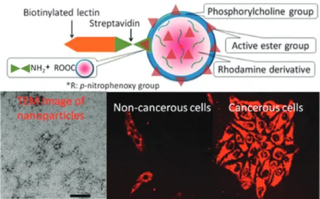
NPs made from organic monomers can be crosslinked to a various extent, and this determines many of their properties including swellability and solubility. The fluorescence of particles ato500 nm often interfered by autofluorescence of most cells. NPs prepared from hydrogels are biocompatible, cell permeable (depending, as always, on the zeta potential), nontoxic, slowly excreted, fairly quickly coated by intracellular proteins and attacked by the immunosystem. Many of them can be degraded by intracellular enzymes. Their surface cannot be easily chemically modified with additional coatings. Function- alities such as amino groups are better introduced by adding a functional monomer to the main monomer and then to initiate radical polymerization. Techniques are known to prepare organic polymer core–shell NPs. Fluorescent (and other) dopants tend to leach into the aqueous environment of the particle unless firmly retained (electrostatically or covalently). Amino-modified cellulose was applied in a luminescent sensor for high-resolution imaging of pHin vivo.28 pH values were imaged by detecting the green fluorescence of the pH probe fluorescein covalently linked to aminocellulose. A ruthenium phenanthroline complex was incorporated into poly-acrylonitrile beads to give a pH-independent red reference signal. The beads were immo- bilized in a polyurethane hydrogel on a thin transparent support.
Bothin vitroandin vivoexperiments revealed the versatility of the method during physiological and chronic cutaneous wound healing. The method was later extended to simultaneously image extracellular wound pH and oxygenationin vivo.29The same pH
beads were used, and poly(styrene-co-acrylonitrile) particles dyed with Pd(II)-meso-tetraphenyl-tetrabenzo-porphyrin were added to give a near-infrared signal that depends on local oxygen partial pressure.
A typical recent example of the use of a PAA hydrogel is provided by nanoparticles containing free amino groups that were prepared by copolymerization of acrylamide and methylene- bisacrylamide with 3-aminopropyl-acrylamide and labeling the terminal amino groups with pH probes such as fluorescein, Oregon Green, Alexa 633, and others. The resulting sensor NPs cover a wide range of pH (4.0–8.0) which is needed in certain situations even in cellular imaging.30 In addition to the widely used crosslinked polyacrylamides (PAAs), other acryla- mides including polymethacrylamide or poly(N-alkylacrylamides) were employed. For example, core–shell microgels containing indicators were fabricated31by two-stage free radical precipitation polymerization of N-isopropylacrylamide. The shell of the microgel exhibits a low critical solution temperature and undergoes a transition from a swollen state to a de-swollen state, associated with a hydrodynamic radius of B450 nm at 251C (in vitro) and ofB190 nm at 371C (in vivo). The microgel readily enters the cytosol which makes it a potential candidate for the delivery of indicator probes into the cytosol.
The Pluronict hydrogel (see above) was used to fabricate nanosensors for fluorescent imaging of physiological pH values.32 Features include (a) very small diameters (12 nm);
(b) biocompatibility due to the use of a hydrogel kind of material, and (c) the lack of toxicity. The nanosensors were incorporated into an agar film to enable continuous monitoring of the pH value of bacterial cultures, and thus of their growth.
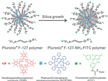
Dually responding nanosensor particles were reported that were prepared from an organic–inorganic composite (Pluronictrein- forced with silica) and used for simultaneous imaging of oxygen and pH in the cellular cytosol.33 Fig. 1 shows a schematic of the preparation of the dual nanosensor for oxygen and pH, the architecture of the NPs, and the chemical structures of the probes used. Other multiple (bio)sensors,i.e.sensors capable of two or more analytes simultaneously have been reviewed,34 but only a moderate fraction of them makes use of nanomaterials.
Nanogels (like NPs) are of interest in being extremely soft materials that take up water in fraction between 10 and 90%. The gels are well permeable to hydrophilic species and can be made fluorescent by simple labeling with inert labels and made responsive by attaching a fluorescent probe. Nanogel particles are well suited to image pH values inside cells.35 In a method termed CLARITY, nanoporous hydrogel-hybridized forms of intact mouse brain were prepared and crosslinked to a three-dimensional network of hydro- philic polymers.36 They are optically transparent and permeable macromolecules. Tissue imaging is said to reveal local circuit wiring, cellular relationships, subcellular structures, protein complexes, nucleic acids and neurotransmitters. CLARITY also enables intact- tissuein situhybridization, immunohistochemistry in non-sectioned tissue, and antibody labelling. Fluorophore-labeled polymeric nano- gels for sensing temperature (T) have attracted much interest because they pave the way to senseTinside cells. The topic has been extensively reviewed.37
Open Access Article. Published on 26 January 2015. Downloaded on 23/02/2016 15:32:51. This article is licensed under a Creative Commons Attribution 3.0 Unported Licence.
3.3. Hydrophobic organic polymers
Polystyrene nanoparticles (PS-NPs) are highly hydrophobic and can be doped with apolar fluorophores with emission peak wavelengths that range from the near UV to beyond 1000 nm.
Their color, decay times and size also are widely tunable.
Doping with lipophilic materials is preferred because ionic probes are poorly soluble in hydrophobic NPs from which the probes tend to leach out. As in all kinds of NPs for use in imaging, any fluorescence occurring at below 500 nm is inter- fered by the autofluorescence of biomatter. An (organic) dopant fluorophore can photobleach if exposed to strong laser light.
PS-NPs are fairly biocompatible (i.e., not harmful to cells and tissue), fairly well cell permeable, nontoxic, and their excretion is slow. If placed inside cells, they are only slowly coated by intracellular proteins and hardly attacked by the immuno- system. The modification of their surface is limited to certain functional groups. Functionalities (such as amino groups) are best introduced by the addition of co-reagents containing such groups to the monomer before starting emulsion polymeriza- tion. Post-modification and additional coating are rather diffi- cult. PS-NPs do not measurably swell in water and do not readily aggregate, but this depends on their charge and zeta potential. One of the first nanomaterials for sensing purposes consisted of (pH-insensitive) fluorescent PS beads coated with polyaniline whose absorbance is pH dependent over a large range of pH values. Depending on the actual pH value, the coating screens off the emission of the beads.38PS-NPs are well permeable to gases but impermeable to charged species includ- ing proteins. Particles with an average diameter of 85 nm were loaded with an oxygen-quenchable luminescent ruthenium complex and then used to image oxygen inside cells following 2-photon excitation.39
Polyacrylonitrile (PAN) NPs can be doped with fluorophores with emission wavelengths ranging from 300 to 1000 nm, preferably with hydrophilic dyes. Color, decay times and size widely tunable. Beads and aggregates of4300 nm in size cause light scattering. PAN is fairly biocompatible (not harmful to cells and tissue) and fairly well cell permeable, nontoxic, easily excreted but slowly coated by intracellular proteins. It is hardly attacked by the immunosystem. Its surface is rather inert and cannot be readily modified once the particles have been formed, usually by precipitation by adding water to a solution of PAN in dimethylformamide. PAN particles do not swell but there is a tendency to aggregation. Fluorophore-doped PAN-NPs were applied, for example, to referenced imaging of pH and temperature with sub-mm spatial resolution.40
Biocompatible fluorescent organic NPs with tunable photo- luminescence were obtained via one-pot oxidation of poly- dopamine and subsequently utilized for cell imaging,41 and water dispersible red fluorescent organic NPs for use in cell imaging were reported by Luo.42Quantum-dots conjugated to dopamine function as redox coupled assemblies and can be applied toin vitroand intracellular pH sensing.43Other polymers include poly(vinyl butyral)44that was labeled with a perylene dyes that is easily taken up without coating and does not display in vitro cytotoxicity on human cancer cells. Hu et al.45 have introduced a class of organic nanocomposites with function- alities for both fluorescence imaging and magnetic therapy.
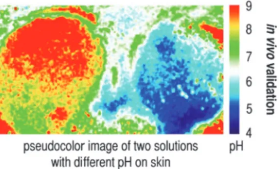
Magnetic NPs (5 nm in diameter) were incorporated into the amphiphilic block copolymer poly(styrene-b-allyl alcohol) that was labeled with pyrene. The fluorescence of the resulting NPs (200 nm i.d.) was exploited when imaging cancer cells, while magnetically controlled mechanical damage of cell membranes represents a way for cancer cell treatment referred to as magne- tolytic therapy. Magnetic field induced heating may pave, in future, the way to hyperthermal cancer therapy. This is schema- tically shown in Fig. 2. For numerous other examples, see Section 6.
3.4. Semiconducting (organic) polymer dots (P-dots)
These come in addition to more conventional (dyed) NPs such as those made from polystyrene, polyacrylamide etc.The polymer usually is prepared from aromatic precursors possessing polymer- izable double or triple bonds. Particles (as needed for imaging) Fig. 1 Structure of a nanosensor for dual sensing of oxygen and pH. Its
core consists of Pluronic F-127, a nonionic, surfactant triblock copolymer composed of a central hydrophobic chain of poly(propylene oxide) flanked by two hydrophilic chains of poly(ethylene glycol) (PEG) and reinforced with silica. The NPs are capped with PEG. The oxygen probe (PtTBTBP) and the reference fluorophore TFPP are located in the core, and the pH probe (FITC) is conjugated to the terminal ends of the PEG capping. Reproduced from ref. 33 with permission (2014) of the Am. Chem. Soc.
Fig. 2 Left: TEM of fluorescent organic nanobeads containing magnetic NPs. Right: bimodal use of the nanobeads for purposes of imaging cancer cells (top) and magnetically induced lysis of cell membranes. From ref. 45 with permission (2014) of the Am. Chem. Soc.
Open Access Article. Published on 26 January 2015. Downloaded on 23/02/2016 15:32:51. This article is licensed under a Creative Commons Attribution 3.0 Unported Licence.
are prepared by either emulsion polymerization or nano- precipitation.46 Doping with fluorophores is not needed. The backbone of conjugated polymers behaves like an array of light- harvesting units that exhibit a larger optical cross section com- pared to small organic molecule dyes. Photobleaching was not reported so far. Fine-tuning of the conjugated polymer structure and the polymeric encapsulation matrix leads to fluorescent probes with specific spectral properties and targeting capability.
P-dots display strong fluorescence that often extends far into the NIR, are highly inert and do not swell in water. Little is known about biocompatibility, internalization, and excretion from tissues.
Their uses in imaging and therapy have been reviewed.47 Fluorescent nanodots consisting of semiconducting polymer blends can be attached to peptides (such as chlorotoxin)48 and then can be used for targeted imaging (of malignant brain tumors, for example) in clinical diagnosis. By coupling the pH-indicator fluorescein to P-dots, a material is obtained that displays two fluorescence peaks, one being pH sensitive, the other not so that it can acts as an internal reference. Fully reversible pH sensing was demonstrated49 for the pH 5.0 to 8.0 range. Intracellular pH values were determined by imaging of HeLa cells following the uptake of the P-dots by endocytosis.
Tetraphenylethene-based fluorescent organic NPs undergo aggregation-induced emission inside cells and this was moni- toredviacell imaging.50The fluorescence of conjugated polymers, particularly if anionic, can be quenched by ions such as Cu(II).51 Semiconducting P-dots (20 to 50 nm) can also serve as photo- acoustic probes for real-time imaging of reactive oxygen species in living mice tissue where they accumulate quite readily.52
3.5. Carbon dots
Carbon dots (C-dots53), first reported in 2006, are said to be clusters of carbon atoms (for definitions see ref. 54) with dia- meters of typically 2 to 8 nm, but also contain substantial fractions of oxygen and hydrogen if not nitrogen. They do not measurably swell in aqueous solution but aggregation was occa- sionally observed. C-dots can be made strongly fluorescent and need not be doped or labeled. Their emission color can be tuned to some extent by varying the experimental conditions of synth- esis. Both the excitation and emission spectra are very wide and usually extend from the UV to the red (650 nm), a fact that virtually excludes their use in multiplexing. A fine review on the synthesis and photophysical properties (and uses in bioimaging) of C-dots is available.55 It includes the very true statement that
‘‘C-dots have a much more comprehensive definition compared to graphene quantum dots.’’ The QYs of C-dots range from 5 to 30%.
Fig. 3 shows the emission spectra of carbon dots at different excitation wavelengths from 330 to 475 nm. Their strongest fluorescence is blue, but longwave excitation (at 4460 nm) induces green to yellow emission. A review on the synthesis, properties and applications of C-dots contains an interesting section on the origins of their excitation wavelength dependent emission, and particularly the controversial upconverted lumi- nescence.56 The emissions also are likely to be pH-dependent.
Single-particle fluorescence intensity fluctuation (‘‘blinking’’) has been reported recently.57Decay times are in the nanosecond time
regime and do not vary much. The fluorescence of C-dots can be of the upconversion and the down-conversion type.
C-dots, and carbon nanoparticles in general, can be single- photon excited and multi-photon excited. C-dot-based inorganic–
organic nanosystems were applied, for example, to two-photon imaging of pH variation in living cells and tissues.59C-dots are fairly well biocompatible (i.e., not harmful to cells and tissue within a few days), fairly well cell permeable, not known to be toxic, easily excreted, weakly interacting with proteins, and hardly attacked by the immunosystem. Functional surface engineering for purposes of bioconjugation and imaging is more difficult than in the case of Q-dots but possible.60They neither swell nor photobleach. Their fluorescence is pH dependent and quenched by iodide61 (and probably by other notorious quenchers too).
A recent review covers the subject.62
In terms of synthesis, both top-down and bottom-up approaches are known. The resulting C-dots, in fact, always contain substantial fractions of oxygen (up to 50%) and also nitrogen if a nitrogen-containing substance such as an amino acid is added during synthesis. And yet, they are often termed – mainly by Chinese authors – graphene quantum dots even though graphene by definition consists of C and H only and is nonfluorescent. Examples where the application of ‘‘graphenes’’
is claimed but materials other than sp2-graphenes have been used include, for example, intracellular fluorescence imaging with a ‘‘graphene’’-based fluorescent probe,63 and the use of highly biocompatible ‘‘graphene’’ nanosheets for cellular imaging.64 A particularly confusing example is represented65 by an article entitled The in vivo and in vitro toxicity of graphene quantum dotsthat has nothing to do with graphene (which is free of oxygen by definition and non-fluorescent). The authors have prepared the highly fluorescent (!) graphene material by oxidation (!) and also claim it to possess a particularly high oxygen content (!).
C-dots have been prepared from numerous organic materials and natural products containing carbon in various form, one example being58the preparation of 3 nm blue fluorescent C-dots from cow milk by heating it to 1801C for 2 h. The particles can be Fig. 3 Wavelength dependence of aqueous solutions of carbon dots in water at excitation wavelengths between 330 and 475 nm. Reprinted from ref. 58 with permission (2014) of the Am. Chem. Soc.
Open Access Article. Published on 26 January 2015. Downloaded on 23/02/2016 15:32:51. This article is licensed under a Creative Commons Attribution 3.0 Unported Licence.
used to image U87 cells. If C-dots are doped with nitrogen,66they are even more strongly fluorescent. Both hydrophilic and hydro- phobic C-dots are known. Hydrophilic materials are preferred in imaging.67Hydrophobic materials are less often used but also available by microwave synthesis.68Raw C-dots are mainly pre- pared by microwave induced thermal carbonization of molecular precursors such as glucose (and other carbohydrates), citrate, (poly)glycols, often in the presence of a nitrogen source (such as tryptophan or EDTA). Surface passivated (und, therefore, bright) C-dots can be directly synthesized by microwave induced pyrolysis of glycerol in the presence of 4,7,10-trioxa-1,13-tridecanediamine.69 C-dots can also be isolated from soot, or prepared from glucose with P2O5at room temperature.70 C-dots may be rendered to more strongly fluorescent by alkali or acid-assisted ultrasonic treatment.71
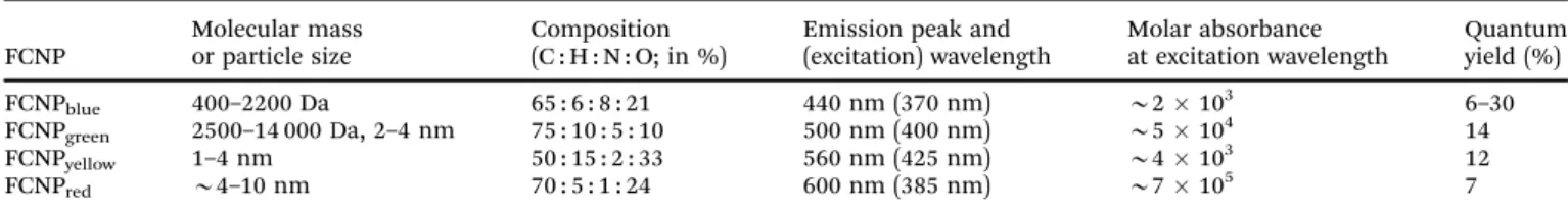
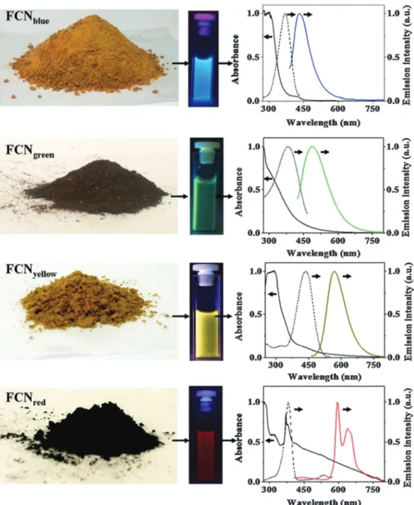
Photoluminescent C-dots have also been produced by laser ablation of graphite followed by oxidation with nitric acid and functionalization with diamine-terminated poly(ethylene glycol).72 They show multicolor fluorescence.73 C-dots can be produced inexpensively and on a large scale. Fluorescence is conferred or improved by chemical treatment (or passivation) of the surface, for example by oxidation, doping with inorganics, or capping. Water dispersible C-dots with tunable photoluminescence can also be synthesized74 viahydrothermal oxidation of nanodiamonds and were subsequently utilized for cell imaging. Carbon nanoparticles (10 nm i.d.) for use in fluorescent bioimaging can be obtained now75on the milligram to gram scale by carbohydrate carboniza- tion (even though in our experience this method is difficult to reproduce not the least because of an inadequate experimental part). Table 1 gives examples of CNPs (prepared on the gram scale) along with colors of emission (from blue to red). Red-fluorescent CNPs are preferred because autofluorescence of biomatter is weaker in this spectral range (Fig. 4).
Both C-dots with invariable and with continuously tunable emission are known.76 They enable ratiometric sensing of pH values via the ratio of the intensities of the excitation- independent and pH-independent blue emission and the excitation-dependent and pH dependent full-color emissions.
Ratiometric (blue and green) fluorescent nanosensors have been described77 that are based on water soluble carbon nanodots with multiple sensing capacities. This, however, is an euphemism for poor selectivity in that the dots respond to temperature, pH, and to Fe(III) ions, all of which mutually interfere.
3.6. Other carbonaceous materials
Other nanosized carbon allotropes include fullerenes (C70
mainly; these being much smaller than C-dots), and the larger
species including carbon nanotubes (CNTs; single walled and multiwalled), nanodiamonds, graphene (which is nonfluorescent), and the oxidized species graphene oxide, reduced graphene oxide, graphite oxide, graphene quantum dots (often synonymously used for C-dots; see Section 3.5.) and the like. Other authors refer to their materials as graphene (or graphene dots) even if the material was prepared by reduction of graphite oxide (by Hummers method) and still contains large fractions of oxygen. It may be better termed ‘‘reduced graphite oxide’’. There is much confusion.
The fluorescence of graphite oxide78(like that of C-dots79) is sensitive to pH. Like C-dots, such carbon nanomaterials need not be doped with fluorophores and are extremely photostable.
The colors of emission of all known variants depend on the wavelength of excitation. Excitation in the UV (350–380 nm) often results in good brightness and blue fluorescence, but excitation wavelengths can be as long as 650 nm and fluores- cence then occurs in the near IR as is shown below. The decay times of fluorescence are in the order of nanoseconds. Nano- sized fluorescent graphite oxides (nano-GOs) with different size distribution were prepared via a one-pot hydrothermal route using ultra-small graphite powder as a starting material and subsequently separated using dialysis tubes with different molecular weight cutoff.80 Such nano-GOs were found to be readily internalized by A549 cells and then located in the cytoplasm. They display size-dependent photoluminescence (green, yellow, red) and excellent biocompatibility.
Graphene81 and (color-tunable) fullerenes82 have not often been used for purposes of imaging because of their lack of (or rather weak) fluorescence. Fullerene C70(unlike C60which is nonfluorescent) displays normal and delayed fluorescence which is strongly quenched by oxygen83and highly dependent on temperature.84 Gonget al.85 have isolated red, green and blue fluorescent hollow carbon NPs from chromatographic fractions and demonstrated them to be excellent (multi-color) probes for cellular imaging.
Stabilized graphene oxides were applied to cellular imaging,63 some after having been made highly biocompatible86or stabilized and biofunctionalized.87Blue and green fluorescent carbon NPs derived with vitamin B1 are also described to be very bright and applicable to cell imaging.88Luoet al.have reviewed applications of carbon-based quantum dots for fluorescence imaging of cells and tissues.89Fluorescent graphene quantum dots (GQDs) have been synthesized90that display both upconverted and excitation- independent downconverted photoluminescence. Doping of GQDs with almost any kind of heteroatom including nitrogen,91 boron,92 sulfur,93 fluorine94 and chlorine95 enhances their brightness. By coupling them to photocatalytically active rutile
Table 1 Properties of fluorescent carbon nanoparticles (FCNPs) with blue, green, yellow and red emission; containing between 10 and 33% oxygen and 1 to 8% of nitrogen. From ref. 75
FCNP
Molecular mass or particle size
Composition (C : H : N : O; in %)
Emission peak and (excitation) wavelength
Molar absorbance at excitation wavelength
Quantum yield (%)
FCNPblue 400–2200 Da 65 : 6 : 8 : 21 440 nm (370 nm) B2103 6–30
FCNPgreen 2500–14 000 Da, 2–4 nm 75 : 10 : 5 : 10 500 nm (400 nm) B5104 14
FCNPyellow 1–4 nm 50 : 15 : 2 : 33 560 nm (425 nm) B4103 12
FCNPred B4–10 nm 70 : 5 : 1 : 24 600 nm (385 nm) B7105 7
Open Access Article. Published on 26 January 2015. Downloaded on 23/02/2016 15:32:51. This article is licensed under a Creative Commons Attribution 3.0 Unported Licence.
(TiO2/GQD) and anatase (TiO2/GQD) systems, the complete visible spectrum of sunlight can be harnessed. Strong two- photon-induced fluorescence was reported96 for photostable, biocompatible nitrogen-doped graphene quantum dots (N-GQDs; possibly C-dots?) for cellular and deep-tissue ima- ging. Their two-photon absorption cross-section reaches 48 000 Go¨ppert-Mayer (GM) units, which far surpasses that of many organic dyes. It is comparable to that of the high performance semiconductor Q-dots and represents the highest value ever reported for carbon-based nanomaterials. The penetration depth in phantom tissue revealed an imaging depth as deep
as 1.8 mm. Zhu et al.97 have presented a study on surface chemistry based routes to modulate the photoluminescence of GQDs, how to govern the fluorescence mechanism to induce up-conversion fluorescence, and on bioimaging applications.
Single-walled and multi-walled CNTs are fluorescent in the NIR but have low quantum yield.98 The one-dimensional electronic structure of nanotubes results in sharp interband transitions in the absorption spectra of SWNTs, and in photo- luminescence in the NIR region (800–1600 nm). These wavelengths include the tissue-transparent region of the electromagnetic spec- trum. Their other properties are comparable to those of C-dots.
Fig. 4 Images of gram scale solid samples of fluorescent carbon nanoparticles (FCNPs), of their solutions under appropriate excitations, and their absorption (—), excitation ( ) and emission (color lines) spectra. Emission spectra have been measured by exciting at 370 nm for FCNPblue, by exciting at 400 nm for FCNPgreen, by exciting at 425 nm for FCNPyellowand by exciting at 385 nm for FCNPred. From ref. 75 with permission (2014) by Nature Publ. Group.
Open Access Article. Published on 26 January 2015. Downloaded on 23/02/2016 15:32:51. This article is licensed under a Creative Commons Attribution 3.0 Unported Licence.
Like C-dots, they do not photobleach. While traceable in living cells, their cytotoxicity is still not refuted,99,100 but carbon nano- tubes encapsulated by a DNA oligonucleotide remain functional in live cells for up to three months.101CNTs have been applied to Raman imaging, near-infrared (NIR) fluorescence imaging and photoacoustic imaging but still are less often used than some other fluorescent nanomaterials. The group of Strano102 has reviewed advances in molecular recognition based on single- walled CNTs and respective nanoengineered platforms. These were used to fluorescently sense species such as ATP, NO, H2O2, and glucose in cells.
Three-dimensional tracking of single-walled CNTs with an orbital tracking microscope was demonstrated.103The technique was applied to determine the viscosity regimes within live HeLa cells, and this was used to spatially map corral volumes (0.27–
1.32mm3), to determine active transport velocity (455 nm s 1), and to calculate local viscosities (54–179 cP) within the cell.
The NIR emission of CNTs (with their second window at 950–
1400 nm) is attractive forin vivofluorescence imaging due to its deep penetration depth in tissues and low tissue autofluores- cence. Genetically engineered multifunctional M13 phages were shown to assemble single-walled CNTs and ligands for targeted fluorescence imaging of tumors.104
Nanodiamonds (NDs) are being produced, as powders, by detonation synthesis on a commercial scale. They have low or no cytotoxicity.105,106NDs doped with nitrogen are particularly bright. Synthetic NDs form fluorescent centers by thermal annealing and then have rather longwave peaks of excitation (B560 nm) and emission (B700 nm). The intrinsic red fluores- cence is strong enough to detect a single 35 nm ND in a cell.107 Others types of NDs possess green fluorescence (peaking at 531 nm) and represent a promising alternative to semiconduc- tor quantum dots (see above) because they are photostable, hardly toxic, easily excreted, and can be fairly easily bioconju- gated. Hydrophobic derivatives of NDs possessing blue emis- sion have been obtained by modifying the surface with long- chain alkyl groups.108NDs do not swell, and their size can be hardly tuned by chemical means.
3.7. Metal chalcogenide quantum dots (classical Q-dots) These are typically made from combinations of zinc(II), cadmium(II), selenide and sulfide. Numerous additional compo- nents and dopants are known, and sophisticated methods have been developed to modify surfaces and to create additional shells. Q-dots have experienced an unprecedented success in imaging because of their unique properties. They need not be doped with fluorophores because their fluorescence results from a photonic quantum effect. The color of emission and their size are well tunable and interdependent. Decay times (in the low ns time domain), in contrast, do not vary much. Q-dots display Gaussian emission spectra (with FWHMs of typically 30 nm) and therefore have multiplexing capacity (like upconverting NPs but unlike C-dots). All Q-dots require photoexcitation at o500 nm where biomatter often strongly absorbs (this causing an inner filter effect), and fluorescence intensity strongly varies over time (‘‘blinks’’; however, non-blinking Q-dots have been
described recently). The quantum yield (QY) of Cd/Zn based Q-dots is rather high (0.3–1.0) which is distinctly better than the QYs of upconversion NPs (see Section 3.8), for example. Dots and aggregates of4300 nm in size cause strong light scattering.
Single photon, 2-photon, and recently,1093-photon excitation and imaging have been demonstrated, and cross sections can be as large as 60 000 GM units.
Q-dots are cell toxic unless coated with inert shells, but passivation and reduced toxicity of CdS dots also were accom- plished by coating them with DNA.110They are fairly well cell permeable but clearance from tissue is difficult, partially because of their interaction with thiol groups of cysteines in proteins.111 Their surface chemistry is well established, and several kinds of surface-modified Q-dots are commercially available. They do not swell or photobleach but fluorescence depends on temperature. They are uniquely suited for high resolution and multiplexed imaging of cells. Good reviews cover aspects such as on applications to fluorescence spectro- scopy and imaging,112rendering them biocompatible,113on the cytotoxicity of cadmium-based Q-dots,114 or on nucleic acid- passivated Q-dots acting as biomolecular templates of varying form and function.115Recent work includes the application of Q-dot nanosensors to fluorescence lifetime imaging micro- scopy of intracellular pH,116or of Q-dots loaded with fluores- cent liposomes in order to perform fluorescence resonance energy transfer studies and NIR in vivo imaging of mouse tissues.117 The fluorescence decay time of Q-dots becomes pH-dependent on coating them with NIR fluorescent dyes.118 The fluorescence of certain Q-dots is quenched by Zn(II) and Cd(II) ions,119 and this paves the way for imaging such ions intracellularly. Q-dots may additionally be doped with other metal ions to give, for example, brightly fluorescent Mn-doped ZnS, Mn-doped ZnSe, or Cu-doped InZnS particles (10–80 nm in diameter) which represent a new class of fluorescent nano- particles with low toxicity.120
Aside from Q-dots composed of Zn(II), Cd(II), sulfide and selenide there are numerous other kinds of such particles. It is difficult to keep track with the variety of materials that have been presented in recent years. NPs with quantum effects can also consist of group III–V elements. Some are brightly fluorescent, one example being InP Q-dots functionalized with a Ln(III) chelate and coated with a cell-penetrating peptide for use as bimodal imaging agents (MRI and confocal microscopy).121The reader is referred to some of the many reviews that exist on the use of Q-dots in bioimaging. Also see Tables S1–S5 in the ESI.†
3.8. Upconversion nanoparticles (UCNPs)
Most UCNPs (also referred to as upconversion nanocrystals) consist of hexagonal NaYF4 nanocrystals doped with trivalent lanthanide ions such as Er(III), Yb(III) or Tm(III). The dopant is the emitter and additional doping with fluorophores is not needed. UCNPs display several emission colors (with at least two strong bands in the visible) whose peak wavelengths depend on the kind of lanthanide dopant. However, single color emitting UCNPs of the NaYbF4 type and emitting in the green,122red123and NIR,124or consisting of lanthanide-doped Open Access Article. Published on 26 January 2015. Downloaded on 23/02/2016 15:32:51. This article is licensed under a Creative Commons Attribution 3.0 Unported Licence.
KMnF3 nanocrystals have also been reported.125 The size of UCNPs is widely tunable (typical sizes ranging from 10 to 100 nm) and affects quantum yields. The control of size and of the emission and excitation spectra is still a challenge.126The fact that most UCNPs display multi-photon (bicolor) emissions also paves the way to increased resolution in microscopy.127Their dual (or multiple) emissions often enable referenced (2-wavelength) sensing and imaging but unfortunately the ratio of the two emissions (often green and red) varies with the coating and undergoes a change if hydrophobic particles of the oleate type are converted into hydrophilic particles (as preferably used in bioimaging). The use of upconversion NPs in bioimaging, therapy, drug delivery and bioassays has been reviewed.128Very recently it was shown129 that coating UCNPs with a layer of silver causes metal-enhanced (plasmon) upconversion and a 30-fold increase in brightness compared to NPs without the silver core. The NPs used for imaging of HeLa cells have a 3-layer core–shell–shell architec- ture of the type Ag@SiO2@Lu2O3:Gd,Yb,Er. The silver induced plasmon enhancement mechanism in NaYF4:Yb,Er NPs (Maxwell versusFo¨rster) was studied in some detail.130
Unlike in the case of carbon dots, the color of the emission of UCNPs is independent of the excitation wavelength which is rather longwave (750–1000 nm). UCNPs with oleate capping (as obtained by the most popular method of synthesis) possess moderate brightness only, but those modified with hydrophilic coatings are much less bright, with QYs that hardly exceed 0.5%
in water solution. QYs of 1–3% have also been reported but only for bulk materials or for dried and aggregated particles. The seemingly poor QYs of UCNPs are still acceptable because their anti-Stokes emission allows fluorescence images to be acquired against a black background.
Remarkably, and unlike in the case of Q-dots, the QYs of UCNPs also depend on the power density (Watt cm 2) of the (cw) laser and on particle size, with smaller particles of the same kind displaying smaller QYs.131 It is reminded that the QY of UCNPs is poorly defined.132If data are given, it shall also be stated whether these refer to a single emission band or the total emission (in either Stokes and anti-Stokes mode). In addition, the size of the particles investigated must be given along with power density, and how the inner filter effect of water solutions (under 980 nm excitation) has been taken into account. UCNPs, if coated with a shell of undoped NaYF4(and even silica), are much brighter in water than uncoated UCNPs. The group of Resch-Genger133has determined, in a solid study, the QY of oleic acid-coated UCNPs of type NaYF4:Yb,Er to be 0.35% under well defined experimental conditions. Gargaset al.134 report on seemingly highly attractive nanocrystals (5–8 nm i.d.) for single-molecule imaging. The brightness under single-particle imaging conditions is said to be much higher than that of other compositions. However, the power density applied in the experi- ments is as high as4106W cm 2which is hardly tolerated by any living organism. If such a power density is applied to watery samples, strong local heating will occur. In fact, if excited with conventional power density, the luminescence of these UCNPs is so weak that no spectra can be acquired.
UCNPs may also be applied to optically encode and to multiplexed imaging of cells and microspheres.135The method
may be extended to lifetime-based encoding by exploiting their tunable luminescence lifetimes which are in the microsecond time regime in case of NaYF4:Yb,Tm.136By exciting a single color band, one can generate more than ten excited state populations with lifetimes ranging from 25.6 ms to 662 ms and decode their well-separated lifetime identities which are independent of both color and intensity.
Host crystals other than NaYF4 have been studied recently.
Light management in UCNPs was demonstrated for ultrasmall NaGdF4nanoparticles core–shell architectures to tune their emis- sion color.137In another example,138the brightness of core–shell nanocrystals (NaLuF4:Gd,Yb,Er coated with a shell of NaLuF4:Yb) was found to be remarkably higher than that of inert-shell coated nanocrystals. These particles can be used to image HeLa cells.
Even more complex UCNPs of the type NaLuF4:Gd,Yb,Er were synthesized recently and applied to bioimaging.139
UCNPs are perfectly suited for bioimaging because fluores- cence is not at all interfered by the autofluorescence of cells.140 Moreover, they are fairly biocompatible and – if small enough – cell permeable.141 They are not known to be toxic and easily excreted. They usually are weakly interacting with proteins but can be well conjugated to them.142,143UCNPs are hardly attacked by the immunosystem, and their surface can be easily modified.
They do not swell but tend to aggregate in the presence of bivalent ions. Photobleaching cannot occur. Their luminescence is highly dependent on temperature144and (rather unselectively) quenched by several heavy metal ions.145 It is reminded that photoexcitation of UCNPs with lasers of wavelengths above 800 nm can lead to local heating which can represent a sub- stantial source of error in quantitative fluorometry.
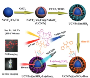
If excited with NIR lasers, UCNPs heat up. This can be desired or not. It is not desired in the case of bioimaging, and an excitation wavelength of 915 nm was recommended to reduce laser induced heating of UCNPs of the type NaYbF4: Tm,Er,Ho for deeperin vivoimaging.146Heating may, however, also be desired because local heating can be exploited in cancer therapy. In a typical application, oleate-capped UCNPs were coated first with a shell of plain silica (also in order to make them more stable in water solution) and then with a layer of silica doped with a blue carbocyanine dye. The optical emission of the upconverting NP was absorbed by the dye to cause a local heating by up to 211C and this causes cells to disrupt. Fig. 5 shows a schematic of the preparation of such UCNPs and respective TEMs. Even shorter excitation wavelengths can be used as shown147with core–shell UCNPs doped with Nd(III) ions as sensitizers. The upconversion effect already occurs at excita- tion wavelengths of around 800–820 nm, and this can strongly reduce sample heating and overtone IR absorption by water.
Others have shifted the excitation wavelength for upconversion to 1490 nm by using LiYF4:Er nanocrystals.148
Most syntheses yield water-insoluble NPs which first have to be surface-modified so as to enable phase transfer to aqueous solu- tions. Reviews are available on the design, nanochemistry and applications of UCNPs in theranostics,149on the surface chemistry of UCNPs, and how to make them hydrophilic.150 Any surface modification has, however, an effect on their luminescence and Open Access Article. Published on 26 January 2015. Downloaded on 23/02/2016 15:32:51. This article is licensed under a Creative Commons Attribution 3.0 Unported Licence.
colloidal properties.151The upconversion fluorescence of NPs of the type Ag@SiO2@Y2O3:Er can be fine-tuned by the size of the silver core.152 The emission color of lanthanide doped NaYF4
UCNPs also changes during the transformation of crystalline phases froma, a transition state ofa mixed withb, and finally to theb phase (from red to yellow and finally to green). Coated with polyethyleneneimine, such particles were used to image cells.153
Examples for applications include the kinetic determination of the activity of the enzyme phospholipase.154A mixture of a PEGylated phospholipid and a rhodamine-labeled phospholipid was deposited on an UCNP composed of hexagonal NaYF4doped with 20% Yb(III) and 2% Er(III). The 540 nm emission of the UCNP is used to photoexcite rhodamine B close to the NP. If, however, the phosphodiester is hydrolyzed by the enzyme phospholipase inside a cell, the rhodamine is released from the surface of the UCNP, and this leads to the suppression of the fluorescence of the rhodamine. The red emission peaking at 655 nm is not affected by this process and can serve as an internal standard.
Earlier work in the use of UCNPs in chemical sensing and biosensing has been reviewed.155 A recent review covers their application to bioassays and bioimaging.156
3.9. Noble metal nanoparticles
Specific features of such NPs include excellent photostability, water-solubility, size-dependent colors, the lack of swelling, sharp contrast, the ease of characterization by means such as TEM or SEM, and an established surface chemistry (often thiol-based) which is useful if targeted imaging or biosensing/imaging is desired. The uptake of engineered gold nanoparticles by mam- malian cells has been reviewed by Dykman and Khlebtsov.157 Gold and silver NPs can also be coupled to plasmonic detection quite readily or used to generate fluorescence patterns through differential release of fluorescent polymers.158
Single gold or silver NPs display rather weak fluorescence but were used to image HeLa cells.159 While one-photon
luminescence is weak, two-photon luminescence of gold NPs is strong under excitation at 514 and 633 nm.160 Two-photon luminescence imaging of cancer cells down to 75mm depth and using molecularly targeted gold nanorods161and of silver NPs162 has been reported. On the other hand, gold NPs can quench fluorescence by phase induced radiative rate suppression.163 It was relatively late when it was discovered that metal clusters made from metallic gold, silver, copper, for example, display strong intrinsic fluorescence.164 Noble metals are preferred for their inertness. The surface of these clusters (gold and silver in particular) can be protected with alkanethiolate monolayers. If properly modified, they enable plain imaging and targeted imaging. While luminescence is often attributed to particle size effects that cause size-dependent fluorescence,165structural para- meters such as surface ligands, valence states of metal atoms and crystallinity of NPs also affect spectra and decay times. Gold NPs and clusters can be composed of a few to millions of atoms.166 Such ‘‘quantum’’ clusters may also be protected or made targe- table by coating them with respective proteins.167For example, gold NPs were functionalized with luminescent ruthenium(II) polypyridyl to endow DNA binding capability and applicability to cellular imaging.168These structures bind to DNA and undergo rapid cellular uptake, being localized within the cell cytoplasm and the nucleus within 4 h. Various kinds of fluorescent silver nanoclusters (with green, red and yellow luminescences) have been reported by Dı´ez et al.169 In a smart sensing approach towards probing phosphate ions,170gold nanoclusters (NCs) were capped with 11-mercaptoundecanoic acid and loaded with Eu(III) ions. The red fluorescence of the gold NCs is quenched by the Eu(III) ions, but fluorescence is restored upon addition of phosphate.
3.10. Dendrimers, lipid drops and micelles
Dendrimers (dendrites) are a kind of NPs but much smaller than those treated so far. They can be both hydrophilic and hydro- phobic and are easily internalized by cells. Their fluorescence Fig. 5 (A) Preparation of UCNPs for use in imaging and hyperthermal cancer treatment. (A) Coating of the green UCNPs first with silica and then with silica doped with the blue and NIR emitting dye Cite-777. (B–D) TEM images of the UNNPs, UCNP@SiO2core–shell particles, and UCNP@SiO2particles coated with the dye–silica nanocomposite. From ref. 146 with permission.
Open Access Article. Published on 26 January 2015. Downloaded on 23/02/2016 15:32:51. This article is licensed under a Creative Commons Attribution 3.0 Unported Licence.