J. Perinat. Med.
4 (1976) 184
A fluidic-controlled, miniature respirator with a new positive airway pressure device
G. Simbruner, M. Baum
Department für Neonatologie und angeborene Störungen (Head: Prof. Dr. 0. Thal- hammer) der Univ. Kinderklinik Wien
'
xContinuous positive airway pressure (CPAP) has proved to be a very helpful tool in the treatment of RDS [l, 2, 3]. In many cases the improvement in gas exchange äs well äs in lung mechanics, which can be achieved by CPAP, is sufficient to substitute for artificial Ventilation [4, 5]. This method has also become a valuable technique for weaning patients from the respirator. Since its introduction by Gregory many modified CPAP devices have been constructed. Their development shows a tendency (a) to simplify the devices and (b) to make them safer [6, 7, 8]. The conventional CPAP-apparatus is rather large, bulky and compli- cated for use with premature infants. The tubing and apparatus hinders the general management of the patient and prevents transport. A large dead- space endangers sufficient alveolar Ventilation. A conventional CPAP-system does not allow imme- diate transition to other forms of ventilatory assistance äs provided by respirators i.e. that a rapid change from CPAP to IPPV is not possible with Systems in use. nowadays. There are only very few pediatric respirators that really can cope with the specific demands of artificial Ventilation of the newborn [9, 10]. Common to all existing pediatric Ventilators is a rather complicated hand- ling, a very complex electronic or pneumatic circuitry which is difficult to deal with [11] and last but not least a high price. It would therefore be very useful to have a simple apparatus for däily use, which included all the respiratory modes
Curriculum vitae
GEORG SIMBRUNER:
born in 1945. Study of medicine in Vienna. 1970 Medical doctör. For 2years clinical assistant at Univer- sity of Stellenbosch, South Africa. Since 1973 working in the Department ofNeo- natology, Prof. Dr. O.
THALHAMMER. Main fields of interests: respi- ration and circulation of the newborn, especially cybernetic Systems and machines.
mentioned above with a maximum of simplicity and reliability.
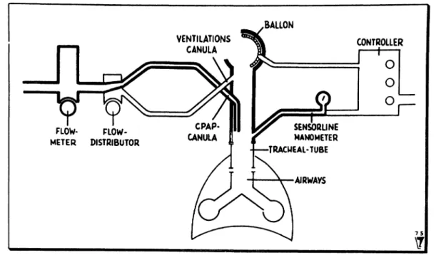
We developed a simple and versatile respirator of miniature dimensions. According to the morpho- logical structure the respirator consists of twp Systems: one to supply the air and the other to control it (Fig. l a and l b).
l. l Air-supply System
It contains a flow-meter, a fio
viy-divider and a part
called the regulator. The regulator is a tube with
the same diameter äs the tracheal tube fitted with
one end onto it. The other free end of the regulator
can be occluded by a valve-mechanism. 1t consists
of a balloon, which occludes the tube when inflated
Simbruner et al., Respirator with a new positive airway pressure device ' 185
BALLON VENTILATIONS
CANULA CONTROLLER
O O O FLOW- FLOW-
METER DISTRIBUTOR
SENSORLINE MANOMETER TRACMEAL-TUBE
AIRWAYS
Fig. l a. Principal structure of the apparatus. Parts needed for CPAP in heavy print.
15
T
Fig. Ib. Principal structure of the apparatus. Parts needed for mechanical Ventilation in heavy print.
and does not offer any resistance tp expiration when deflated. Two canulas are fitted into the lumen of the regulator: one is parallel pointing in the direction of the lung (CPAP-canula), the other points to the open end of the tube at a small acute angle (Ventilation-canula).
1.2 Control-system
It comprises a sensor-line connected to a mano- meter and the so-called "Controller", which con- sists of fluidic-circuits [12]. The sensorline has to enter the tracheal-tube at least 3 cm below the
J. Perinat. Med. 4(1976) 13*
pressure due to the Venturi effect. The sensorline feeds Information about the tracheal pressure changes into the fluidic-circuits the Output of which controls the balloon. Thus the control System functions äs a feed-back-loop. The fluidic circuit is constructed to provide controlled Ventilation and to guarantee safety by a pressure limiting device.
600 liters of pressurized gas are needed to operate the fluidic circuits for half an hour.
According to the function we distinguish between a CPAP-system and one for mechanical Ventilation.
Both can be combined. By definition CPAP is then calledPEEP[13].
2.1 CPAP-system
\Fig. l a shows the necessary parts (in heavy print):
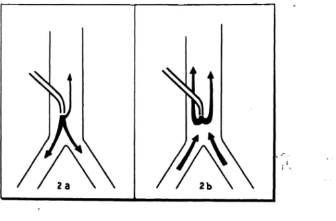
flowmeter, CPAP-canula of the regulator and manometer. An oxygen-air-mixture rationed by the flowmeter passes through the CPAP-canula into the airways. Because the preset flow is greater than the volume ventilated per minute, a part of this flow escapes even during the inspiratory phase at the open end of the regulator. During expiration the direction of the insufflated air has to be changed by the patient's expiratory flow and the dynamic pressure necessary for it manifests itself äs a constant positive airway pressure. The airflow
desired CPAP äs indicate4 by the manometer. The distribution of flow during the breathing cycle can be seen in Fig. 2a (Inspiration) and 2b .(expiration).
2.2 System for mechanical Ventilation
In this mode the airsupply- and the contröl-system are necessary for Operation (Fig. l b in heävy print).
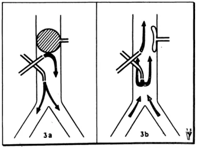
As mechanical Ventilation can be combined with a positive airway pressure we choose to describe the combined function. The inspiratory flow is set on the flowmeter. The flow-divider divide$ it into two partial flows: one passes through the CPAP-canula, the other through the Ventilation cariüla. The divi- sion is made to obtain a flow through the CPAP canula resultirig in the desired positive airway pressure. Cönsequently the remaining flow passes through the Ventilation canula and leaks into the open air without any effect äs long äs the valve- mechanisni is open. The moment the valve- mechanism closes due to the inflating of the balloon, the total flow is directed into the lungs.
Inspiration lasts äs long äs the balloon occludes the cross-section of the regulator. When it collapses, expiration begins during which the flow through the CPAP-canula keeps üp a positive airway pres- sure. For flow distribution see Fig. 3 a (Inspiration) and 3b (expiration). CPAP and inspiratory flow
u
Fig. 2 a, 2b. Flow distribution during CPAP assisted Ventilation a) at Inspiration, b) at exspiration.
Simbruner et al., Respirator with a new positive airway pressure device 187
can be regulated independently by flowmeter and flow-divider. Frequency and durationof Inspiration (I:E ratio) can be set on the Controller. The venti- lating volume delivered is dependent on inspiratory flow and I:E ratio, äs in all respirators of the
"constant-flow-generator"-type äs long äs the preset safety-pressure is not reached. The control modes are time cycled/pressure limited or pressure cycled/time limited.
2.3 Sighing
A slight modification allows sighing in an open System. It can be brought about by allowing the airflow used for inflating the balloon to pass through the CPAP canula. The airflow must be sufficiently great to create the pressure necessary for hyperinflation. It is also possible to combine sighing with CPAP.
3 Methods
3.1 Test with a lung model
The lung model used in our experiments consisted of a 5 litre glass bottle filled with 2 litres of water thus giving a compliance of 3 ml/cm water (in- dependent of respirator pressure and — rate). A tracheal resistance of 20 cm water/1/sec was simu- lated by an orifice connected to the neck of the
bottle. Airway pressure was recorded by means of an electromanometer. Under these conditions measurements were made to optimize different variables like diamter of the regulator, velocity and angly of inflow and pressure-rise-velocity (dp/dt).
3.2 Clinical Tests
The CPAP device was tested on an anencephalic newborn, 3 days of age, 2800 g, with clinical signs of dyspnoea to obtain flow-pressure-ratios. CPAP and mechanical Ventilation with PEEP were tested on a 3 months old baby, 4 kg, during the postop- erative phase after a partial correction of an anom- alous pulmonary venous drainage had been per- formed. The pressure curves were obtained from the tracheal tube at a distance of 7 cm from the mouth.
4 Results
4. l Lung model results
The variables which affect the amount of CPAP produced were found to be:
4.1.1 Diameter of the tube Table I shows that CPAP is inversely correlated to the diameter of a tube and flow dependent.
Fig. 3 a, 3b. Flow distribution during mechanical ventüation with PEEP a) at Inspiration, b) at exspiration.
J. Perinat. Med. 4(1976)
2 mm3 mm 4 mm
3010 4
4018 8
cm water diameter
0.9mm 1.5 mm
3r 3.51.5
6 24.59.5
litres/min.
ein wat er
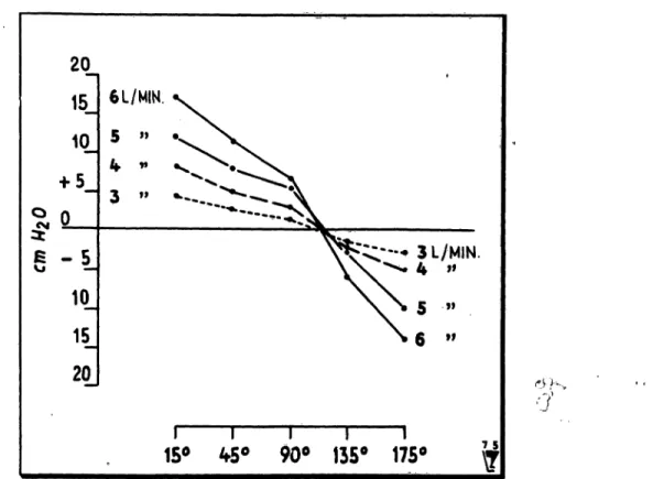
4. l .2 Angle of inflow
A correlation was found between the pressure in a tube, obtained by an airflow through a canula, and the angle of inflow, with its maximum (and positive value) when directed towards the lung and its mini- mum (and negative value) when directed oppositely (Venturi effect) (Fig. 4).
4.1.3 Velocity of inflow
The thinner the canula (i.e the greater the flow velocity) the higher the CPAP produced. Canulas with a diameter of 0.8 mm or less have a very high resistance and the driving pressure neces- sary to obtain a certain flow velocity mäy enhence disconnection of the tubing. The results with a set of these variables are shown in Tab. H.
4. l .4 Piessure-rise-velocity (dp/dt)
For a sighing manoevre it is necessary to obtain a certain pressure within a certain periöd of time.
Fig. 5 shows pressure-time curves at varioüs flow- rates, in a 3 mm wide tube. The inflow is parallel to the tube, the canula diameter 0,9 mm. At flow- rates ranging from 3 to 7 litres/min 90% of the maximum pressure cäri be achieved within 0.5 sec.
4.2 Clinical results
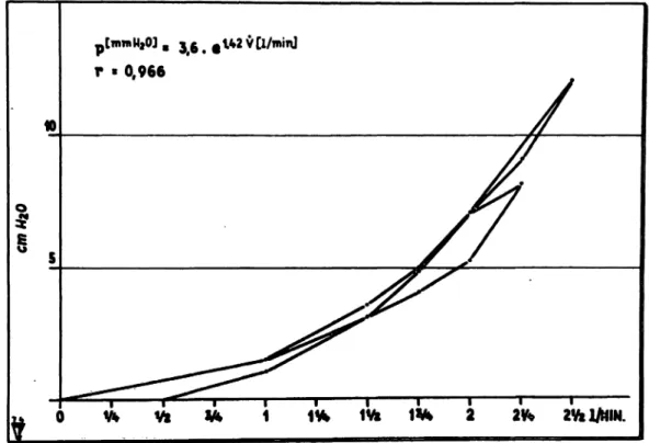
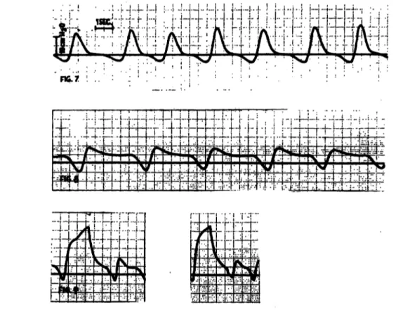
Fig. 6 shows the CPAP obtained ät various flow- rates tested in the anencephalic newborn. The results were reproducable. Fig? 7 depicts the pressure curve of the intubated baby's breathing cycle unassisted by any respiratory device, whereas Fig. 8 shows the CPAP curve using the apparatus
20
10
a -5 H
10 20
6 L/MIN.
^,—·» 3 L/MIN.
- 4 »»
9l
15* ^5° 90° 135° 175°
'•
Fig. 4. Positive pressure obtained in 3 mm tube with a canula of 0.9 mm at various angles and flow-iates.
Simbruner et al., Respirator with a new positive airway pressure device 189
Fig. 5. Time-pressure-curves obtained in a 3 mm tube at vaiious flow rates. Canula diameter 0.9 mm, parallel to the tube. X-axis: l cm = l sec. Y-axis: l mm = l cm water.
2 2fe 2W1/NIN.
0 Vt Vk W 1 1* IVi
Fig. 6. CPAP obtained in an anencephalic newborn at various flow-rates. 3 mm tube, 0.9 mm canula-diameter.
described. Pressure curves of sighing combined with CPAP are shown in Fig. 9. In this case sighing was achieved by means of the valve-mechanism.
The total airflow needed for it was approximately 2 litres to result in a positive pressure of 27 cm water.
5. Discussion
The respirator is considered to meet [a] all essential criteria for pediatric ventilatory assistance and [b]
offers some additional advantages. [a] Breathing
rates up to 100/min can be obtained. The infant can be sighed äs rarely äs once every 3 minutes.
Tidal volume can be regulated to äs little äs 5 ml and äs rmich äs 100ml. The inspiratory flow necessary for it lies between l -4 litres/min. The unit can be used to apply positive airway pressure.
The control modes depend on the fluidic circuits used. Our Controller allows controlled Ventilation in two modes, time cycled/pressure limited and pressure cycled/time limited. Any oxygen-mixer and humidifier can be integrated into the System, [b] This respirator is characterized by its miniature J. Perinat. Med. 4(1976)
Fig. 7. Time-pressure-curve during spontaneous Ventilation and Fig. 8. Time-pressure-curve during CPAP assisted Ventilation.
Fig. 9. Time-pressure-curve of sighing and CPAP in a closed systerh.
dimensions, versatility and its safe and simple construction. In addition there is no apparatus deadspace because the patient's expired air leaks out into the atmosphere directly at the end of the tracheal tube. This means rebreathing is completely prevented even if the tubings are disconnected.
Furthermore, the regulator and tubing supplying the air can be made disposable and therefore steril.
Miniature dimensions were made possible by use of fluidic elements for the Controller (10 X 10 X 5 cm) and a simply structured regulator (2 cm3).
Due to this fact the respirator is easily transportable and allows free access to the infant. Treatment of neonatal respiratory difficulties takes place in the labour ward, during transport and in the neonatal unit. As each location has its speciflc demands and facilities, adaptability isadventageous: in the labour ward the regulator supplied with oxygen by two flowmeters constitutes an always and immediately available CPAP- and mechanical Ventilation device with or without PEEP, if the pediatrician's thumb functions. äs a Controller. As soon äs the fluidic
Controller is available, the child is ready for trans- port to the neonatal unit, where heater, humidifler and oxygen-mixer are added for longterm Venti- lation. The pressüre-rise-velocity äs demonstrated in Fig. 5 meets the requirements for sighing in an open System. Because CPAP and sighing are achieved in an open System dangerous pressure can only be brought about if the flow-setting is gravely eraneous, but the blockage of an expira- tory limb, resulting in a steady pressure rise, carniot occur in this System. Thus in the applica- tion of CPAP and sighing the constant leakage offers maximum security and enables tracheal suction at any time. Except for two membrane valves the respirator contains no moving parts.
Only Information in form of pressure changes is fed into the fluidic circuits, the Output of which are again pressure changes. Therefore the only source of energy required for running the respirator is highly pressurized gas. This justifies an expec- tation of high technical reliability. At the present stage an adequate supply of gas for transportation
Simbruner et al., Respirator with a new positive airway pressure device 191 is endangered by the high gas consumption of the developing an integrated fluidic circuit for this fluidic circuits. This problem will be solved by particular application.
Summary
A simple and miniatme respirator was developed providing controlled Ventilation and application of a positive airway pressure. The positive airway pressure is achieved by an airflow through a canula into the airways. During expira- tion the direction of this insufflated air-flow is changed and the dynamic pressure necessary for it manifests itself äs a positive airway pressure. Mechanical Ventilation func- tions according to the principle of the Ayre-T-Piece: flow direction and, therefore Ventilation, is controlled by occlusion of the expiratory limb. Occlusion is brought about by inflating a balloon. The Inflation of the balloon is bontroDed by fluidic-circuits. They allow setting of frequency, duration of Inspiration and pressure limit. As the above mentioned System for creating a positive airway pressure is integrated, mechanical Ventilation with PEEP is achieved.
Tests on a lung model were performed to establish the variables which influence the amount of positive pressure produced by an air-flow through a canula into a tube.
Results indicate that the positive pressure obtained is in-
versely correlated to the diameter of tube and canula and varies with the angle of inflow (Tab. I, II, Fig. 4). The pressure-rise-velocity depicted in Fig. 5 suggests that sighing is possible in an open System. On an anencephalic newborn pressure-flow-ratios were established (Fig. 6).
Pressure-time curves during spontaneous breathing, CPAP assisted breathing and sighing combined with CPAP*
were recorded in a 3 month old baby (Fig. 7, 8,9).
The discussion states the technical performance of the respirator (frequency 100/min-l/3 min., tidal volume 5-100 ml, controlled Ventilation with pressure limitation, application of PEEP) and additional advantages (no apparatus deadspace, disposable i.e. sterile air supply- system, the miniature dimensions 10 X 10 X 5 cm, versatility and simple therefore technically reliable con- struction).
* Nowadays called IMV (Intermittant Mandatory Venti- lation)
Key-words: CPAP, fluidic Controller, IPPV, miniature respirator, respirator, transport.
Zusammenfassung
Ein Fluidik-kontrollierter Miniaturrespirator mit einer neuen Vorrichtung für positiven Atemwegsdruck
Wir entwickelten einen einfachen und kleinen Respirator, der kontrollierte Beatmung und die Anwendung eines po- sitiven Atemwegdruckes ermöglicht. Der positive Atem- wegsdruck wird mittels eines Luftstrahles, der aus einer Kanüle kommend in die Atemwege strömt, erzielt. Wäh- rend der Expiration wird die Richtung des Luftstromes geändert und der dafür notwendige dynamische Druck manifestiert sich als positiver Atemwegsdruck. Die mechanische Ventilation beruht auf dem Prinzip des Ayre- T-Rohres: die Strömungsrichtung des Atemgases und damit die Ventilation wird durch die Okklusion des ex- piratorischen Schenkels kontrolliert. Die Okklusion erfolgt durch das Aufblasen eines Ballones und wkd durch Fluidik-elemente gesteuert. Jene ermöglichen eine Ein- stellung der Frequenz, Inspirationsdauer und der Druck- grenze. Da die oben erwähnte Vorrichtung darin integriert ist, ist eine mechanische Beatmung mit PEEP. möglich.
An Hand eines Lungenmodelles wurde untersucht, welche Variablen die Höhe des positiven Druckes beeinflussen, der durch einen Luft ström aus einer Kanüle in einem
Tubus entsteht. Die Ergebnisse zeigen, daß der erzielte positive Druck eine negative Korrelation zum Durchmesser des Tubus und der Kanüle aufweist und mit dem Ein- strömwinkel variiert (Tab. I, II, Fig. 4). Die in Fig. 5 dar- gestellte Druckanstiegsgeschwindigkeit macht deutlich, daß eine Seufzeratmung in einem offenen System möglich ist. An einem anencephalen Neugeborenen wurde die Ab- hängigkeit des Druckes vom Flow untersucht (Fig. 6).
Druckzeitkurven wurden während Spontan und CPAP- assistierter Atmung und während kombinierter CPAP- Seufzeratmung* bei einem 3 monatigem Säugling aufge- zeichnet (Fig. 7,8,8). Die Diskussion befaßt sich mit dem technischen Vermögen des Respirators (Frequenz 100/min -1/3 min, Atemzugvolumen 5-100 nü, kontrollierte Be- atmung mit Druckbegrenzung, Anwendung von PEEP) und zusätzlichen Vorteilen (kein Geräte-Totraum, Ein- malgerät dh. steriles Luftzufuhrsystem, kleine Ausmaße, Vielseitigkeit und einfache, deshalb verläßliche Kon- struktion).
* In der Literatur derzeit als IMV (= Intermittant Manda- tory Ventilation) bezeichnet.
Schlüsselwörter: Fluidiksteuerung, Miniaturrespirator, positiver Atemwegsdruck (CPAP), positive Druckbeatmung, Transport.
J. Perinat. Med. 4 (1976)
Un respirateur de format tres reduit, a contröle liquide et dote d'un nouveau dispositif de pression positive de la voie aerienne
Un respirateur simple et de format tres reduit a ete mis au point pour assurer une Ventilation contrölee et une pression positive de la voie aerienne. Cette pression est fournie par un flux d'air ä travers une canule dans les voies aeriennes La direction de ce flux d'air insuffle est modifiee durant Fexpiration et la pression dynamique que cela necessite se manifeste comme etant une pression positive de la voie aerienne. La Ventilation mecanique fonctionne selon le principe du Ayre-T-Piece: la direction du flux et, par suite, la Ventilation sont controlees par l'occlusion du membre expiratoire. L'occlusion est provoquee par le gonflement d'un ballon contröle par des circuits liquides qui permettent d'etablir la frequence, la duree del'inspir- ation et la limite de pression. L'integration du Systeme mentionne ci-dessus et createur d'une pression positive de la voie aerienne assure une Ventilation mecanique avec PEEP (positive end expiratory pressure).
Des tests sur un modele pulmonaire ont ete effectues afin d'etablir les variables qui influencent la mesure de pression
positive produite par un flux d'air a travers une canule jusque dans un tube. Les resultats indiquent que la pression positive obtenue est inversement proportionelle au diametre du tube et de la canule et qu'elle varie avec Tangle de l'influx (Tab. I, II, Fig. 4). La rapidite de la Hausse de pression representee a la Fig. 5 semble prouver que le soupk est possible dans un Systeme ouvert. Des rapports proportionnels de flux de pression ont ete etablis sur un nouveau-ne anencephale (Fig. 6) On a egalement enregistre chez un bebe de 3 mois des courbes de temps de pression pendant la respiration spontanee, la respiration soutenue par la CPAP (pression positive continue de la voie aerienne) et le spupir combine avec la CPAP (Fig. 7, 8, 9).
La discussion amene a constater la performance technique du respirateur (frequence 100/min-l/3 min., volume de flux 5-100 ml, Ventilation contrölee avec limitation de pression, application du PEEP) et les avantages additionnels (appareil sans espace mort, Systeme d'äpport d'air disponible, c.a.d. sterile, dimensions reduites 10 X 10 X 5 cm, versatilite et construction simple, donc d'une tech- nique süre).
Mots-cles: contröleur liquide, CPAP, IPPV, respirateur, respirateur miniäture, transport.
Bibliography
[1] GREGORY, G. A., L A. KITTERMAN, R. H. PHIBBS, W. H. TOOLEY, W. K. HAMILTON: Treatment of the idiopathic respiratory-distress syndrome with continuous positive airway pressure, New Engl J.
Med. 284(1971)1333
[2] SUGERMAN, H. J., R. M. ROGERS, L. D. MILLER:
Positive end-expiratory pressure (PEEP); indications and physiologic considerations, Chest. 62 (1972) Suppl. (Part 2)
13) BAUM, J. D., N. R. C. ROBERTON: Distending pressure in infants with respiratory distress syndrome.
Archives of Diseases in Chüdhood 49 (1974) 771 [4] CUMARASAMY, N., R. NÜSSLI, D. VISHER,
P. H. DANGEL, G. V. DUC: Artificial ventüation in hyaline membrane disease: the use pf positive end- expiratory pressure and continuous positive airway pressure.
Pediatrics 51 (1973) 629
[5] HALLER, J. A., JR., J.S.DONAHQO, J. J.WHITHE, P. C. MOYNIHAN, A. G. GALVIS: Use of Continuous Positive Airway Pressure in the Improved Post- operative Management of Neonatal Respiratory Emergencies. Annals pf thoracic Surgery 15 (1973) [6]PFITZNER, J., M. A. BRANTHWAITE, I. C. W.607 ENGLISCH, E. A. SHINEBOURNE: Continuous positive airway pressure. A new System.
Anaesthesia29(1974)320
[7] NOVOGRODER, M., N. MAX KUANYING, A. I.
EIDELMAN, L. M. GÄRTNER: Nasopharyngeal Ventilation in respiratory distress syndrome.
J. Pediatrics 8 (1973) 1059
[8] RHODES, P. G., R. T. HALL: Continuous positive airway pressure delivered by face mask in infants with idiopathic respiratory distress syndrome: a con- trolled study.
Pediatrics 52 (1973) 17
[9] LOUGH, M. D.: Meehanical Ventilation. In: Pediatric Respiratory Therapy. Year Book Medical Publishers, Inc. Chicago, 1974
[10JLEMBURG, P.: Zur Technik der künstlichen Beat- mung beim Neugeborenen und Säugling.
Medizinische Technik 6 (1972) 267
[11] ARklNSTALL, W. W., S. W. EPSTEIN: Meehanical Failure of a Ventilator: A Case Report.
Anesthesia and Analgesia 52 (1973) 48
[12] SMITH, R. K.: Respiratory care applications for fluidics.
Respiratory Therapy 3 (1973) 29
[13] EDITORIALS: The Difference Between PEEP, CPPB and CPAP.
Respiratory Care 19 (1974) 14 ^}
Received February 10, 1975. Accepted 'September 12, 1975.
Dr. G. Simbruner
Department für Neonatologie und angeborene Störungen, Univ.-Kinderklinik
A-1090 Wien, Lazarettgasse 14