A Systems-Theoretic Approach to Safety in Software-Intensive Systems
Nancy G. Leveson
Abstract: Traditional accident models were devised to explain losses caused by failures of physical devices in relatively simple systems. They are less useful for explaining accidents in software-intensive systems and for non-technical aspects of safety such as organizational culture and human decision-making. This paper describes how systems theory can be used to form new accident models that better explain system accidents (accidents arising from the interactions among components rather than individual component failure), software-related accidents, and the role of human decision-making. Such models consider the social and technical aspects of systems as one integrated process and may be useful for other emergent system properties such as security. The loss of a Milstar satellite being launched by a Titan/Centaur launch vehicle is used as an illustration of the approach.
Keywords: software safety, system safety, accident models, software engineering
1 Introduction
All attempts to engineer safer systems rest upon underlying causal models of how accidents occur, although engineers may not be consciously aware of their use of such a model. An underlying assumption of these accident models is that there are common patterns in accidents and that accidents are not simply random events. By defining those assumed patterns, accident models may act as a filter and bias toward considering only certain events and conditions or they may expand consideration of factors often omitted. The completeness and accuracy of the model for the type of system being considered will be critical in how effective are the engineering approaches based on it.
At the foundation of almost all causal analysis for engineered systems today is a model of accidents that assumes they result from a chain (or tree) of failure events and human errors.
The causal relationships between the events are direct and linear, representing the notion that the preceding event or condition must have been present for the subsequent event to occur, i.e., if event X had not occurred, then the following event Y would not have occurred. As such, event chain models encourage limited notions of linear causality, and they cannot account for indirect and non-linear relationships.
The selection of events to include in an event chain is dependent on the stopping rule used
to determine how far back the sequence of explanatory events goes. Although it is common
to isolate one or more events or conditions (usually at the beginning of chain) and call them
the cause or the proximate, direct or root cause of an accident or incident and to label the
other events or conditions as contributory, there is no basis for this distinction. Usually a root
cause selected from the chain of events has one or more of the following characteristics: (1) it
represents a type of event that is familiar and thus easily acceptable as an explanation for the
accident; (2) it is a deviation from a standard; (3) it is the first event in the backward chain for which a “cure” is known 1 ; and (4) it is politically acceptable as the identified cause. The backward chaining may also stop because the causal path disappears due to lack of information.
Rasmussen suggests that a practical explanation for why actions by operators actively involved in the dynamic flow of events are so often identified as the cause of an accident (and operator actions are often selected as the stopping point in an accident event chain) is the difficulty in continuing the backtracking “through” a human [24]. Identifying accident causes in this way can be a hindrance in learning from and preventing future accidents.
As just one example, the accident report on a friendly fire shootdown of a helicopter over the Iraqi No-Fly-Zone in 1994 describes the accident as a chain of events leading to the shootdown [27]. Included in the chain of events provided is the fact that the helicopter pilots did not change to the radio frequency required in the No-Fly-Zone when they entered it (they stayed on the enroute frequency). Stopping at this event in the chain, it appears that the helicopter pilots were at least partially at fault for the loss by making an important mistake. An independent account of the accident [20], however, notes that the U.S. Commander of the operation had made an exception about the radio frequency to be used by the helicopters in order to mitigate a different safety concern, and therefore the pilots were simply following orders. This commanded exception to radio procedures is not included in the chain of events included in the official government accident report, but it provides a very different understanding of the role of the helicopter pilots in the loss.
There are two basic reasons for conducting an accident investigation: (1) to assign blame for the accident and (2) to understand why it happened so that future accidents can be prevented.
When the goal is to assign blame, the backward chain of events considered often stops when someone or something appropriate to blame is found. As a result, the selected initiating event may provide too superficial an explanation of why the accident occurred to prevent similar losses in the future. For example, stopping at the O-ring failure in the Challenger accident and fixing that particular design flaw would not have eliminated the systemic flaws that could lead to accidents in the future. For Challenger, examples of those systemic problems include flawed decision making and the pressures that led to it, poor problem reporting, lack of trend analysis, a “silent” or ineffective safety program, communication problems, etc. None of these are “events” (although they may be manifested in particular events) and thus do not appear in the chain of events leading to the accident. Wisely, the authors of the Challenger accident report used an event chain only to identify the proximate physical cause and not the reasons those events occurred, and the report writers’ recommendations led to many important changes at NASA or at least attempts to make such changes [26]. 2
Blame is not an engineering concept; it is a legal or moral one. Usually there is no objective criterion for distinguishing one factor or several factors from other factors that contribute to an accident. While lawyers and insurers recognize that many factors contribute to a loss event, for practical reasons and particularly for establishing liability, they often oversimplify the causes of accidents and identify what they call the proximate (immediate or direct) cause. The goal is to determine the parties in a dispute that have the legal liability to pay damages, which may be
1
As an example, a NASA Procedures and Guidelines Document (NPG 8621 Draft 1) defined a root cause as:
“Along a chain of events leading to a mishap, the first causal action or failure to act that could have been controlled systematically either by policy/practice/procedure or individual adherence to policy/practice/procedure.”
2
Recently, another Space Shuttle has been lost. While the proximate cause for the Columbia accident (foam
hitting the wing of the orbiter) was very different than for Challenger, many of the systemic or root causes were
similar and reflected either inadequate fixes of these factors after the Challenger accident or their re-emergence
in the years between these losses [7].
affected by the ability to pay or by public policy considerations, such as discouraging company management or even an entire industry from acting in a particular way in the future.
When learning how to engineer safer systems is the goal rather than identifying who to punish and establishing liability, then the emphasis in accident analysis needs to shift from cause (in terms of events or errors), which has a limiting, blame orientation, to understanding accidents in terms of reasons, i.e., why the events and errors occurred. In an analysis by the author of recent aerospace accidents involving software in some way, most of the reports stopped after assigning blame—usually to the operators who interacted with the software—and never got to the root of why the accident occurred, e.g., why the operators made the errors they did and how to prevent such errors in the future (perhaps by changing the software) or why the software requirements specified unsafe behavior and why that error was introduced and why it was not detected and fixed before the software was used [12].
While attempts have been made to extend traditional safety engineering techniques such as fault tree analysis and probabilistic risk assessment, based on event-chain models of accidents to software-intensive systems, the results have not been terribly successful. Perhaps the lack of significant progress in dealing with software in safety-critical systems is the result of inappro- priately attempting to extend the techniques that were successful in simpler, electromechanical systems and were based on models of accident causation that no longer apply.
Accidents can be separated into two types: those caused by failures of individual components and those caused by dysfunctional interactions between non-failed components. The dysfunc- tional behavior in modern, high-tech systems is often commanded by software, such as the command by the Mars Polar Lander descent control software to shut off the descent engines pre- maturely while still 40 meters above the Martian surface. In this and in most software-related accidents, the software operates exactly as specified, that is, the software, following its require- ments, commands component behavior that violates system safety constraints or the software design contributes to unsafe behavior by human operators. As such, the traditional event-chain model, with its emphasis on component failure, is inappropriate for today’s software-intensive, complex human-machine systems with distributed decision-making across both physical and organizational boundaries.
The basic premise of this paper is that to make significant progress in dealing with safety in complex systems, we need new models and conceptions of how accidents occur that more accurately and completely reflect the types of accidents we are experiencing today. Simply building more tools based on the current chain-of-events model will not result in significant gains. This paper presents one example of such a model, but others are possible.
The new model, called STAMP (Systems-Theoretic Accident Model and Processes), uses a systems-theoretic approach to understanding accident causation. Systems theory allows more complex relationships between events to be considered (e.g., feedback and other indirect rela- tionships) and also provides a way to look more deeply at why the events occurred. Accident models based on systems theory consider accidents as arising from the interactions among system components and usually do not specify single causal variables or factors [9]. Whereas industrial (occupational) safety models focus on unsafe acts or conditions and reliability engineering em- phasizes failure events and the direct relationships between these events, a systems approach to safety takes a broader view by focusing on what was wrong with the system’s design or opera- tions that allowed the accident to take place. The proximal events that precede an accident are simply symptoms of a lack of enforcement of safety in the design and operation of the system:
to prevent accidents we need to go beyond the events to understand why those events occurred, i.e., the larger system and process producing the events.
The next section provides some basic background on system theory, followed by a description
of a systems-theoretic approach to safety. The basic concepts are illustrated using the loss of a Milstar satellite.
1.1 Safety as an Emergent System Property
Event chain models rest on traditional analytic reduction: Physical systems are decomposed into separate physical components so the parts can be examined separately, and behavior is decom- posed into events over time. This decomposition assumes that such separation is feasible: that is, each component or subsystem operates independently and analysis results are not distorted when the components are considered separately. This assumption in turn implies (1) that the components or events are not subject to feedback loops and non-linear interactions and (2) that the behavior of the components is the same when examined alone as when they are playing their part in the whole. A third fundamental assumption is that the principles governing the assembly of the components into the whole are straightforward, that is, the interactions among the subsystems are simple enough that they can be considered separate from the behavior of the subsystems themselves [28].
These assumptions are reasonable for many properties and systems, but they start to fall apart in complex systems. Systems theory dates from the thirties and forties and was a response to limitations of the classic analysis techniques in coping with the increasingly complex systems being built [4]. Norbert Weiner applied the approach to control and communications engineering [29] while Ludwig von Bertalanffy developed similar ideas for biology [3]. It was Bertalanffy who suggested that the emerging ideas in various fields could be combined into a general theory of systems.
The systems approach focuses on systems taken as a whole, not on the parts examined separately. It assumes that some properties of systems can only be treated adequately in their entirety, taking into account all facets relating the social to the technical aspects [4]. These system properties derive from the relationships between the parts of systems: how the parts interact and fit together [1]. Thus the systems approach concentrates on the analysis and design of the system as a whole as distinct from the components or the parts. While components may be constructed in a modular fashion, the original analysis and decomposition must be performed top down.
The foundation of systems theory rests on two pairs of ideas: (1) emergence and hierarchy and (2) communication and control [4].
1.1.1 Emergence and Hierarchy
The first pair of basic system theory ideas are emergence and hierarchy. A general model of complex systems can be expressed in terms of a hierarchy of levels of organization, each more complex than the one below, where a level is characterized by having emergent properties. Emer- gent properties do not exist at lower levels; they are meaningless in the language appropriate to those levels. The shape of an apple, although eventually explainable in terms of the cells of the apple, has no meaning at that lower level of description. Thus, the operation of the processes at the lower levels of the hierarchy result in a higher level of complexity—that of the whole apple itself—that has emergent properties, one of them being the apple’s shape. The concept of emergence is the idea that at a given level of complexity, some properties characteristic of that level (emergent at that level) are irreducible.
Safety is an emergent property of systems. Determining whether a plant is acceptably safe
is not possible by examining a single valve in the plant. In fact, statements about the “safety of
the valve” without information about the context in which that valve is used, are meaningless.
Conclusions can be reached, however, about the reliability of the valve, where reliability is defined as “the ability of a system or component to perform its required functions under stated conditions for a specified period of time” [8], i.e., that the behavior of the valve will satisfy its specification over time and under given conditions. This is one of the basic distinctions between safety and reliability: Safety can only be determined by the relationship between the valve and the other plant components—that is, in the context of the whole. Therefore it is not possible to take a single system component, like a software module, in isolation and assess its safety. A component that is perfectly safe in one system may not be when used in another. Attempts to assign safety levels to software components in isolation from a particular use, as is currently the approach in some international safety standards, is misguided.
Event-based models of accidents, with their relatively simple cause-effect links, were cre- ated in an era of mechanical systems and then adapted for electro-mechanical systems. The use of software in engineered systems has removed many of the physical constraints that limit complexity and has allowed engineers to incorporate greatly increased complexity and coupling in systems containing large numbers of dynamically interacting components. In the simpler systems of the past, where all the interactions between components could be predicted and handled, component failure was the primary cause of accidents. In today’s complex systems, made possible by the use of software, this is no longer the case. The same applies to security and other system properties: While some vulnerabilities may be related to a single component only, a more interesting class of vulnerability emerges in the interactions among multiple system components. Vulnerabilities of this type are system vulnerabilities and are much more difficult to locate and predict.
A second basic part of systems theory, hierarchy theory, deals with the fundamental dif- ferences between levels of a hierarchy. Its ultimate aim is to explain the relationships between different levels: what generates the levels, what separates them, and what links them. Emergent properties associated with a set of components at one level in a hierarchy are related to con- straints upon the degree of freedom of those components. In a systems-theoretic view of safety, the emergent safety properties are controlled or enforced by a set of safety constraints related to the behavior of the system components. Safety constraints specify those relationships among system variables or components that constitute the non-hazardous or safe system states—for example, the power must never be on when the access door to the high-voltage power source is open; pilots in a combat zone must always be able to identify potential targets as hostile or friendly; the public health system must prevent the exposure of the public to contaminated water; and the spacecraft lander software must control the rate of descent of the spacecraft to the planet’s surface. Accidents result from interactions among system components that violate these constraints—in other words, from a lack of appropriate constraints on system behavior.
1.1.2 Communication and Control
The second pair of basic systems theory ideas is communication and control. Regulatory or control action is the imposition of constraints upon the activity at one level of a hierarchy, which define the “laws of behavior” at that level yielding activity meaningful at a higher level.
Hierarchies are characterized by control processes operating at the interfaces between levels.
Checkland writes:
Control is always associated with the imposition of constraints, and an account of a
control process necessarily requires our taking into account at least two hierarchical
levels. At a given level, it is often possible to describe the level by writing dynamical equations, on the assumption that one particle is representative of the collection and that the forces at other levels do not interfere. But any description of a control process entails an upper level imposing constraints upon the lower. The upper level is a source of an alternative (simpler) description of the lower level in terms of specific functions that are emergent as a result of the imposition of constraints [4, p.87].
Control in open systems (those that have inputs and outputs from their environment) im- plies the need for communication. Bertalanffy distinguished between closed systems, in which unchanging components settle into a state of equilibrium, and open systems, which can be thrown out of equilibrium by exchanges with their environment [3]. The notions of time lag, noise, and bandwidth play important roles in communication between hierarchical control levels.
In systems theory, open systems are viewed as interrelated components that are kept in a state of dynamic equilibrium by feedback loops of information and control. A system is not treated as a static design, but as a dynamic process that is continually adapting to achieve its ends and to react to changes in itself and its environment. To be safe, the original design must not only enforce appropriate constraints on behavior to ensure safe operation (the enforcement of the safety constraints), but it must continue to operate safely as changes and adaptations occur over time [30].
1.2 Systems-Theoretic Approaches to Safety
In response to the limitations of event-chain models, systems theory has been proposed as a way to understand accident causation (see, for example, [22, 11]). When using a systems-theoretic accident model, accidents are viewed as the result of flawed processes involving interactions among system components, including people, societal and organizational structures, engineering activities, and the physical system.
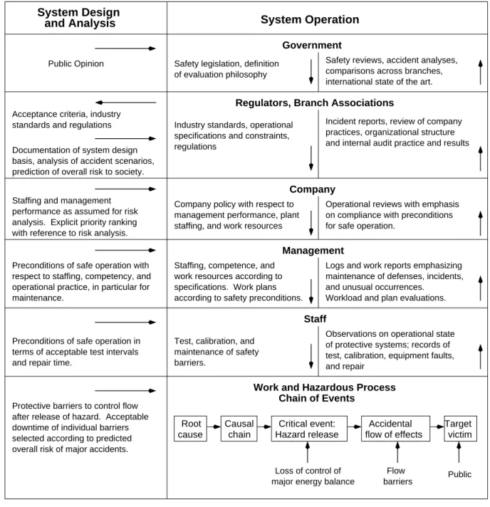
Rasmussen and Svedung [22, 23] have added some features of system theory into the classic event-chain model by adding hierarchical control levels—representing government, regulators and associations, company, management, and staff—above the event chain (Figure 1). Informa- tion flow is mapped at all levels and between levels. The model concentrates on the operation of the socio-technical system: information from the system design and analysis process (the left column in the figure) is treated as input to the operations process (the right column). At each level, they model the factors involved using event chains, with links to the chain at the level below. Unfortunately, retaining event chains and event decomposition at the hierarchical levels limits the benefits that can be obtained by taking a systems approach.
Leveson has defined another accident model, called STAMP (Systems-Theoretic Accident Modeling and Processes) based on systems theory [11]. In STAMP, accidents are conceived as resulting not from component failures, but from inadequate control or enforcement of safety- related constraints on the design, development, and operation of the system. In the Space Shuttle Challenger accident, for example, the O-rings did not adequately control propellant gas release by sealing a tiny gap in the field joint. In the Mars Polar Lander loss, the software did not adequately control the descent speed of the spacecraft—it misinterpreted noise from a Hall effect sensor as an indication the spacecraft had reached the surface of the planet.
Accidents such as these, involving engineering design errors, may in turn stem from in-
adequate control over the development process, i.e., risk is not adequately managed (through
communication and feedback) in the design, implementation, and manufacturing processes. Con-
trol is also imposed by the management functions in an organization—the Challenger accident
Protective barriers to control flow after release of hazard. Acceptable downtime of individual barriers selected according to predicted overall risk of major accidents.
Critical event:
Hazard release cause
Root Causal
chain flow of effects
Accidental Target victim
Public barriers
Flow Loss of control of
major energy balance Government of evaluation philosophy
Staffing and management performance as assumed for risk analysis. Explicit priority ranking with reference to risk analysis.
Safety reviews, accident analyses, comparisons across branches, international state of the art.
Regulators, Branch Associations
Industry standards, operational Incident reports, review of company practices, organizational structure and internal audit practice and results Acceptance criteria, industry
standards and regulations Documentation of system design basis, analysis of accident scenarios, prediction of overall risk to society.
System Operation System Design
and Analysis
Company
Operational reviews with emphasis on compliance with preconditions for safe operation.
staffing, and work resources management performance, plant Company policy with respect to
Management
Workload and plan evaluations.
and unusual occurrences.
maintenance of defenses, incidents, Logs and work reports emphasizing
according to safety preconditions.
specifications. Work plans work resources according to Staffing, competence, and
maintenance.
operational practice, in particular for respect to staffing, competency, and Preconditions of safe operation with
Staff
and repair
test, calibration, equipment faults, of protective systems; records of Observations on operational state barriers.
maintenance of safety Test, calibration, and and repair time.
terms of acceptable test intervals Preconditions of safe operation in
Safety legislation, definition Public Opinion
specifications and constraints, regulations
Work and Hazardous Process Chain of Events
Figure 1: Rasmussen-Svedung Model
involved inadequate controls in the launch-decision process, for example—and by the social and political system within which the organization exists.
STAMP is constructed from three basic concepts: constraints, hierarchical levels of control, and process models. These concepts, in turn, give rise to a classification of control flaws that can lead to accidents. Each of these is described below.
1.2.1 Constraints
The most basic concept in STAMP is not an event, but a constraint. In systems theory or control theory, systems are viewed as hierarchical structures where each level imposes constraints on the activity of the level beneath it—that is, constraints or lack of constraints at a higher level allow or control lower-level behavior [4]. Safety-related constraints specify those relationships among system variables that constitute the nonhazardous or safe system states.
Instead of viewing accidents as the result of an initiating (root cause) event in a chain of events leading to a loss (which must somehow be broken in order to prevent them), accidents are viewed as resulting from interactions among components that violate the system safety constraints. The control processes that enforce these constraints must limit system behavior to the safe changes and adaptations implied by the constraints.
Note that accidents caused by basic component failures are included in this model, as well as those caused by interactions among components. Identifying the failure events themselves, how- ever, does not provide enough information about why they occurred to prevent similar accidents in the future. Component failures may result from inadequate constraints on the manufac- turing process; inadequate engineering design such as missing or incorrectly implemented fault tolerance; lack of correspondence between individual component capacity (including humans) and task requirements; unhandled environmental disturbances (e.g., electromagnetic inteference or EMI); inadequate maintenance, including preventive maintenance; physical degradation over time (wearout); etc. Control therefore need not be imposed by a physical “controller” but may be controlled through system design or manufacturing processes and procedures. Systems-theoretic accident models go beyond simply blaming component failure for accidents (and perhaps then adding redundancy to the design to handle them) and require that the reasons be identified for why those failures occur and lead to accidents.
1.2.2 Hierarchical Levels of Control
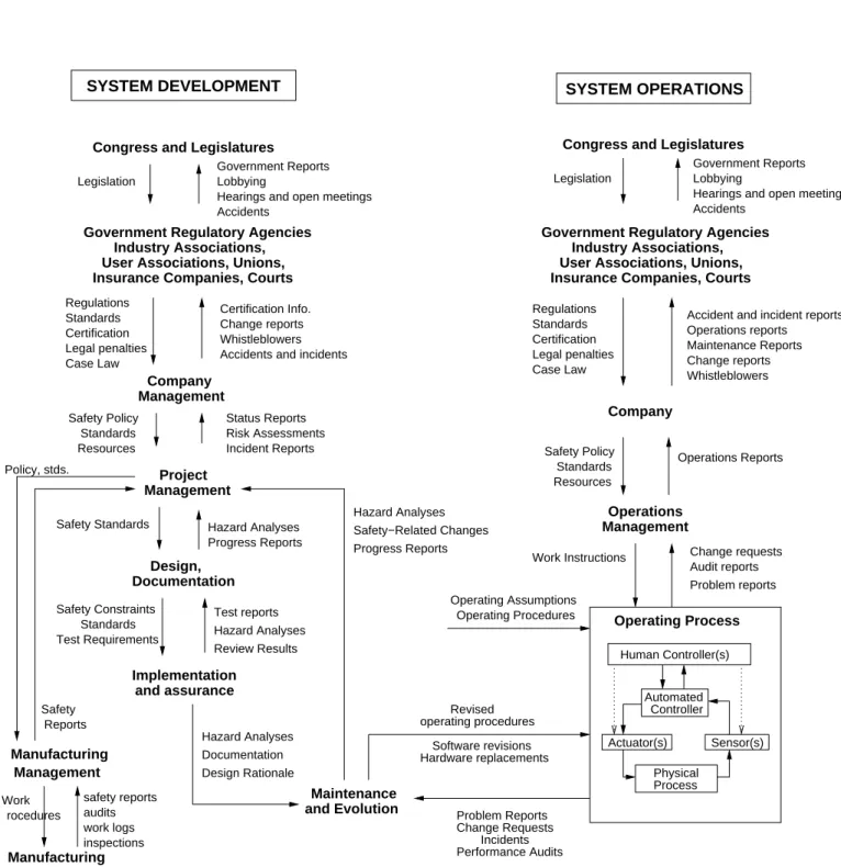
The second concept in STAMP (and a basic concept in systems theory) is hierachical levels of control. Figure 2 shows a generic hierarchical safety control model. Accidents result from inadequate enforcement of constraints on behavior (e.g., the physical system, engineering design, management, and regulatory behavior) at each level of the socio-technical system.
The model in Figure 2 has two basic hierarchical control structures—one for system devel- opment (on the left) and one for system operation (on the right)—with interactions between them. An aircraft manufacturer, for example, might only have system development under its immediate control, but safety involves both development and operational use of the aircraft, and neither can be accomplished successfully in isolation: Safety must be designed into the system, and safety during operation depends partly on the original design and partly on effective con- trol over operations and the changes and adaptations in the system over time. Manufacturers must communicate to their customers the assumptions about the operational environment upon which the safety analysis was based, as well as information about safe operating procedures.
The operational environment, in turn, provides feedback to the manufacturer about the perfor-
Maintenance Congress and Legislatures
Legislation
Company
Congress and Legislatures Legislation
Legal penalties Certification Standards Regulations Government Reports
Lobbying
Hearings and open meetings Accidents
Case Law Legal penalties Certification Standards
Problem reports Incident Reports
Risk Assessments
Safety−Related Changes
Test reports Test Requirements
Standards
Review Results Safety Constraints
Implementation
Hazard Analyses Progress Reports Safety Standards Hazard Analyses
Progress Reports
Design, Work Instructions Change requests
Audit reports Regulations
Industry Associations, Government Regulatory Agencies
Management
Management Project
Government Regulatory Agencies User Associations, Unions,
Documentation
and assurance
and Evolution
SYSTEM OPERATIONS
Insurance Companies, Courts
Physical Actuator(s) Industry Associations,
Performance Audits Incidents Change Requests
User Associations, Unions,
Accidents and incidents
Government Reports Lobbying
Hearings and open meetings Accidents
Whistleblowers Change reports Maintenance Reports Operations reports
Accident and incident reports
Problem Reports Hardware replacements
Software revisions
Hazard Analyses Operating Process
Case Law
SYSTEM DEVELOPMENT
Insurance Companies, Courts
Status Reports
Operating Assumptions Operating Procedures
Revised operating procedures Whistleblowers
Change reports Certification Info.
rocedures
safety reports work logs Manufacturing
inspections
Hazard Analyses Documentation Design Rationale
Company
Resources Standards
Safety Policy Operations Reports
Management Operations Resources
Standards Safety Policy
audits Work
Policy, stds.
Reports Safety
Management
Manufacturing Sensor(s)
Human Controller(s)
Process Automated
Controller
Figure 2: General Form of a Model of Socio-Technical Control.
mance of the system during operations. Although difficult to show without excessively cluttering the figure, interaction may occur at all levels between the development and operations control structures.
Between the hierarchical levels of each control structure, effective communication channels are needed, both a downward reference channel providing the information necessary to impose constraints on the level below and a measuring channel to provide feedback about how effectively the constraints were enforced. For example, company management in the development process structure may provide a safety policy, standards, and resources to project management and in return receive status reports, risk assessment, and incident reports as feedback about the status of the project with respect to the safety constraints. As described later, time lag, noise, and bandwidth must be considered when analyzing the performance of the communication channels.
The safety control structure often changes over time, which accounts for the observation that accidents in complex systems frequently involve a migration of the system toward a state where a small deviation (in the physical system or in human operator behavior) can lead to a catastrophe. The foundation for an accident is often laid years before [25]: One event may trigger the loss, but if that event had not happened, another one would have. Union Carbide and the Indian government blamed the Bhopal MIC (methyl isocyanate) release (among the worst industrial accidents in history) on human error—the improper cleaning of a pipe at the chemical plant. However, the maintenance worker was, in fact, only a minor and somewhat irrelevant player in the loss [10]. Instead, degradation in the safety margin occurred over time and without any particular single decision to do so but simply as a series of decisions that moved the plant slowly toward a situation where any slight error would lead to a major accident:
The stage for an accidental course of events very likely is prepared through time by the normal efforts of many actors in their respective daily work context, responding to the standing request to be more productive and less costly. Ultimately, a quite normal variation in somebody’s behavior can then release an accident. Had this
‘root cause’ been avoided by some additional safety measure, the accident would very likely be released by another cause at another point in time. In other words, an explanation of the accident in terms of events, acts, and errors is not very useful for design of improved systems [24].
Degradation of the safety-control structure over time may be related to asynchronous evo- lution [9], where one part of a system changes without the related necessary changes in other parts. Changes to subsystems may be carefully designed, but consideration of their effects on other parts of the system, including the control aspects, may be neglected or inadequate. Asyn- chronous evolution may also occur when one part of a properly designed system deteriorates. In both these cases, the erroneous expectations of users or system components about the behavior of the changed or degraded subsystem may lead to accidents. The Ariane 5 trajectory changed from that of the Ariane 4, but the inertial reference system software did not [15]. One factor in the loss of contact with the SOHO (SOlar Heliospheric Observatory) spacecraft in 1998 was the failure to communicate to operators that a functional change had been made in a software procedure to perform gyro spin-down [17].
For an accident model to handle system adaptation over time, it must consider the processes
involved in accidents and not simply events and conditions: Processes control a sequence of
events and describe system and human behavior as it changes and adapts over time rather than
considering individual events and human actions.
Model of Interfaces Model of
Process
Model of Automation Human Supervisor
Model of Interfaces
Process
outputs Process
inputs Disturbances
Process Controlled Automated Controller
Actuators Sensors
Measured variables Model of
Process
Controlled variables
Controls Displays
(Controller)
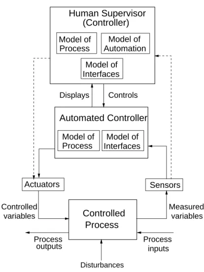
Figure 3: A standard hierarchical three-level control loop.
1.2.3 Process Models
Besides constraints and hierarchical levels of control, a third basic concept in STAMP is that of process models. Figure 3 shows a typical process-control loop with an automated controller supervised by a human controller. Any controller—human or automated—needs a model of the process being controlled to effectively control it. The model may contain only one or two state variables, such as the model required for a simple thermostat, which contains the current temperature and the desired setpoint, or it may be very complex, such as the model of the airspace required for air traffic control. Human controllers of automated systems must have an additional model of the automation as well as the controlled process, and both the human controller and the software need models of the interfaces between system components.
Whether the model is embedded in the control logic of an automated controller or in the mental model of a human controller, it must contain the same type of information: the required relationship among the system variables (the control laws), the current state (the current values of the system variables), and the ways the process can change state. This model is used to determine what control actions are needed, and it is updated through various forms of feedback.
A model of the controlled process is required at all levels of the hierarchical control structure.
There may, of course, be multiple human and automated controllers in the control loop, and computers may play roles other than as a direct controller. For example, computers may act as automated decision aids that provide information to the human controller but do not directly issue control commands. If the computer provides decision aiding, then the software must still contain a model of the process because it is indirectly controlling the process.
Time is an important consideration; control actions will, in general, lag in their effects on the process because of delays in signal propagation around the control loop: an actuator may not respond immediately to an external command signal; the process may have delays in responding to manipulated variables; and the sensors may obtain values only a certain sampling intervals.
Time lags restrict the speed and extent with which the effects of disturbances, both within the process itself and externally derived, can be reduced. They also impose extra requirements on the controller, for example, the need to infer delays that are not directly observable. Accidents can occur due to inadequate handling of these delays. Noise and bandwidth can similarly impact performance of the control loop.
1.2.4 A Classification of Control Flaws Leading to Accidents
In basic systems theory, to effect control over a system requires four conditions [2, 5]:
• Goal Condition: The controller must have a goal or goals, e.g., to maintain the setpoint or to maintain the safety constraints.
• Action Condition: The controller must be able to affect the state of the system in order to keep the process operating within predefined limits or safety constraints despite internal or external disturbances. Where there are multiple controllers and decision makers, the actions must be coordinated to achieve the goal condition. Uncoordinated actions are particularly likely to lead to accidents in the boundary areas between controlled processes or when multiple controllers have overlapping control responsibilities.
• Model Condition: The controller must be (or contain) a model of the system, as de- scribed above. Accidents in complex systems frequently result from inconsistencies between the model of the process used by the controllers (both human and software) and the actual process state; for example, the software thinks the plane is climbing when it is actually descending and as a result applies the wrong control law or the pilot thinks a friendly aircraft is hostile and shoots a missile at it.
• Observability Condition: The controller must be able to ascertain the state of the system from information about the process state provided by feedback. Feedback is used to update and maintain the process model used by the controller.
Using systems theory, accidents can be understood in terms of failure to adequately satisfy these four conditions:
1. Hazards and the safety constraints to prevent them are not identified and provided to the controllers (goal condition);
2. The controllers are not able to effectively maintain the safety constraints or they do not
make appropriate or effective control actions for some reason, perhaps because of inade-
quate coordination among multiple controllers (action condition);
(boundary and overlap areas)
Inadequate coordination among controllers and decision−makers
Communication flaw
Inadequate Execution of Control Action
Inadequate or missing feedback
Communication flaw Time lag
Inadequate sensor operation (incorrect or no information provided) Inadequate actuator operation
Time lag
Not provided in system design
Design of control algorithm (process) does not enforce constraints Inappropriate, ineffective, or missing control actions for identified hazards
Time lags and measurement inaccuracies not accounted for Flaw(s) in creation process
Flaws(s) in updating process (asynchronous evolution)
Process models inconsistent, incomplete, or incorrect (lack of linkup) Inadequate control actions (enforcement of constraints)
Control Flaws Leading to Hazards
Unidentified hazards
Figure 4: A classification of control flaws leading to accidents.
3. The process models used by the software or by human controllers (usually called mental models in the case of humans) become inconsistent with the process and with each other (model condition); and
4. The controller is unable to ascertain the state of the system and update the process models because feedback is missing or inadequate (observability condition).
When using a systems-theoretic accident model such as STAMP, the control flaws identified above are mapped to the components of the control loop and used in understanding and pre- venting accidents. Figure 4 shows a categorization of control flaws that can lead to the violation of the four conditions above. This categorization can be used in the creation of new hazard and accident analysis techniques (see, for example, [14, 6]).
2 Using a Systems-Theoretic Accident Model
The rest of this paper contains an extensive example that uses STAMP to understand the
reasons for a software-related accident. On April 30, 1999, at 12:30 EDT, a Titan IV B-32
booster equipped with a Centaur TC-14 upper stage was launched from Cape Canaveral. The
mission was to place a Milstar-3 satellite into geosynchronous orbit. Milstar is a joint services
satellite communications system that provides secure, jam resistant, worldwide communications
to meet wartime requirements. It was the most advanced military communications satellite
system to that date. The first Milstar satellite was launched February 7, 1994 and the second
was launched November 5, 1995. This mission was to be the third launch.
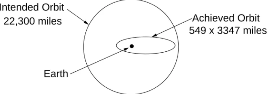
As a result of some anomalous events, the Milstar satellite was placed in an incorrect and unusable low elliptical final orbit, as opposed to the intended geosynchronous orbit. This accident is believed to be one of the most costly unmanned losses in the history of Cape Canaveral launch operations. The Milstar satellite cost about $800 million and the launcher an additional $433 million.
To their credit, the accident investigation board went beyond the usual chain-of-events model and instead interpreted the accident in terms of a complex and flawed process [18]:
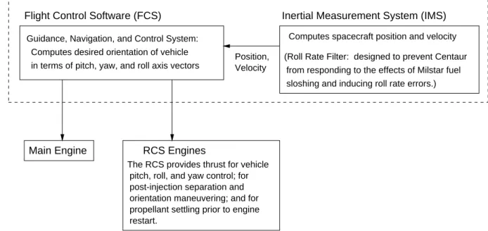
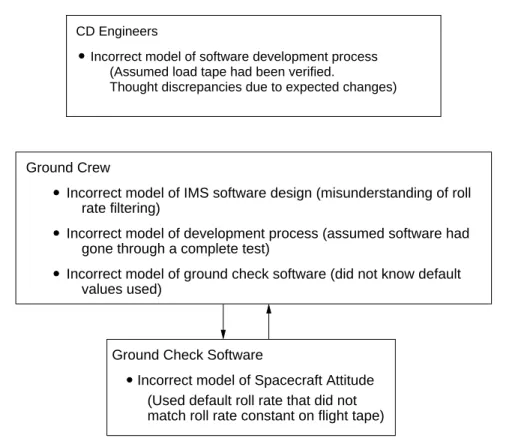
Failure of the Titan IV B-32 mission is due to a failed software development, testing, and quality assurance process for the Centaur upper stage. That failed process did not detect and correct a human error in the manual entry of the I1(25) roll rate filter constant entered in the Inertial Measurement System flight software file.
The value should have been entered as -1.992476, but was entered as -0.1992476.
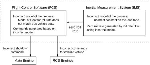
Evidence of the incorrect I1(25) constant appeared during launch processing and the launch countdown, but its impact was not sufficiently recognized or understood and, consequently, not corrected before launch. The incorrect roll rate filter constant zeroed any roll rate data, resulting in the loss of roll axis control, which then caused loss of yaw and pitch control. The loss of attitude control caused excessive firings of the Reaction Control system and subsequent hydrazine depletion. Erratic vehicle flight during the Centaur main engine burns caused the Centaur to achieve an orbit apogee and perigee much lower than desired, which resulted in the Milstar separating in a useless low final orbit [18, p. 2].
Fully understanding this accident requires understanding why the error in the roll rate filter constant was introduced in the load tape, why it was not found during the load tape production process and internal review processes, why it was not found during the extensive independent verification and validation effort applied to this software, and why it was not detected during operations at the launch site. In other words, why the safety control structure was ineffective in each of these instances.
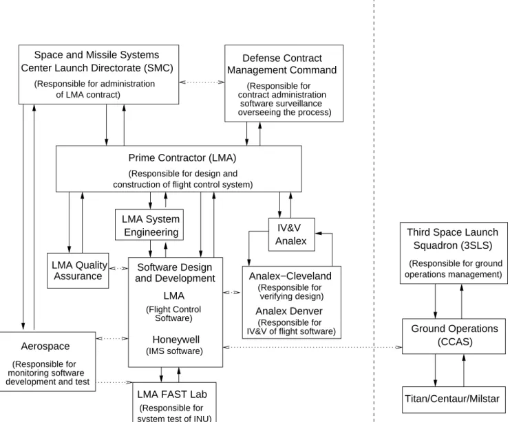
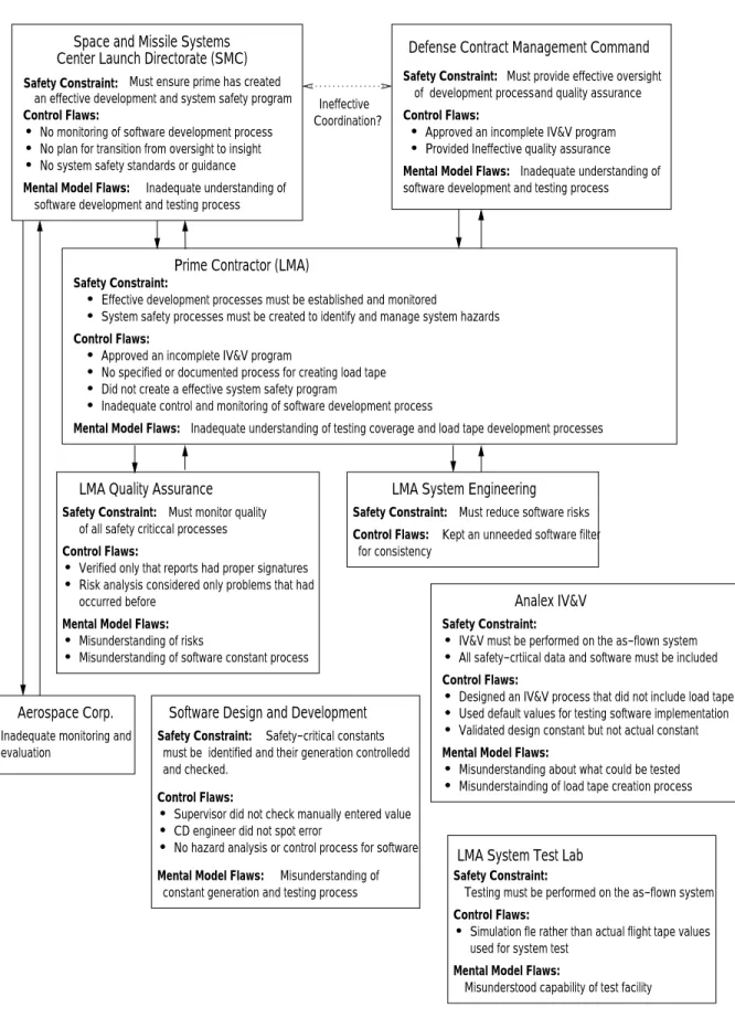
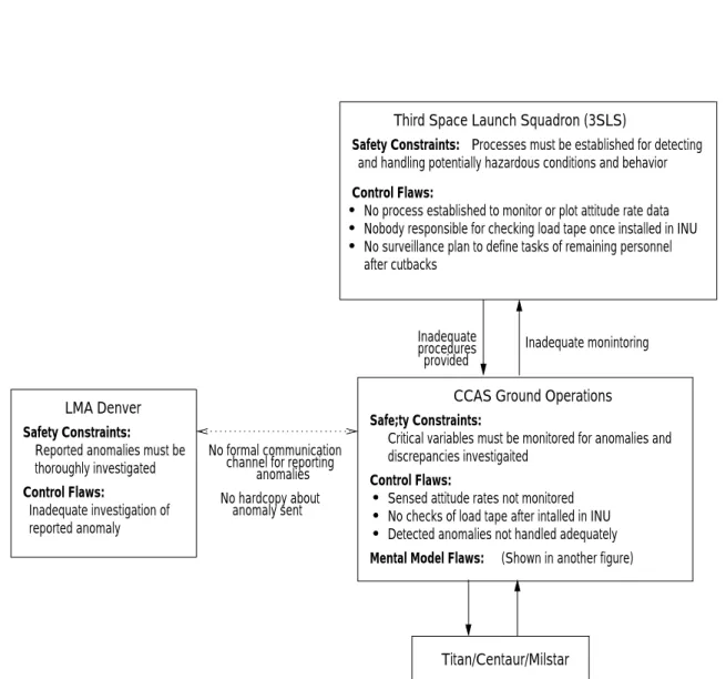
Figure 5 shows the hierarchical control model of the accident, or at least those parts that can be gleaned from the official accident report 3 . Lockheed Martin Astronautics (LMA) was the prime contractor for the mission. The Air Force Space and Missile Systems Center Launch Directorate (SMC) was responsible for insight and administration of the LMA contract. Besides LMA and SMC, the Defense Contract Management Command (DCMC) played an oversight role, but the report is not clear about what exactly this role was beyond a general statement about responsibility for contract management, software surveillance, and overseeing the development process.
LMA designed and developed the flight control software, while Honeywell was responsible for the IMS software. This separation of control, combined with poor coordination, accounts for some of the problems that occurred. Analex was the independent verification and validation (IV&V) contractor, while Aerospace Corporation provided independent monitoring and evalu- ation. Ground launch operations at Cape Canaveral Air Station (CCAS) were managed by the Third Space Launch Squadron (3SLS).
Starting from the physical process and working up the levels of control, an analysis based on a systems-theoretic accident model examines each level for the flaws in the process at that level that provided inadequate control of safety in the process level below. The process flaws
3