Review
Navigation Systems for Treatment
Planning and Execution of Percutaneous Irreversible Electroporation
Irene Fuhrmann, MSc
1, Ute Probst, MSc
1, Philipp Wiggermann, Prof. Dr
1, and Lukas Beyer, PD, Dr
1Abstract
The application of navigational systems has the potential to improve percutaneous interventions. The accuracy of ablation probe placement can be increased and radiation doses reduced. Two different types of systems can be distinguished, tracking systems and robotic systems. This review gives an overview of navigation devices for clinical application and summarizes first findings in the implementation of navigation in percutaneous interventions using irreversible electroporation. Because of the high number of navigation systems, this review focuses on commercially available ones.
Keywords
interventional radiology, navigation, robotic, percutaneous intervention, ablation, irreversible electroporation
Abbreviations
CBCT, cone-beam CT; CT, computed tomography; HFJV, high-frequency jet ventilation; IRE, irreversible electroporation; MWA, microwave ablation; RFA, radiofrequency
Received: December 14, 2017; Revised: May 01, 2018; Accepted: June 13, 2018.
Introduction
Ablative treatment techniques are very important in radioon- cological treatment. Regarding primary and secondary liver tumors, ablative strategies, liver resection, and transplantation are important treatment options.1 To further improve proce- dures, development was done especially regarding assistance in trajectory planning and placement of the ablation probes, involving navigational devices and image registration. In all ablative methods which use probes (eg, electrodes, microwave antennae), the placement of those probes is crucial for success- ful treatment. The ablation area has to cover the entire tumor tissue, therefore the ablation area is planned to be bigger than the lesion; usually a margin of 1 cm is considered adequate.2,3 Radiofrequency (RFA) and microwave ablation (MWA) are established ablation methods that are used most frequently.
Both methods produce heat in the targeted tissue to induce coagulative cell necrosis and usually use only 1 probe.4-6Both RFA and MWA are limited by tumor location and cannot be used in the vicinity of heat-sensitive structures such as colon,
stomach, or gallbladder or highly vascularized organs such as the pancreas. Further, the so-called heat sink effect can reduce the ablational success near large blood vessels.7Irreversible electroporation (IRE), in contrast, uses electrical current to induce cell death. Several electrodes are placed around the tumor and short pulses of voltages up to 3 kV are applied. The electrical current causes the cell membranes to form nanopores, resulting in apoptosis of the cells. With IRE, ablation of tumors near to heat-sensitive structures and blood vessels is possible since the treatment spares connective tissue architecture and blood vessels. The safety of IRE ablating tumors in close prox- imity of vasculature and major bile ducts has been
1Department of Radiology, University Hospital Regensburg, Regensburg, Germany
Corresponding Author:
Irene Fuhrmann, MSc, Department of Radiology, University Medical Center Regensburg, 93042 Regensburg, Germany.
Email: irene.fuhrmann@ukr.de
Creative Commons Non Commercial CC BY-NC: This article is distributed under the terms of the Creative Commons Attribution-NonCommercial 4.0 License (http://www.creativecommons.org/licenses/by-nc/4.0/) which permits non-commercial use, reproduction and distribution of the work without further permission provided the original work is attributed as specified on the SAGE and Open Access pages (https://us.sagepub.com/en-us/nam/open-access-at-sage).
Technology in Cancer Research &
Treatment Volume 17: 1-8 ªThe Author(s) 2018 Article reuse guidelines:
sagepub.com/journals-permissions DOI: 10.1177/1533033818791792 journals.sagepub.com/home/tct
demonstrated.8-11Opposing the broad scope of application, the placement of several electrodes is time-intensive and therefore cost-intensive. Further, to ensure a successful ablation, the electrodes must be placed in parallel orientation to each other.12-14
Different approaches in guiding the interventionist are avail- able and still in the process of development. Tracking systems trace the movement of the instrument. Contrarily, robotic sys- tems do not track the moving instrument but are calibrated to the computed tomography (CT) scanner and provide active guidance of the ablation probe. This review gives an overview of currently commercially available navigation devices for clinical application and summarizes first findings of our work- ing group in the implementation of navigation in IRE interventions.
Navigation in General
Navigational devices enable the guidance of an instrument into and within the patient’s body. Depending on the system, the entry side, the angle, and the depth of the ablation probes can be determined beforehand or controlled during the procedure.
Image processing and sometimes also image fusion are used to provide information for planning and verification of both probe placement and technical success. Therefore, pre- and postinter- ventional images are acquired. Most navigation systems are based on CT imaging. The components of the navigation sys- tems can be integrated into a “normal” interventional CT
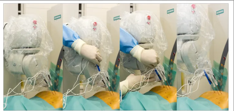
operating room (Figure 1). Some system workstations allow segmentation of the target organ and definition of functional structures and tumor area. An overview of the navigation sys- tems is given in Table 1.
Most systems work with conventional CT systems under fluoroscopy. Using cone-beam CT (CBCT) for guided inter- ventions is possible as well, depending on the system. In gen- eral, studies have shown that CBCT provides additional information during guided ablational interventions.15,16 The radiation dose is difficult to compute and is reported controver- sially for CBCT interventions.17,18Braaket alreported a reduc- tion in patient’s radiation dose of 13%to 42%but mentions a possibly increased radiation dose for the operator.19Further, a phantom study reported higher accuracy comparing guided CBCT and guided CT needle placements.15
By now in ablative treatment, navigation systems are mostly used for RFA and MWA interventions. The fundamental dif- ference between RFA/MWA navigation and IRE navigation is the requirement to plan and execute multiprobe positioning.
Although single-needle bipolar IRE probes are being devel- oped,20 those are still in experimental status and most IRE interventions performed use several electrodes, typically 4 to 6. Therefore, multiprobe placement including the need for par- allel probe placement is the greatest challenge faced in the clinical IRE routine. The difference in navigation of thermal ablation and IRE intervention thus lies more in aspects of soft- ware calculation than in technical aspects. Many systems are therefore able to guide thermal and nonthermal ablations, since Figure 1. Operating room with a stereotactic system setup. Equipment required for the guided intervention is numbered: (1) camera for optical acquisition; (2) monitor for planning; (3) monitor for real-time 3-D visualization of the guidance device; (4) fiducial markers; (5) manually positioned arm with probe guidance device (CAS-One I; CAScination AG).
the difference is rather software than hardware related. Differ- ent probes can be guided using specific adapters easily moun- table to the actual device.
Tracking Systems
To enable real-time tracking of the instruments, tracking sys- tems can be based on electromagnetic or optical detection.
Fiducial markers mounted on the instruments allow to capture the instrument’s movements and display them on the screen in real time. To register the patient’s location, additional markers are placed on the skin during preinterventional image acquisi- tion. The markers are used to link the position of the patient with the position of the instrument. Thus, trajectory paths can be visualized and planned.
An available electromagnetic navigation system for CT- guided procedures (IMACTIS-CT, IMACTIS, Grenoble, France) tracks the instrument in real time. Planning and ver- ification functions are not included. The system was recently validated in a randomized clinical study covering percutaneous CT-guided interventions, including 5 ablative procedures (RFA, MWA, and cryotherapy). Accuracy of needle placement was increased significantly and fewer control scans were required in the navigated interventions.21 A second study is currently running, again covering exclusively thermal ablation methods.22 The application of this system in IRE procedures needs to be evaluated subsequently.
Another commercially available tracking system specifi- cally developed for percutaneous tumor ablation (CAS-One IR; CAScination AG, Bern, Switzerland) is based on stereo- tactic registration. An optical sensor registers fiducial markers on the skin and the ablation probe (Figure 2). After preinter- ventional imaging of the patient, the placement of the probes is planned. The software assists the interventionist in the manual insertion of the ablation probe by comparing the planned path with the actual trajectory. This optical system was validated in a liver phantom study, showing an increase in lateral accuracy of probe insertion.23Further, the clinical safety of the system was confirmed in a study treating liver lesions with MWA. The accuracy of probe placement was found to be high and com- parable with other navigation systems.24Recently, application in IRE interventions was evaluated as well as described below in greater detail.25
Robotic Systems
In contrast to tracking systems, robot-assisted systems do not trace the instrument. Robotic systems rather provide active guidance for the placement of the instruments. A robotic arm moves to the correct position and predefines entry point, angle, and, depending on the device, also depth of the ablation probe.
Similar to the tracking systems, a registration of the positions of the robotic device and the patient has to be performed pre- interventionally. In some systems, the device can be docked to the CT table via a ground plate and calibrated to the CT. Other possibilities for registration are electromagnetic tracking, opti- cal tracking, or laser alignment processes. Trajectory paths can be planned at the system workstation. The robotic arm moves to the set position and enables insertion of the ablation probe through a holder. Correct probe position is confirmed by con- trol imaging, analogous to the manual approach. At the moment, 2 different robotic systems are commercially avail- able for percutaneous interventions.
A widely used system for percutaneous ablations (Maxio;
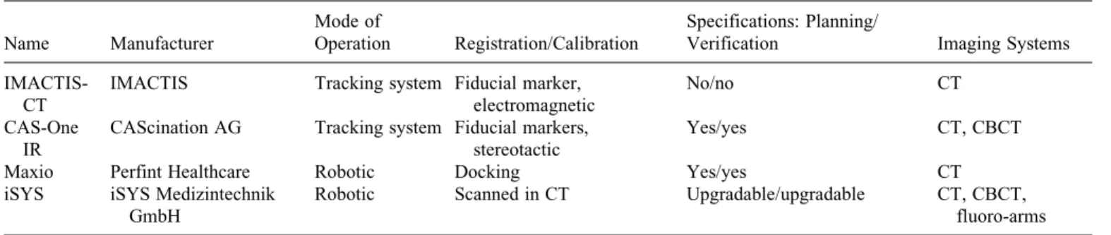
Perfint Healthcare, Chennai, India) uses docking on a ground plate for registration. The robotic arm provides active guidance during probe placement, defining entry point, angle, and depth (Figure 3). In studies treating hepatic tumors with navigated Table 1.Overview Over Commercially Available Navigation Systems for Percutaneous Interventions.
Name Manufacturer
Mode of
Operation Registration/Calibration
Specifications: Planning/
Verification Imaging Systems
IMACTIS- CT
IMACTIS Tracking system Fiducial marker, electromagnetic
No/no CT
CAS-One IR
CAScination AG Tracking system Fiducial markers, stereotactic
Yes/yes CT, CBCT
Maxio Perfint Healthcare Robotic Docking Yes/yes CT
iSYS iSYS Medizintechnik GmbH
Robotic Scanned in CT Upgradable/upgradable CT, CBCT,
fluoro-arms Abbreviation: CBCT, cone-beam computed tomography; CT, computed tomography.
Figure 2. Stereotactic device during an irreversible electroporation of a primary liver tumor. Fiducial markers on the instrument (arrow) and on the skin (arrowhead) enable registration of their respective posi- tions (using CAS-One I; CAScination AG).
Fuhrmann et al 3
MWA, the insertion time and accuracy of probe placement was improved. Further, the patient radiation dose was reduced com- pared to manual interventions under CT fluoroscopy.26,27 A study including both RFA and MWA found good accuracy in probe placement in the navigated procedure as well, but no significant decrease in patient radiation dose.28
Another available, relatively small device (266 mm 139 mm68 mm) is mounted to the CT table (iSYS; iSYS Medizintechnik GmbH, Kitzbuehel, Austria). The registration is achieved by attaching radiopaque markers on the robotic device in the preinterventional CT image acquisition. The device is positioned grossly at the CT table. The fine position- ing is possible either outside the gantry or inside under fluoro- scopy via a remote control. Even though it is promoted to be used for liver ablations, the currently available studies cover neurosurgical procedures, for example, biopsy and catheter placement. Those studies showed decrease in radiation dose for staff and expenditure of time. Precision of needle placement was increased significantly.29,30
Application in IRE
Our workgroup conducts percutaneous ablations with both kinds of navigation devices, a stereotactic tracking system and a robot-assisted system. To the best of our knowledge, these are the only studies about navigated IRE tumor ablations available up to date.
We have published a small series of IRE interventions in the liver to compare the value of stereotactic-guided and manual electrode placement.31First intended as an internal evaluation,
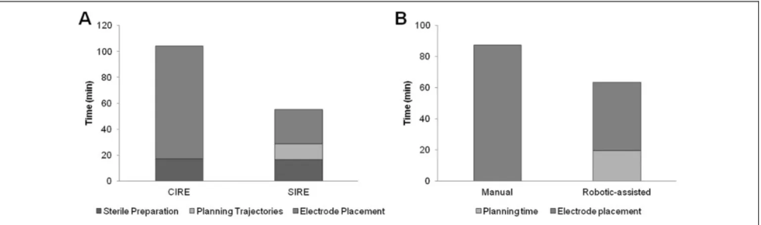
the comparison of 20 cases, 10 performed guided and 10 per- formed manually, showed a remarkable advantage of the guided procedure. Percutaneous ablation of hepatic tumors was performed under general anesthesia with deep muscle relaxa- tion. The manual approach was performed under CT fluoro- scopy without guiding assistance. For the navigated approach, fiducial markers were placed on the patients’ skin before the planning CT, the tumor was segmented, and the trajectory path was planned with the navigation system software. The probe guidance device was aligned via fiducial markers as well and positioned manually to the predefined position. The positioning can be controlled on the monitor in real time. After the inser- tion of the electroporation probes, the IRE was conducted the same way as in the manual approach following the manufac- turer’s instructions (NanoKnife System; AngioDynamics, Latham, New York). Complications occurred neither in the manual nor in the guided patient group. The total intervention time including patient preparation, trajectory planning, and electrode placement until the start of ablation was significantly reduced, approximately halved (104 vs 55 minutes;P< .001;
Figure 4). Accuracy of probe placement was measured as the deviation of the IRE electrodes with respect to a defined reference electrode and was significantly higher in the guided IRE (2.2 vs 3.3 mm mean deviation,P< .001) than in the manual procedure (Table 2). The CT-caused radiation exposure was significantly lower in the guided IRE compared to the manual approach per- formed with fluoroscopy. Technical success rate did not differ between the 2 approaches. At the follow-up, 6 weeks after the IRE, all 20 cases showed complete ablation without residual tumor tissue, which was considered technical success.
Figure 3. Robot-assisted irreversible electroporation (IRE) of a liver metastasis. The robotic arm positions itself according to the predefined plan (A) and the physician applies the probe through the probe guide (B and C). The robotic arm moves to the position of the next electrode (D;
using MAXIO Perfint Healthcare).
In another study, we compared robot-assisted IRE procedure to manual IRE under CT fluoroscopy.24Of total 40 cases, 21 were performed with robotic assistance. Seven of the lesions treated under robotic assistance were hepatocellular carcino- mas and the remaining 14 were secondary liver metastases. The IRE interventions were again performed under general anesthe- sia and following the manufacturer’s instructions. In the robot- assisted approach, the navigational system was calibrated via a docking mechanism to the CT table. No further registration or calibration was necessary as the robotic arm carrying a probe applicator locates itself spatially. The planning CT scan was sent to the system’s workstation. Bones are detected automat- ically and liver and tumor tissue are segmented with the soft- ware. The intervention is planned determining entry points, target points, and checking the trajectories for conflict with critical structures such as bones and vessels. After approval of the plan, the robotic arm moves to the defined positions, specifying the respective puncture direction and depth. The physician then inserts the electrode through the probe applica- tor. After placement of all electrodes, a control CT scan was performed. In 7 cases, the physician decided to manually cor- rect the position of the electrodes. Afterward, the standard IRE ablation was performed. The total intervention time from the planning CT scan to the start of the ablation significantly decreased using robotic assistance (64 vs 87 minutes, P <
.001; Figure 4) as well as the radiation exposure. The proce- dural accuracy was significantly higher using robotic guidance (Table 2). There were no complications in both groups. Six weeks after the intervention, the technical success was evalu- ated by a 3-phase CT scan and magnetic resonance imaging of
the liver. Residual tumor tissue was documented in 1 case with manual ablation (5.3%, 1 of 19 cases) and in none of the guided cases.
Overall, the implementation of navigation systems in IRE interventions facilitates this ablative technique. The placement of several electrodes without colliding with critical structures, with the highest possible degree of parallelism and resulting in a proper electrode geometry for IRE, is tedious. The navigation systems improve the treatment by increasing the accuracy of electrode placement and shortening the intervention time.
Advantages and Difficulties
All systems provide valuable advantages for the intervention- ist. Probes can be placed faster and more precisely than in a manual approach. Comparing the virtually planned probe posi- tions and the actual physical positions of the probes, probes placed under guidance reach the planned target more closely than those in the manual approaches. If included, the option to plan trajectory paths at the workstation facilitates working near critical structures. However, this additional step in the work- flow costs time. Additionally, the setting up of the systems needs extra time, but this factor is influenced by experience of the medical staff. Generally, the time effectiveness of guided interventions increases with a higher number of probes. There- fore, IRE interventions and multiprobe MWAs have great potential to benefit from the use of navigation devices.
Breathing motion complicates both manual and guided intervention. Moving organs during the breathing cycle are problematic, especially when ablation probes are inserted.
Figure 4. Duration of manual and guided irreversible electroporation (IRE) interventions. A, Nonnavigated conventional IRE (CIRE, total time
¼104.1 minutes) and navigated stereotactic IRE (SIRE, total time¼55.2 minutes). B, Nonnavigated manual IRE (total time¼87.4 minutes) and robotic-assisted navigated IRE (total time¼63.5 minutes).
Table 2.Accuracy of Probe Placement in Guided and Unguided IRE Intervention.a,25,31
Probe Placement Manual Guided Significance
Tracking system 3.3+1.2 mm (range: 0.8-6.2 mm) 2.2+0.9 mm (range: 0.6-4.0 mm) P< .001 (ttest) Robotic system 3.1+1.2 mm (range: 0.2-6.2 mm) 2.2+1.0 mm (range: 0.0-4.0 mm) P< .001 (Utest) Abbreviation: IRE, irreversible electroporation.
aValues given in mm+standard deviation.
Fuhrmann et al 5
There are several strategies to cope with this difficulty in breathing and ventilated patients. In spontaneously breathing patients under local anesthesia, respiratory gating techniques are common. Since organs have the same shape and position at identical time points throughout the breathing cycle, it is pos- sible to insert ablation probes at certain time points. To identify those time points, biofeedback using a respiratory belt can be applied. With this system, it can be assured that the patient’s breath-holds are in the same breathing phase during the CT scan and probe insertion.32Another approach is using optical registration of fiducial markers on the skin to deduce the breathing cycle phase.33
In principle, higher accuracy is achieved in patients under general anesthesia. There are 2 strategies for intubated patients.
First, temporary disconnection of the endotracheal tube and second, high-frequency jet ventilation (HFJV). In HFJV, short pulses of small volumes of pressurized gas are delivered with high respiratory rates. This technique of mechanical ventilation results in minimal movement of lung and abdominal organs and is feasible for long durations.34,35
Specialized image processing is of great importance for navigated systems. The implementation of automated segmen- tation of both organ and target tissue is likely to be more and more applied in the future. By now, there are many approaches in segmentation of, for example, the liver and respective target tissue in ablational interventions using manual, half-automated, or fully automated segmentation.36-39 Typical parameters for CT scanning are varying; image resolutions of 0.5 mm 0.5 mm to 0.9 mm0.9 mm, slice thicknesses of 1 to 7 mm (typically around 2 mm), and tube voltages of 100 to 120 kV are reported.39,40However, the registration of pre-, peri-, and postinterventional images is especially difficult in soft tissue as they are prone to deformation. Registration of abdominal ima- ging remains challenging. In addition to registration accuracy, the required time for the registration process is essential. To be implemented in clinical routine, the process should not delay the interventional procedure.40-42For IRE interventions, appro- priate planning of electrode geometry and electrical parameters (pulse frequency, amplitude, etc) is crucial. Advances are being made in this field of the so-called numerical treatment plan- ning.43-45
Future Aspects and Conclusion
To improve navigated percutaneous interventions in the future, modeling of tissue deformation would be valuable. When working with soft tissue, the targeted organ can be affected during the insertion of the probe. Modeling of such organ deformation seems to be difficult but would further improve accuracy. Another feature that probably will be becoming more important in the future is an immediate control of technical ablational success. After segmentation, the ablated area and the tumor area can be registered and compared. This information could help to minimize the numbers of local recurrences. Some software packages already include image registration but the first commercial software designated to ablative intervention
was released recently (NEUWAVE Ablation Confirmation;
Ethicon, Somerville, New Jersey). The image registration in all 3 planes allows easy assessment of technical success. Other manufacturers are working on similar solutions, so there is some change in this field to be expected in the future.
Additionally, the permanent integration of such navigational systems to the CT device would greatly improve the overall treatment time, as no extra setup would be necessary. Further, ablative procedures could be improved with more advanced tracking systems that account for patient breathing motion (eg, similar to those already in use for radiation therapy).
In conclusion, navigation assistance comprises great poten- tial for percutaneous interventions. Especially, IRE treatments can benefit from the implementation of guiding devices. The need to place several electrodes with high precision is challen- ging. Application of navigational systems can help to improve accuracy in probe placement and limit repositioning of probes.
Further, since IRE can be applied near critical structures such as vessels or nerves, trajectory paths are more complex to plan compared with RFA and MWA procedures. The ability to place ablation probes without CT fluoroscopy generally reduces the radiation dose for patient and physician. Further, time and cost saving is of great importance in our modern clinical everyday life. Speeding up procedures by implementing navigational assistance is also beneficial in this aspect.
Declaration of Conflicting Interests
The author(s) declared no potential conflicts of interest with respect to the research, authorship, and/or publication of this article.
Funding
The author(s) received no financial support for the research, author- ship, and/or publication of this article.
ORCID iD
Irene Fuhrmann, MSc http://orcid.org/0000-0001-9532-9973
References
1. Sauerbruch T, Appenrodt B, Schmitz V, Spengler U. The conser- vative and interventional treatment of the complications of liver cirrhosis: part 2 of a series on liver cirrhosis.Dtsch Arztebl Int.
2013;110(8):126-132.
2. Sala M, Llovet JM, Vilana R, et al. Initial response to percuta- neous ablation predicts survival in patients with hepatocellular carcinoma.Hepatology. 2004;40(6):1352-1360.
3. Mulier S, Ni Y, Jamart J, Ruers T, Marchal G, Michel L. Local recurrence after hepatic radiofrequency coagulation: multivariate meta-analysis and review of contributing factors.Ann Surg. 2005;
242(2):158-171.
4. Gazelle GS, Goldberg SN, Solbiati L, Livraghi T. Tumor ablation with radio-frequency energy.Radiology. 2000;217(3):633-646.
5. Simon CJ, Dupuy DE, Mayo-Smith WW. Microwave ablation:
principles and applications. Radiographics. 2005;25(suppl 1):
S69-S83.
6. Lubner MG, Brace CL, Hinshaw JL, Lee FT Jr. Microwave tumor ablation: mechanism of action, clinical results, and devices.
J Vasc Interv Radiol. 2010;21(suppl 8):S192-S203.
7. Pillai K, Akhter J, Chua TC, et al. Heat sink effect on tumor ablation characteristics as observed in monopolar radiofrequency, bipolar radiofrequency, and microwave, using ex vivo calf liver model.Medicine (Baltimore). 2015;94(9):e580.
8. Kingham TP, Karkar AM, D’Angelica MI, et al. Ablation of perivascular hepatic malignant tumors with irreversible electro- poration.J Am Coll Surg. 2012;215(3):379-387.
9. Narayanan G, Bhatia S, Echenique A, Suthar R, Barbery K, Yri- zarry J. Vessel patency post irreversible electroporation.Cardio- vasc Intervent Radiol. 2014;37(6):1523-1529.
10. Silk MT, Wimmer T, Lee KS, et al. Percutaneous ablation of peribiliary tumors with irreversible electroporation.J Vasc Interv Radiol. 2014;25(1):112-118.
11. Jourabchi N, Beroukhim K, Tafti BA, Kee ST, Lee EW. Irrever- sible electroporation (NanoKnife) in cancer treatment.Gastroint- est Intervent. 2014;3(1):8-18.
12. Davalos RV, Mir LM, Rubinsky B. Tissue ablation with irrever- sible electroporation.Ann Biomed Eng. 2005;33(2):223-231.
13. Rubinsky B, Onik G, Mikus P. Irreversible electroporation: a new ablation modality—clinical implications.Technol Cancer Res Treat. 2007;6(1):37-48.
14. Edd JF, Davalos RV. Mathematical modeling of irreversible elec- troporation for treatment planning. Technol Cancer Res Treat.
2007;6(4):275-286.
15. Busser WM, Braak SJ, Futterer JJ, et al. Cone beam CT guidance provides superior accuracy for complex needle paths compared with CT guidance.Br J Radiol. 2013;86(1030):20130310.
16. Abi-Jaoudeh N, Venkatesan AM, Van der Sterren W, Radaelli A, Carelsen B, Wood BJ. Clinical experience with cone-beam CT navi- gation for tumor ablation.J Vasc Interv Radiol. 2015;26(2):214-219.
17. Orth RC, Wallace MJ, Kuo MD. C-arm cone-beam CT: general principles and technical considerations for use in interventional radiology.J Vasc Interv Radiol. 2008;19(6):814-820.
18. Bapst B, Lagadec M, Breguet R, Vilgrain V, Ronot M. Cone beam computed tomography (CBCT) in the field of interventional oncol- ogy of the liver.Cardiovasc Intervent Radiol. 2016;39(1):8-20.
19. Braak SJ, van Strijen MJ, van Es HW, Nievelstein RA, van Hee- sewijk JP. Effective dose during needle interventions: cone-beam CT guidance compared with conventional CT guidance.J Vasc Interv Radiol. 2011;22(4):455-461.
20. Wandel A, Ben-David E, Ulusoy BS, et al. Optimizing irreversi- ble electroporation ablation with a bipolar electrode.J Vasc Interv Radiol. 2016;27(9):1441-1450.e1442.
21. Durand P, Moreau-Gaudry A, Silvent AS, et al. Computer assisted electromagnetic navigation improves accuracy in computed tomography guided interventions: a prospective randomized clin- ical trial.PLos One. 2017;12(3):e0173751.
22. Rouchy R, Moreau-Gaudry A, Chipon E, et al. Evaluation of the clinical benefit of an electromagnetic navigation system for CT- guided interventional radiology procedures in the thoraco- abdominal region compared with conventional CT guidance (CTNAV II): study protocol for a randomised controlled trial.
Trials. 2017;18(1):306.
23. Wallach D, Toporek G, Weber S, Bale R, Widmann G. Compar- ison of freehand-navigated and aiming device-navigated targeting of liver lesions.Int J Med Robot. 2014;10(1):35-43.
24. Engstrand J, Toporek G, Harbut P, Jonas E, Nilsson H, Freedman J. Stereotactic CT-guided percutaneous microwave ablation of liver tumors with the use of high-frequency jet ventilation: an accuracy and procedural safety study.AJR Am J Roentgenol.
2017;208(1):193-200.
25. Beyer LP, Pregler B, Michalik K, et al. Evaluation of a robotic system for irreversible electroporation (IRE) of malignant liver tumors: Initial results. Int J Comput Assist Radiol Surg. 2017;
12(5):803-809.
26. Mbalisike EC, Vogl TJ, Zangos S, Eichler K, Balakrishnan P, Paul J. Image-guided microwave thermoablation of hepatic tumours using novel robotic guidance: an early experience.Eur Radiol. 2015;25(2):454-462.
27. Beyer LP, Pregler B, Niessen C, et al. Robot-assisted microwave thermoablation of liver tumors: a single-center experience.Int J Comput Assist Radiol Surg. 2016;11(2):253-259.
28. Abdullah BJJ, Yeong CH, Goh KL, et al. Robotic-assisted thermal ablation of liver tumours.Eur Radiol. 2015;25(1):246-257.
29. Czerny C, Eichler K, Croissant Y, et al. Combining C-arm CT with a new remote operated positioning and guidance system for guidance of minimally invasive spine interventions.J Neurointerv Surg. 2015;7(4):303-308.
30. Minchev G, Kronreif G, Martı´nez-Moreno M, et al. A novel min- iature robotic guidance device for stereotactic neurosurgical inter- ventions: preliminary experience with the iSYS1 robot. J Neurosurg. 2017;126(3):985-996.
31. Beyer LP, Pregler B, Nießen C, et al. Stereotactically-navigated percutaneous Irreversible Electroporation (IRE) compared to con- ventional IRE: a prospective trial.PeerJ.2016;4:e2277.
32. Locklin JK, Yanof J, Luk A, Varro Z, Patriciu A, Wood BJ.
Respiratory biofeedback during CT-guided procedures. J Vasc Interv Radiol. 2007;18(6):749-755.
33. Lin Q, Yang R, Cai K, Guan P, Xiao W, Wu X. Strategy for accurate liver intervention by an optical tracking system.Biomed Opt Express. 2015;6(9):3287-3302.
34. Abderhalden S, Biro P, Hechelhammer L, Pfiffner R, Pfammat- ter T. CT-guided navigation of percutaneous hepatic and renal radiofrequency ablation under high-frequency jet ventilation:
feasibility study.J Vasc Interv Radiol. 2011;22(9):1275-1278.
35. Denys A, Lachenal Y, Duran R, Chollet-Rivier M, Bize P. Use of high-frequency jet ventilation for percutaneous tumor ablation.
Cardiovasc Intervent Radiol. 2014;37(1):140-146.
36. Luu HM, Klink C, Niessen W, Moelker A, van Walsum T. An automatic registration method for pre- and post-interventional CT images for assessing treatment success in liver RFA treatment.
Med Phys. 2015;42(9):5559-5567.
37. Hocquelet A, Trillaud H, Frulio N, et al. Three-dimensional mea- surement of hepatocellular carcinoma ablation zones and margins for predicting local tumor progression.J Vasc Interv Radiol.
2016;27(7):1038-1045.e1032.
38. Tani S, Tatli S, Hata N, et al. Three-dimensional quantitative assessment of ablation margins based on registration of pre- and
Fuhrmann et al 7
post-procedural MRI and distance map. Int J Comput Assist Radiol Surg. 2016;11(6):1133-1142.
39. Luu HM, Klink C, Niessen W, Moelker A, Walsum T. Non-rigid registration of liver CT images for CT-guided ablation of liver tumors.PLoS One. 2016;11(9):e0161600.
40. Xu Z, Lee CP, Heinrich MP, et al. Evaluation of six registration methods for the human abdomen on clinically acquired CT.IEEE Trans Biomed Eng. 2016;63(8):1563-1572.
41. Gunay G, Luu MH, Moelker A, van Walsum T, Klein S. Semi- automated registration of pre- and intraoperative CT for image- guided percutaneous liver tumor ablation interventions. Med Phys. 2017;44(7):3718-3725.
42. Elhawary H, Oguro S, Tuncali K, et al. Multimodality non-rigid image registration for planning, targeting and monitoring during
CT-guided percutaneous liver tumor cryoablation.Acad Radiol.
2010;17(11):1334-1344.
43. Zupanic A, Kos B, Miklavcic D. Treatment planning of electroporation-based medical interventions: electrochemother- apy, gene electrotransfer and irreversible electroporation. Phys Med Biol. 2012;57(17):5425-5440.
44. Adeyanju OO, Al-Angari HM, Sahakian AV. The optimization of needle electrode number and placement for irreversible electro- poration of hepatocellular carcinoma.Radiol Oncol. 2012;46(2):
126-135.
45. Kos B, Voigt P, Miklavcic D, Moche M. Careful treatment plan- ning enables safe ablation of liver tumors adjacent to major blood vessels by percutaneous irreversible electroporation (IRE).Radiol Oncol. 2015;49(3):234-241.