• Keine Ergebnisse gefunden

Transformer IIE4

N/A
N/A
Protected

Academic year: 2021

Aktie "Transformer IIE4"

Copied!
8
0
0

Wird geladen.... (Jetzt Volltext ansehen)

Volltext

(1)

IIE4

Modul Electricity II

Transformer

The goal of this experiment is, on the one hand, to verify experimentally

the transformer laws of unloaded transformer, and on the other hand, the

behavior of insulating and auto transformer should be examined.

(2)
(3)

Experiment IIE4 - Transformer

The goal of this experiment is, on the one hand, to verify experimentally the transformer laws of unloaded transformer, and on the other hand, the behavior of insulating and auto transformer should be examined.

c

AP, Department of Physics, University of Basel, March 2021

(4)

1.1 Preliminary Questions

• How does a transformer function? Explain in your own words.

• Where are transformers used in the everyday life? Examples?

• Are all modern transformers according to the principles described below?

• Deduce a formula for the relationship between the primary and secondary current.

1.2 Theory

A transformer essentially consists of two coils, which are connected inductively by an iron core. The primary coil with N

1

windings is connected to an alternating voltage U

1

. Thereby, a current flows through the coil and generates a magnetic flux ∆Φ . This is described by the law of induction:

U = − N ∆Φ

∆ t (1.1)

This flux is passed through the iron core in the secondary coil, where it in turn induces a current and a voltage according to (1.1). Also:

∆Φ

∆ t = − U

1

N

1

used in

U

2

= − N

2

∆Φ

∆ t results in:

U

1

U

2

= N

1

N

2

(1.2)

Since energy conservation is guaranteed here, the power ( =

energytime

) must also be obtained. It follows that the line of the primary coil to that of the secondary coil is equivalent. The electric power is defined as follows:

P = U · I (1.3)

Thus, a connection between the primary and secondary current independent of the turns are made.

1.3 Experiment

1.3.1 Equipment

Component Number

Multimeter 2

Connecting Cables 6 Connecting Bridges 4

Voltage Source 1

Exercise Transformer 1

3

(5)

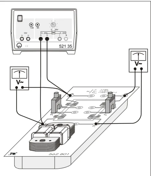
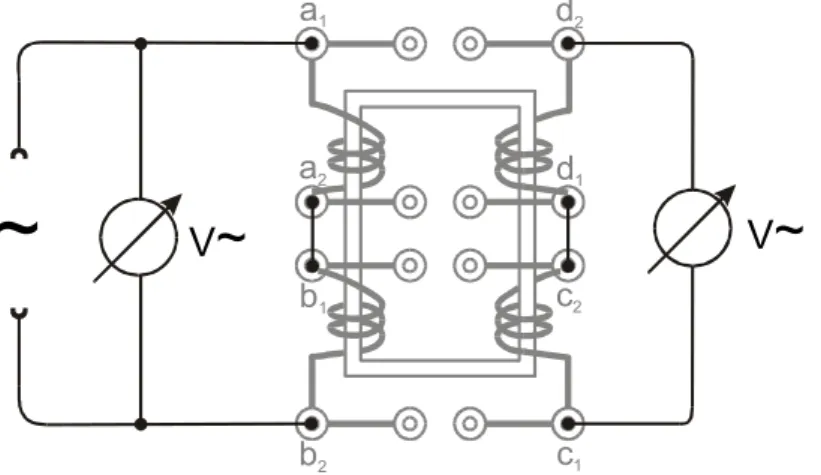
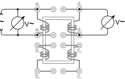
1.3.2 Experimental Setup

~

~ ~ ~

521 35

0...20V 1.8A

12V 6A

0...20V 0 20V

- +

Figure 1.1: Schematic setup of the exercise transformer with voltage source at the top on the left. Two multimeters are connected to the setup to measure the voltage V. In addition, there are two hoof-shaped plugs to connect the coils. Moreover, there is a variety of banana cables to connect the instruments with the transformer.

The exercise transformer consists of two primary and two secondary coils. Each of these four coil has 150 turns. Two coils are connected together by connecting bridges. With this setup, the following conditions

NN12

are possible: 150: 150, 150: 300, 300: 150 and 300: 300th Figure 1.1 shows schematically how the individual components are connected. If the multimeter across the coils is parallel, the voltage can be measured. They are connected in series, so we measure the (short circuit) current. The multimeter must have the appropriate position provided and experiment leads are corrected to the correct jacks. During the tests, it must be ensured that the current through the primary and secondary coils does not exceed the value of 1.5 A. After each partial test and during the conversion, the voltage source must be turned off. During the experiment, the voltage should be turned up only slowly.

4

(6)

For your own safety: Do not keep a very high current running through the transformer for longer time, because then the coils might become hot and cause a fire - or at least destroy the setup. Please check the cables for any damages and follow the manual strictly.

1.3.3 Execution and Evaluation Task a) Voltage Measurement

a

1

b

1

d

2

c

2

a

2

b

2

d

1

c

1

~ V ~ V ~

Figure 1.2: This is the scheme for the voltage measurement. On the left, there is an AC power source. The circle with the arrow stands for a multimeter and measures the AC voltage. The voltage is measured between points a

1

and b

2

and between points d

2

and c

1

. The coils on the left hand side are connected with a hoof-shaped plug between points a

2

and b

1

, similar for the coils on the right hand side between points d

1

and c

2

.

• Build the experiment for the voltage measurement.

• Choose for the turns the ratio 300:300.

• Vary the voltage at the voltage source stepwise between 0 V and 10 V and measure the voltage at the primary and secondary coil.

• Plot the value pairs in a plot, and determine the slope with a fit.

• Plot together the plot in addition to the theoretical measurements of the voltage accord- ing to Equation (1.2). Do the measured values match those of the theory?

• Repeat the experiment for the ratios 150:300 and 300:150.

Task b) Current Measurement

• Build the experiment for the current measurement.

• Choose for the turns ratio 300:300.

• Vary the voltage at the voltage source stepwise between 0V and 10V and measure the flow at the primary and secondary coil. Make sure that the power does not exceed a value of 1.5A!!

5

(7)

a

1

b

1

d

2

c

2

a

2

b

2

d

1

c

1

~

A~

A ~

Figure 1.3: This is the scheme for the current measurement. Again, an AC power source is connected on the left. The multimeters, depicted with the circle and arrow measure the current A. The coils are connected with the hoof-shaped plugs as in Figure 1.2.

• Plot the value pairs in a graph, and determine the slope with a fit.

• Plot together the plot in addition to the theoretical measurements of the current accord- ing to your formula for the current of the primary and secondary coils. Do the measured values match those of the theory?

• Repeat the experiment for the ratios 150:300 and 300:150.

Task c) The Auto Transformer

V ~

a

1

b

1

d

2

c

2

a

2

b

2

d

1

c

1

~

V ~

Figure 1.4: This is the scheme of an auto transformer. A power source is applied on the left.

With multimeters, the voltage between the points a

1

and b

2

and between a

2

and b

2

can be measured. The coils on the left hand side are connected with the hoof-plug. The coils on the right hand side are not part of this experiment.

• Build the auto transformer according to Figure 1.4.

• Vary the voltage at the voltage source stepwise between 0 V and 10 V and measure the voltage at the primary and ’secondary’ coil. Note: The secondary coil is indeed the same

6

(8)

as the primary one, but just a part of it.

• Plot the value pairs in a plot, and determine the slope with a useful fit.

• Discuss the current relation and the power relation of the auto transformer.

• What do you notice? What are the advantages and disadvantages of this setup compared to the construction of task a)?

Task d) The insulating Transformer a

1

b

1

d

2

c

2

a

2

b

2

d

1

c

1

~ V ~ V ~

Figure 1.5: This is the scheme of an insulating transformer. The power source is applied on the left and the voltage V can be measured between points a

1

and a

2

as well as between points d

2

and d

1

. The two lower coils b and c are not connected to the setup.

• Figure 1.5 shows the setup of an insulating transformer.

• Describe how the voltage and current at the secondary coil is a function of the primary coil behaviour. (You have measured a similar situation already in task a) and b).)

• Where can one use such a setup?

1.4 Literature

• Paul A. Tipler, Physik für Naturwissenschaftler und Ingenieure, Spektrum

• Horst Stöcker, Taschenbuch der Physik, Verlag Harri Deutsch

• Horowitz & Hill, The Art of Electronics, Cambridge University Press

7

Abbildung

Figure 1.1: Schematic setup of the exercise transformer with voltage source at the top on the left
Figure 1.2: This is the scheme for the voltage measurement. On the left, there is an AC power source
Figure 1.4: This is the scheme of an auto transformer. A power source is applied on the left.
Figure 1.5: This is the scheme of an insulating transformer. The power source is applied on the left and the voltage V can be measured between points a 1 and a 2 as well as between points d 2 and d 1

Referenzen

ÄHNLICHE DOKUMENTE

In the open form on the right, the user will find detailed information, for example concerning the type, the form and the medium of the survey, the time period in which it

Comparing the fine-tuned Transformer to its original protein embedding model, we show that fine-tuning on the homology landscape of the Immunoglobulin G-binding protein G does

Further, Vac1av IV.'s chancellery is characterized in the chapter three as apart of the court and I also shortly describe its history, structure as weIl as the competence of

The goal of this bachelor’s thesis is to map the activity of the border organization “Euregio Egrensis” within the purview of the project Ziel 3/Cíl 3.. The bachelor’s thesis

Initial total assets and current growth in total assets are made up from the same substance and therefore the explanation is the same as above. As to the other proxies for

As we approached Walvis Ridge at the beginning of the week the petrologists attempted unsuccessfully to sample an isolated seamount flanking Walvis Ridge to the south.. Later in

More precisely, when the market anticipates that the set of informative signals for which an informed expert decides to misreport is large, there is little updating of expertise

Algebraic eigenvalue problem, eigenvalue-eigenmatrix relations, Jordan normal form, adjugate, principal submatrices, Hessenberg matrices, eigenvector components.. AMS