complexes of dysprosium, holmium and erbium
Inaugural-Dissertation zur
Erlangung des Doktorgrades
der Mathematisch-Naturwissenschaftlichen Fakultät der Universität zu Köln
vorgelegt von
Kathrin Daub aus Köln
Köln 2009
Berichterstatter: Prof. Dr. Gerd Meyer Prof. Dr. Axel Klein
Tag der mündlichen Prüfung: 25. November 2009
Köln unter Anleitung von Prof. Dr. Gerd Meyer und von Oktober 2008 bis März 2009 am Department of Chemistry der Arizona State University, Tempe unter Betreuung von
This thesis was intended to broaden our knowledge of interstitially stabilized rare-earth cluster halides of the elements dysprosium, holmium and erbium in terms of structures and electronic situation. Especially, new compounds of the M{ZM6}I12 type could be obtained for M = Ho and Z = Fe, Co, Ni, Ir and Pt. The structure consists of monomeric {ZM6}clusters surrounded by iodide ligands and additional MI6entities interconnecting the clusters. For dysprosium, however, it was not possible to synthesize analogous cluster complexes with transition metals as interstitials, but with the C2 unit instead. Further investigations led to a phase of the composition Dy{CoDy4.53Y1.47}I12with dysprosium and yttrium atoms both forming octahedral{M6}clusters and incorporating the transition metal cobalt.
Apart from monomeric clusters, attention was focused on condensed cluster phases:
The condensation of a cluster edge resulted in the formation of bi-octahedral units in {(C2)2M10}X18 with M = Dy, X = Br and M = Er, X = I, encapsulating a C2dumbbell.
Further condensation led to the tetrameric clusters {Ru4Ho16}I28{Ho4} and {(C2)2O2Dy14}I24with the former consisting of{Ru4Ho16}I36 units comprising a tetra- hedral arrangement of ruthenium interstitials and furthermore exhibiting empty{Ho4}I8 tetrahedra resembling PrI2−V. {(C2)2O2Dy14}I24 consists of a linearly ordered double tetrahedra encapsulating oxygen atoms and flanked by octahedra containing C2 dumb- bells.
The cluster complexes {(C2)ODy6}I9, {IrHo3}I3 and {(C2)Er4}I6 represent cluster chains. {(C2)ODy6}I9consists of the same motif as{(C2)2O2Dy14}I24, just being con- densed via common octahedral edges.{IrHo3}I3contains monocapped trigonal prismatic {IrHo7} clusters that are arranged in zig-zag chains. In {(C2)Er4}I6, trans-edge con- nected{(C2)Er6} octahedra are alternately elongated and compressed depending on the orientation of the interstitial C2unit.
Band structure calculations reveal that Z-M interactions are the driving force for cluster formation and M-M interactions just play a minor role in terms of bonding.
Das Ziel dieser Arbeit bestand in der Synthese und strukturellen sowie elektronischen Untersuchung neuer interstitiell stabilisierter Selten-Erd-Halogenid-Cluster der Elemente Dysprosium, Holmium und Erbium. Vor allem konnten zahlreiche neue Verbindungen des Strukturtyps M{ZM6}I12mit M = Ho und Z = Fe, Co, Ni, Ir und Pt erhalten werden. Die Struktur besteht aus monomeren, von Iodid-Liganden umgebenen {ZM6} Clustern und zusätzlichen MI6-Einheiten, welche die Cluster untereinander vernetzen. Dagegen war es im Falle von Dysprosium nicht möglich, analoge Cluster-Komplexe mit Übergangs- metallen als interstitielle Einheiten zu synthetisieren. Stattdessen gelang der interstitielle Einbau von C2-Einheiten. Weitere Untersuchungen führten zu einer Phase der Zusam- mensetzung Dy{CoDy4.53Y1.47}I12, in welcher sowohl Dysprosium- als auch Yttrium- Atome auf den Atomlagen des{M6}-Clusters liegen und Kobalt als interstitielles Atom aufweisen.
Außer monomeren Clustern wurde das Augenmerk auf kondensierte Cluster-Verbind- ungen gelegt. Durch Kondensation einer Cluster-Kante konnten doppeloktaedrische Di- mere des Typs{(C2)2M10}X18 mit M = Dy, X = Br und M = Er, X = I erhalten werden, welche jeweils eine C2-Hantel einlagern. Durch weitere Kondensation entstanden die tetrameren Cluster {Ru4Ho16}I28{Ho4}und {(C2)2O2Dy14}I24. {Ru4Ho16}I28{Ho4} enthält {Ru4Ho16}I36-Einheiten, deren interstitielle Ruthenium-Atome in Form eines Tetraeders angeordnet sind und die u.a. durch leere {Ho4}I8-Tetraeder verknüpft wer- den, welche PrI2−V ähneln. {(C2)2O2Dy14}I24 wird aus linear angeordneten Tetrae- dern mit interstitiellem O-Atom gebildet, die wiederum nach außen von C2-enthaltenden Dy-Oktaedern begrenzt werden.
Die Cluster-Verbindungen{(C2)ODy6}I9,{IrHo3}I3und{(C2)Er4}I6stellen Cluster- Ketten dar.{(C2)ODy6}I9besteht aus dem gleichen Motiv wie{(C2)2O2Dy14}I24, ist je- doch durch gemeinsame Kanten über die Oktaeder zu Ketten kondensiert.{IrHo3}I3wird aus einfach überkappten trigonalen{IrHo7}-Prismen aufgebaut, die zu Zick-Zack-Ketten
Bildung der Metallcluster verantwortlich sind und M-M-Wechselwirkungen nur eine un- tergeordnete Rolle spielen.
Contents
1. Introduction 1
2. Materials and methods 5
2.1. Equipment . . . 5
2.1.1. Glove boxes . . . 5
2.1.2. Arc-welding furnace . . . 6
2.1.3. Furnaces . . . 6
2.1.4. Vacuum and inert gas technique . . . 6
2.1.5. Decomposition equipment . . . 6
2.1.6. High vacuum sublimation . . . 6
2.2. Experimental procedure . . . 7
2.2.1. Syntheses of the reactants . . . 9
2.3. Electronic structure calculations . . . 12
3. Isolated rare-earth clusters 14 3.1. General aspects of the structure type M{ZM6}X12 . . . 14
3.2. Crystal structures of Ho{ZHo6}I12with Z = Fe, Co, Ni, Ir, Pt . . . 16
3.3. Crystal structure of Dy{(C2)Dy6}I12 . . . 24
3.4. Crystal structure of Dy{CoDy4.53Y1.47}I12 . . . 28
3.5. Electronic structure of M{ZM6}X12type compounds . . . 32
4. Dimeric rare-earth clusters 37 4.1. Crystal structure of{(C2)2Dy10}Br18 . . . 37
5. Oligomeric rare-earth clusters 46
5.1. Crystal structure of{Ru4Ho16}I28{Ho4} . . . 47
5.2. Electronic structure of{Ru4Ho16}I28{Ho4} . . . 55
5.3. Crystal structure of{(C2)2O2Dy14}I24 . . . 57
6. Cluster chains 63 6.1. Crystal structure of{(C2)ODy6}I9 . . . 64
6.2. Crystal structure of{IrHo3}I3 . . . 69
6.3. Electronic structure of{IrHo3}I3 . . . 75
6.4. Crystal structure of{(C2)Er4}I6 . . . 77
6.5. Electronic structure of{(C2)M4}I6type compounds . . . 81
7. Summary and prospects 83
A. Appendix 96
B. Acknowledgments 107
C. Erklärung 108
D. Curriculum Vitae 110
1. Introduction
Rare-earth halides exhibiting oxidation numbers of less than three have been known since the first syntheses and characterizations of the products performed by Klemm, Bommer and Döll [1, 2]. As a result, many of them form binary halides with the composition MX2
(X=Cl, Br, I) which can be divided in two different types: the salt-like and the metallic di- halides. The salt-like dihalides are also called “real” dihalides as they consist of M2+ions with the electron configuration [Xe]4fn+15d06s0 whereas in metallic dihalides, the rare earth metal has just a formal oxidation number of +2. So the formulation (M3+)(e−)(I−) is more appropriate, emphasizing the electronic transition from an f- to a d-orbital ac- cording to the configuration [Xe]4fn5d16s0.
Apart from dihalides, reduced rare earth halides can also be obtained as intermediate phases between the dihalide and trihalide. Thus, the isostructural compounds Dy5Cl11 and Ho5Cl11 crystallize in a fluorite super-structure with additional anions according to the formulation 4 MCl2·MCl3[3, 4]. Even more reduced phases with different composi- tions such as M2X3 (e.g. Gd2Cl3) or with a monovalent rare-earth metal as observed in LaI as well as ternary halides are known [1, 5, 6].
By far the greatest structural variety is revealed in the countless cluster compounds of the electron-poor rare-earth metals which have been explored by Corbett, Simon, Meyer and co-workers over the previous two decades [7–13]. Metal clusters are predominantly formed by the early transition metals with relatively larged-orbitals. The cluster forma- tion is realized if the ratio metal/non-metal (e.g. halide) is greater than the preferred coor-
in the case of the electron-poor group three and four metals. However, the electron in- sufficiency is compensated by introducing an interstitial atom into the cluster center. The interstitial (Z) can be a non-metal like B, C, N, C2or ad-metal, mainly from group seven to group nine [14, 15], providing additional electrons for M-Z and M-M interactions. The clusters themselves consist of octahedral units and can be classified as isolated (discrete) and condensed clusters. In the case of isolated clusters (Fig. 1.1a), the M6-unit is periph- erically surrounded by halogen atoms, leading to the general composition{ZM6}Xi12Xa6 (with Xi as edge-bridging, inner ligands and Xa as terminal, outer ligands according to Schäfer [16]). Finally, these isolated clusters are connected via halogen atoms to form networks in most cases. If the ratio metal/halide is large, condensed clusters are pre- dominantly obtained, i.e. M6 clusters sharing common vertices, edges or faces and thus building chains, sheets or networks (Fig. 1.1b).
a) b)
Figure 1.1.: a){ZM6}X18cluster unit, b) chain of edge-connected M6octahedra
But apart from octahedral clusters, tetrahedral, trigonal-bipyramidal, trigonal prismatic.
cubic and square-antiprismatic clusters are known as well. As a consequence, there might be an apparent dependency of the cluster size from the size of the interstitial atom.
Status quo
Among the rare-earth halides MX2, the di-iodides MI2 (Fig. 1.2) are of great interest:
The metallic di-iodides, for instance, have interesting magnetic properties, induced by the delocalization of the 5d1 electron. A prominent example is GdI2 which is not only
ferromagnetic, but also exhibits a giant magnetoresistivity [17]. But beside the resulting magnetic effects, the 5d1 configuration can also lead to cluster formation caused by at- tractive interactions between thosed-orbitals which is realized in the extraordinary PrI2-V with tetrahedral{Pr4}clusters which are connected to each other according to the formu- lation{Pr4}I4I12/3. Another feature of PrI2is its great variety of observed modifications:
Three “metallic” (PrI2-I, CuTi2type; PrI2-II, -III, MoS2type) as well as a salt-like mod- ification (PrI2-IV, CdCl2 type) have been investigated in addition to PrI2-V [18]. The existence of these five modifications indicates a complex system and hence it is challeng- ing to yield pure phases. Despite recent research activities, not all questions have been answered satisfactorily [19].
Figure 1.2.: Rare-earth elements building “metallic” (blue), salt-like (red) or no (white) di-iodides so far.
For the other rare-earth elements, such a distinct variety of modifications has not been known so far. In the case NdI2, a transition from the salt-like (SrBr2type) to the metallic modification (CuTi2type) over an intermediate phase of the CaF2type has been observed at high pressures [20]. The transition is thought to be caused by an energetic approxima- tion of the f- and d-orbitals due to the influence of high pressure on the expansion and energy of thef- and d-orbitals and therefore enabling the transition of an electron from thef- into thed-orbital. Moreover, a pressure induced decrease of the cation-cation dis- tance evokes an improvedd-orbital overlap and therefore a larger anisotropic conductivity.
A di-iodide of holmium is not known yet, but conproportionation reactions in the sys-
[Ho9C4O]I8, Ho7I12C has been the only compound consisting of holmium halide clusters.
This is in contradiction to the rare-earth elements Sc, Y, La, Pr and Gd revealing quite a vast variety of interstitially stabilized cluster compounds [7, 10, 22, 23].
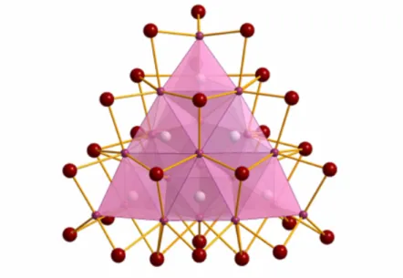
Also dysprosium halide clusters have not been well investigated until now. Solely two cluster compounds,{(C2)2Dy10}I18and{(C2)Dy4}I6, have been reported by Simon and co-workers in 2007 [24]. Other attempts of synthesizing interstitially stabilized clusters only led to the salt-like DyI2as the main product [14]. This illustrates that it is not neces- sarily the magnitude of cluster bonds to achieve successful reactions in the field of solid state chemistry, but also the relative stability of competing phases. Products are hardly predictable, therefore explorative syntheses are commonly applied. As a consequence, surprising and unpredictable, new structure types are not rare at all as it is strikingly demonstrated by the super-tetrahedron Sc24I30C10 (Fig. 1.3) [12].
Based on this knowledge, this dissertation is aimed at the synthesis of new holmium, dysprosium and - to some extent - erbium halide cluster complexes and additionally at new insights into the electronic situation in these clusters.
Figure 1.3.: Sc24I30C10: A tetrahedron composed of edge-sharing{Sc4C}tetrahedra.
2. Materials and methods
2.1. Equipment
2.1.1. Glove boxes
Because of the air and moisture sensitivity of both, reactants and products, all prepara- tions were carried out in glove boxes (MBraun, Garching, Germany) under an argon or nitrogen atmosphere with water and oxygen contents less than 1 ppm. The glove boxes contain an integrated gas purification system that permanently circulates the inert gas and purifies it through a molecular sieve and a copper catalyst. Materials can be transfered into the box through two pressure regulated antechambers. A balance (Sartorius, Göttin- gen, Germany) and a microscope (type MZ 6, Leica, Wetzlar, Germany) integrated in the box serve as tools for experimental manipulations.
2.1.2. Arc-welding furnace
Tantalum and niobium containers were exclusively used for the syntheses. After loading the partially welded containers with the reactants, the containers were closed completely by welding it using an arc-welding furnace (self construction, University of Gießen). The welding procedure was carried out under a helium atmosphere of 750 mbar and a current of 5-10 A. A tungsten needle and the tantalum/niobium container act as electrodes.
2.1.3. Furnaces
Tube furnaces with chromel/alumel and platinum/platinum-rhodium thermocouples were used for reactions not exceeding a temperature of 950◦C. For syntheses with temperatures between 950 and 1200◦C muffle furnaces (Nabertherm, Lilienthal, Germany) were used.
2.1.4. Vacuum and inert gas technique
The loaded and welded tantalum/niobium containers were encapsulated in silica ampoules under vacuum to avoid oxidation of the metal containers at high temperatures. The silica ampoule was fused at one side and after adding the metal container narrowed at the other side, fixed to the vacuum line by a “quick fit” tube, evacuated and finally entirely fused.
2.1.5. Decomposition equipment
The decomposition equipment consists of a Duran flask (length: 50 cm, diameter 7 cm) and a lid with a gas outlet. The substance is loaded on a silica shuttle and moved into the decomposition apparatus. The gas outlet is connected via a cold trap to a rotary vane pump. The decomposition apparatus is placed into a tube furnace and can undergo various temperature programs.
2.1.6. High vacuum sublimation
The high vacuum equipment (Fig. 2.2) consists of a silica sublimation tube which is put uprightly into a tube furnace and connected to a cold trap and an oil diffusion pump system. The latter contains a rotary vane pump connected upstream to an oil diffusion
pump and a vacuometer. The resulting pressure can be up to 10−6mbar. The substance is filled into a silica tube which is fused at one side and transferred into the sublimation tube. The fused silica tube is coated with another open silica tube. Due to the temperature gradient, the sublimate re-sublimates at the inner walls of the outer silica tube. After having finished the sublimation, the sublimation tube is transferred into a glove box.
Figure 2.2.: Equipment for high vacuum sublimation.
2.2. Experimental procedure
The tantalum and niobium containers were made out of a meter long tantalum tubes which were cut into ca. 4-5 cm long pieces. Afterwards they were cleaned using a solution of conc. H2SO4, HNO3and HF in the ratio of 2:1:1 in order to remove oxygen impurities.
Afterwards they were fused at one side by arc-welding and cleaned again. Then they were transfered into a glove box, filled with the reactants, completely fused and encapsulated in a silica ampoule (Fig. 2.3). The silica ampoules were put in a furnace, exposed to a computer regulated temperature program and eventually opened in a glove box. Suitable single crystals were carefully transfered into a glass capillary and checked concerning their quality by using an X-ray precision camera.
Figure 2.3.: Tantalum containers sealed in silica ampoules.
XRD measurements
Full collections of intensity data of X-ray diffraction of single crystals were carried out by the image plate diffraction systems IPDS I and II (Stoe, Darmstadt, Germany). IPDS measurements use image plates containing BaFBr : Eu2+ to measure the intensities of the diffracted X-rays. Upon exposure to X-rays, the Eu2+ ion is oxidized to Eu3+. The free electrons occupy interstitial lattice sites, forming color centers. Afterwards the im- age plates are scanned by a He/Ne laser, leading to an activation of the color centers and reducing the Eu3+ions to Eu2+again. As a result, an emission is produced which is mea- sured by a photo-electron multiplier. Then the image plate is radiated with white light to remove possibly still existing color centers.
The analysis of the intensity data was performed with the computer programs SIR- 92 [25] and SHELX-97 [26, 27]. A numerical absorption correction was carried out with the programs X-RED [28] and X-SHAPE [29].
Powder diffraction data were recorded on a Huber G 670 instrument (Huber, Rimsting, Germany) using Mo−Kα radiation. For the measurements, the samples were filled in glass capillaries with a diameter of 0.3 mm and sealed under inert gas.
Energy dispersive X-ray (EDX) spectroscopy
EDX measurements were recorded on a REM-Zeiss Neon 40 instrument. For the mea- surements, the sample was adhered to a sample holder in a glove box and rapidly trans- ferred into the instrument, minimizing the exposure to air.
2.2.1. Syntheses of the reactants
Iodides
Lanthanide(III) iodides, MI3, were synthesized directly from the elements according to the reaction 2 M+3 I2→2 MI3. The elements were filled into a silica ampoule and a catalytic amount of ammonium iodide was added.
RT25
◦C/h
−→ 100◦C5
◦C/h
−→ 150◦C10
◦C/h
−→ 185◦C(14 h)10
◦C/h
−→ 240◦C(8 h)20
◦C/h
−→ RT
Afterwards, the ampoule was opened and excessive iodine was sublimated. The product was purified by sublimation under high vacuum and transferred into a glove box.
Bromides and chlorides
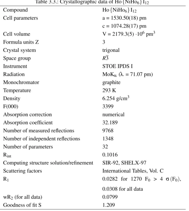
Syntheses of the lanthanide(III) bromides and chlorides were carried according to the ammonium halide route byMeyer[30]:
M2O3+6 NH4X+6 HX→2(NH4)3MX6+3 H2O 2(NH4)3MX6→2 MX3+6 NH4X
The sesquioxide was dissolved in hydrobromic (hydrochloric) acid and an excess of ammonium bromide (ammonium chloride) was added. The solution was evaporated and the almost dry substance put on a shuttle and transferred into a decomposition apparatus and exposed to the following temperature program:
RT50
◦C/h
−→ 120◦C(10h)50
◦C/h
−→ 450◦C(22h)90
◦C/h
−→ RT
Afterwards, the product was purified by sublimation under high vacuum and checked for its purity by powder X-ray diffraction.
Figure 2.4.: Scheme of the synthesis of lanthanide(III) bromides and chlorides [30].
Applied chemicals
Dysprosium blocks Chempur, Karlsruhe, Germany Dysprosium powder,≥99.9 % Chempur, Karlsruhe, Germany Holmium blocks Chempur, Karlsruhe, Germany Holmium powder,≥99.9 % Smart Elements, Vienna, Austria Erbium blocks
Yttrium blocks Chempur, Karlsruhe, Germany Yttrium powder,≥99.9 % Chempur, Karlsruhe, Germany
DyI3 powder Osram, Munich, Germany
HoI3 powder Osram, Munich, Germany
Dy2O3 powder,≥99.9 % Chempur, Karlsruhe, Germany Ho2O3 powder,≥99.9 % Chempur, Karlsruhe, Germany
NH4Cl p.a. Acros, Geel, Belgium
NH4Br p.a. Janssen, Beerse, Belgium
Iodine p.a. Acros, Geel, Belgium
HCl 32 % KMF, Lohmar, Germany
HBr 48 % Acros, Geel, Belgium
Chromium powder,≥99.9 % Merck, Darmstadt, Germany Manganese powder,≥99.9 % Chempur, Karlsruhe, Germany Iron powder,≥99.9 % Merck, Darmstadt, Germany Cobalt powder,≥99.9 % Merck, Darmstadt, Germany Nickel powder,≥99.9 % Merck, Darmstadt, Germany Copper powder,≥99.9 % Merck, Darmstadt, Germany Zinc powder,≥99.9 % Merck, Darmstadt, Germany Ruthenium powder,≥99.9 % Merck, Darmstadt, Germany Rhodium powder,≥99.9 % Merck, Darmstadt, Germany Osmium powder,≥99.9 % Degussa, Düsseldorf, Germany Iridium powder,≥99.9 % Chempur, Karlsruhe, Germany Platinum powder,≥99.9 % Chempur, Karlsruhe, Germany
Applied computer programs
X-Red [28] crystal data reduction and correction WinGX 1.63.02 [31] graphical interface
SIR-92 [25] crystal structure solution SHELXS-97 [26] crystal structure solution SHELXL-97 [27] crystal structure refinement
X-SHAPE [29] geometrical crystal optimization for absorption correction PLATON00 [32] program for checking the space group symmetry
STOE WinXPow [33] visualization of powder XRD data X-AREA [34] integration of single crystal data DIAMOND 3.0a [35] program for drawing crystal structures Origin 7.0 [36] creation of graphs and diagrams TB-LMTO-ASA [37] band structure calculations
2.3. Electronic structure calculations
Electronic structure calculations were carried out with the TB-LMTO-ASA 4.7 program using the atomic spheres approximation and employing the density functional theory (DFT) with the local density approximation for the exchange and correlation energies [37–39]. As a result the intra-atomic Coulomb interactions are neglected which are actu- ally important for systems containing elements with strongly correlating electrons. There- fore thef-electrons of the lanthanide atoms were treated as core electrons in all calcula- tions. Additionally, the local density approximation generally underestimates the band gap in semi-conductors. The following Muffin-Tin Orbitals were used as basis sets:
Ho/Dy: 6s, 5d; 6pincluded via the downfolding technique [40]
I: 6s, 5p; 5dand 4f downfolded Fe/Co/Ni: 4s, 4p, 3d
Ir: 6s, 6p, 5d; 5f downfolded Ru: 5s, 5p, 4d; 4f downfolded Tc: 5s, 5p, 4d, 4f downfolded C: 2s, 2p; 3ddownfolded
The k-points of the first Brillouin zone were chosen via the tetrahedron method [41].
The following numbers of irreducible k-points were used:
M{ZM6}X12type compounds: 690 {Ru4Ho16}I28{Ho4}: 451
{IrHo3}I3: 572 {C2Dy4}I6: 729
The calculations were interpreted on the basis of DOS curves as well as COHP analyses (crystal orbital Hamilton population) in order to gain information on the bonding situation between atoms [42].
3. Isolated rare-earth clusters
In most cases, rare-earth clusters, either isolated or condensed, derive from M6X12 units, with the halogen atoms bridging all edges of the metal octahedron. Despite their structural similarity, clusters of rare-earth halides are remarkably distinct from binary phases as they encapsulate an interstitial atom, stabilizing the electron-poor metal framework. As a result, the role of metal-interstitial bonding may be more important than that of metal- metal bonding in stabilizing the cluster phase.
In the case of isolated clusters, only the following (ternary) structure types have been synthesized so far: M{ZM6}X12 (7-12 type), {ZM6}X10 [43], {ZM6}X11 [44] and {ZM6}2X11 [45]. Rare earth cluster compounds of the general formula M{ZM6}X12, where Z is an interstitial atom, primarily a 3dmetal or a main group element, have been well explored for the rare earth elements Sc, Y, Pr and Gd [14]. Additionally, compounds of the formula Ax{ZR6}I12+y, where A is an alkali metal (Rb or Cs) with x = 1-4 and y = 0-1 and Z = C, C2, are known for the rare earth elements Pr and Er [46, 47]. In this disser- tation, the knowledge of this structure type could be extended to the elements dysprosium and holmium.
3.1. General aspects of the structure type M {ZM
6} X
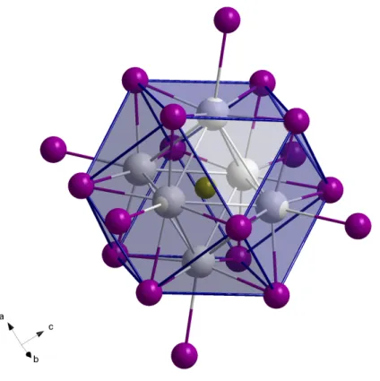
12The crystal structure of M{ZM6}X12 type compounds consists of crystallographically equivalent metal atoms forming slightly distorted octahedral clusters (D3d symmetry), whose twelve edges are bridged by twelve halogen atoms. Additionally all vertices are saturated with terminal halogen ligands. In general, the halogen ligands can be divided
into two groups: Those bridging vertices of one cluster and additionally bonding to non- cluster metal atoms along the c-axis, thus building up almost perfectly octahedral MX6 entities, and those connecting two clusters among each other by acting as edge-bridging ligands in the one cluster and terminal ligands in the other (Fig. 3.1). To sum up, the coordination sphere surrounding a metal octahedron consists of six Xi and furthermore six Xi−a and Xa−i atoms, belonging to two clusters, respectively, and leading to the for- mulation M{ZM6}Xi6Xi−a6/2Xa−i6/2.
Figure 3.1.: I3 acts as an edge-bridging ligand, additionally bonded to Ho2, whereas I4 connects two clusters among each other. Shown is the example of Ho{FeHo6}I12.
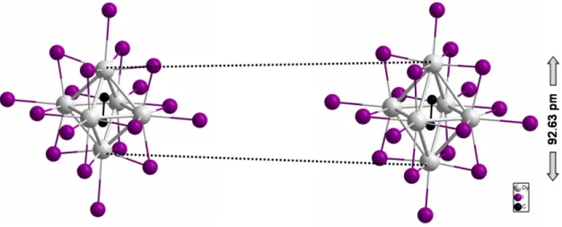
Alternatively, the structure can be described in terms of cubic-closest-packed layers of iodine atoms where every 13th iodine atom is replaced by the interstitial Z. As a result, twelve iodine atoms form a cuboctahedron centered by the interstitial Z and containing the metal atoms in octahedral sites next to the interstitial (Fig. 3.2).
Figure 3.2.: Cuboctahedron built by inner iodine atoms with the interstitial Fe in its center.
For the sake of completeness, the terminal iodine atoms are shown as well as the cluster forming metal atoms occupying octahedral sites.
3.2. Crystal structures of Ho {ZHo
6} I
12with Z = Fe, Co, Ni, Ir, Pt
Holmium compounds of the structure type M{ZM6}X12could be synthesized for the first time. In this regard, single crystals of Ho{ZHo6}I12with Z = Fe, Ni and Pt could be ob- tained whereas Ho{ZHo6}I12 with Z = Co and Ir could be characterized on the basis of powder data.
All compounds crystallize in the space group R3. Lattice constants and other crystal- lographic parameters can be found in Tabs. 3.1, 3.3 and 3.5, selected distances are listed in Tabs. 3.2, 3.4 and 3.6. Concerning the powder data, lattice constants could only be determined for Ho{CoHo6}I12.
The cell parameters of Ho{FeHo6}I12, Ho{CoHo6}I12 and Ho{NiHo6}I12 differ re- markably from each other. Even though the cell volumes of Ho{FeHo6}I12 (2153.3(5)·106pm3) and Ho{CoHo6}I12 (2151.7(38)·106pm3) are quite similar, both compounds exhibit strongly differing values for the a- and c-axes, i.e. a = 1529.73(17) pm and c = 1062.52(18) pm for Ho{FeHo6}I12and a = 1545.2(14) pm and c = 1040.7(7) pm for Ho{CoHo6}I12, respectively. In contrast, the cell volume of Ho{NiHo6}I12 (2179.3(5)·106pm3) is considerably larger which is contradictory to the analogous pra- seodymium compounds [14].
In Ho{FeHo6}I12 the distances between the cluster metal atoms are 372.97(12) pm and 363.94(11) pm which are shorter than the corresponding ones in Ho{NiHo6}I12 (374.73(7) pm and 370.44(7) pm), leading to distances from one apex to the other of 521.10(13) pm in Ho{FeHo6}I12 and 526.90(7) pm in Ho{NiHo6}I12. Hence, the Ho-Z distances in Ho{FeHo6}I12 (260.56(7) pm) are slightly shorter than those in Ho{NiHo6}I12 (263.46(4) pm). Despite the larger cluster size, the average distances between the cluster atoms and bridging iodine atoms are a little shorter in Ho{NiHo6}I12 (∅311.4 pm) than in the iron analog (∅313.0 pm). The distances between Ho and the terminal iodine atoms are very similar in both compounds, with a value of 329.35(7) pm for the former and 331.16(11) pm for the latter. The main reason for the relatively large unit cell size of the nickel compound is due to the Ho-I distances in the HoI6 entity which are 313.8 pm and thus by far larger than those in the iron analog, exhibiting bond lengths of 301.1 pm (Fig. 3.3).
As expected, the cell size as well as the interatomic distances in the platinum compound are larger than in the 3dmetal analogs. The values of the a- and c-axes are 1541.0(3) and 1078.33(18) pm, leading to a cell volume of 2217.7(7)·106pm3. According to that, the Ho-Ho distances in the cluster are 384.95(17) and 381.60(16) pm and larger than those in Ho{NiHo6}I12 by about 10 pm. The Ho-I bond lengths are in the same range as the corresponding ones in Ho{FeHo6}I12and Ho{NiHo6}I12(Fig. 3.4).
Figure 3.4.: Important interatomic distances in Ho{PtHo6}I12.
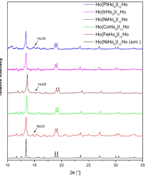
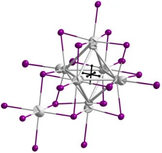
Even though stoichiometric amounts of all reactants were used, only Ho{CoHo6}I12 and Ho{IrHo6}I12 could be obtained as pure phases according to X-ray powder diffrac- tion data (Fig. 3.5). Based on its considerably large thermodynamic stability, HoOI is formed as a byproduct once small oxygen impurities are involved in the reaction process.
They can either result from impurities in the reactants or more likely from diffusion of oxygen from the silica tube through the walls of the tantalum ampoule which is increased by applying longer reaction times at higher temperatures. Also HoI3occured as a byprod- uct, especially in the first attempts of synthesizing Ho{IrHo6}I12, but its formation could be suppressed by using an excess of holmium metal in the form of a metal chunk instead of metal powder.
Figure 3.5.: Powder XRD data of Ho{ZHo6}I12with Z = Fe, Co, Ni, Ir, Pt in comparison with the simulated data of Ho{NiHo6}I12. Impurities of HoOI are present in the Fe, Ni and Pt species.
Syntheses of Ho {ZHo
6} I
12with Z = Fe, Co, Ni, Ir, Pt
The compounds were synthesized using 200 mg HoI3, 46 mg holmium powder and 4 mg iron (cobalt, nickel, 14 mg iridium and platinum) powder. In the case of the iridium analog
to the reaction 4 HoI3+3 Ho+Z→Ho{ZHo6}I12. The reaction mixtures were loaded into tantalum containers and exposed to the following temperature program:
RT50
◦C/h
−→ 800◦C15
◦C/h
−→ 950◦C(200 h)2
◦C/h
−→ 680◦C50
◦C/h
−→ RT
The products consisted of black square prismatic single crystals with edge lengths of 0.1-0.3 mm for the iron, nickel and platinum species and black powder in the case of the cobalt and iridium analogs. Traces of HoOI impurities were detected in the product of the iron, nickel and platinum species whereas Ho{CoHo6}I12and Ho{IrHo6}I12seem to be pure in terms of X-ray powder diffraction (Fig. 3.5).
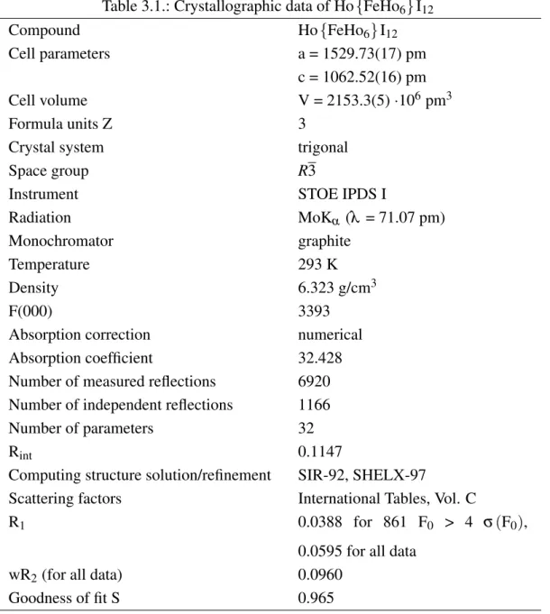
Table 3.1.: Crystallographic data of Ho{FeHo6}I12
Compound Ho{FeHo6}I12
Cell parameters a = 1529.73(17) pm
c = 1062.52(16) pm
Cell volume V = 2153.3(5)·106pm3
Formula units Z 3
Crystal system trigonal
Space group R3
Instrument STOE IPDS I
Radiation MoKα (λ = 71.07 pm)
Monochromator graphite
Temperature 293 K
Density 6.323 g/cm3
F(000) 3393
Absorption correction numerical
Absorption coefficient 32.428
Number of measured reflections 6920 Number of independent reflections 1166
Number of parameters 32
Rint 0.1147
Computing structure solution/refinement SIR-92, SHELX-97
Scattering factors International Tables, Vol. C
R1 0.0388 for 861 F0 > 4 σ(F0),
0.0595 for all data
wR2(for all data) 0.0960
Goodness of fit S 0.965
Table 3.2.: Selected distances in Ho{FeHo6}I12
Atom 1 Atom 2 Distance/pm Atom 1 Atom 2 Distance/pm
Ho1 Ho1 372.97(12) Ho1 I4 311.44(11)
Ho1 Ho1 363.94(11) Ho1 I4 307.22(11)
Ho1 I4 331.16(11) Ho2 I3 301.06(9)
Ho1 I3 317.58(11) Ho1 Fe5 260.56(7)
Ho1 I3 315.65(11)
Table 3.3.: Crystallographic data of Ho{NiHo6}I12
Compound Ho{NiHo6}I12
Cell parameters a = 1530.50(18) pm
c = 1074.28(17) pm
Cell volume V = 2179.3(5)·106pm3
Formula units Z 3
Crystal system trigonal
Space group R3
Instrument STOE IPDS I
Radiation MoKα (λ = 71.07 pm)
Monochromator graphite
Temperature 293 K
Density 6.254 g/cm3
F(000) 3399
Absorption correction numerical
Absorption coefficient 32.189
Number of measured reflections 9768 Number of independent reflections 1348
Number of parameters 32
Rint 0.1016
Computing structure solution/refinement SIR-92, SHELX-97
Scattering factors International Tables, Vol. C
R1 0.0282 for 1270 F0 > 4 σ(F0),
0.0308 for all data
wR2(for all data) 0.0799
Goodness of fit S 1.209
Table 3.4.: Selected distances in Ho{NiHo6}I12
Atom 1 Atom 2 Distance/pm Atom 1 Atom 2 Distance/pm
Ho1 Ho1 374.73(7) Ho1 I4 312.82(6)
Ho1 Ho1 370.44(7) Ho1 I4 310.62(6)
Ho1 I5 329.35(7) Ho1 I5 308.08(6)
Ho1 I5 313.91(7) Ho1 Ni3 263.46(4)
Ho2 I4 313.71(6)
Table 3.5.: Crystallographic data of Ho{PtHo6}I12
Compound Ho{PtHo6}I12
Cell parameters a = 1541.0(3) pm
c = 1078.33(18) pm
Cell volume V = 2217.7(7)·106pm3
Formula units Z 3
Crystal system trigonal
Space group R3
Instrument STOE IPDS I
Radiation MoKα (λ = 71.07 pm)
Monochromator graphite
Temperature 293 K
Density 6.452 g/cm3
F(000) 3549
Absorption correction numerical
Absorption coefficient 35.721
Number of measured reflections 6957 Number of independent reflections 1180
Number of parameters 33
Rint 0.1400
Computing structure solution/refinement SIR-92, SHELX-97
Scattering factors International Tables, Vol. C
R1 0.0505 for 767 F0 > 4 σ(F0),
0.0906 for all data
wR2(for all data) 0.1019
Goodness of fit S 0.919
Table 3.6.: Selected distances in Ho{PtHo6}I12
Atom 1 Atom 2 Distance/pm Atom 1 Atom 2 Distance/pm
Ho1 Ho1 384.95(17) Ho2 I3 313.77(15)
Ho1 Ho1 381.60(16) Ho1 I3 311.89(18)
Ho1 I4 325.66(18) Ho1 I4 309.25(19)
Ho1 I4 315.46(18) Ho1 Pt5 271.02(10)
Ho1 I3 314.27(18)
3.3. Crystal structure of Dy {(C
2)Dy
6} I
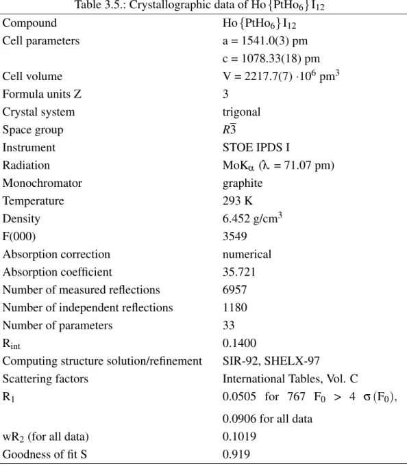
12Going to the element next to holmium, i.e. dysprosium, one would expect similar clusters since the atomic radii and physical properties of both elements differ just marginally. In addition, the electronic structure is quite similar, just varying in onef-electron. However, numerous attempts to synthesize analogous dysprosium clusters with endohedral transi- tion metals failed. But the inclusion of carbon as interstitial succeeded instead, resulting in the compound Dy{(C2)Dy6}I12. As well as the holmium analogs, Dy{(C2)Dy6}I12 crystallizes in the space groupR3 with the lattice constants a = 1523.3(3) pm, c = 1064.9(3) pm and V = 2140.0(7)·106pm3. Other crystallographic parameters can be found in Tab.
3.7, selected distances are listed in Tab. 3.8. The most distinctive feature in comparison with other 7-12 cluster complexes is the encapsulation of a C2unit in contrast to the com- mon single atom. This leads to an elongation of 92.63 pm along the pseudo fourfold axis of the trigonal anti-prismatic dysprosium cluster (Fig. 3.6).
Figure 3.6.: Elongation of the dysprosium cluster along the pseudo fourfold axis in Dy{(C2)Dy6}I12.
As a consequence, it is more appropriate to refer to the cluster as a trigonal anti-prism instead of a distorted octahedron. The Dy-Dy distances vary between 333.13(6) and 373.06(7) pm. The shortest interactions are those building up the central rectangular plane with values of 333.13(6) and 337.85(5) pm whereas the Dy-Dy interactions along the elongation direction reveal larger values, namely 366.32(6), 368.03(3), 371.38(5) and 373.06(7) pm (Fig. 3.7). The latter are similar to those in Ho{FeHo6}I12, constituting a comparable extension of a C2unit along the bond axis as a 3dmetal. However, the shorter
Dy-Dy distances are due to a minor lateral extension of the C2unit due to the small size of a carbon atom. The C-C distance of 149.96(2) pm is slightly shorter than a usual C-C single bond.
Figure 3.7.: Dy-Dy distances in Dy{(C2)Dy6}I12(in pm).
Even though condensed rare-earth halide clusters with C or C2 as interstitials are al- ready known as they can be found in {(C2)Sc6}I11 or {(C2)Sc4}I6 [44] for instance, Dy{(C2)Dy6}I12is the first ternary, monomeric compound with an endohedral C2dumb- bell. Since the C2dumbbells can be orientated parallel to each of the three fourfold axes of a regular octahedron, they appear to be statistically disordered in the same way with a site occupation factor of 1/3 for each C atom. As a result, the dysprosium octahedra undergo an elongation parallel to the C2 units as mentioned above. Consequently, they reveal a corresponding motif of disorder to the interstitials (Fig. 3.8).
On the other hand, neither the DyI6 units nor the bonded iodine atoms seem to be affected by this disorder as apparent in the quite common displacement ellipsoids Fig.
3.9.
Figure 3.8.: Disordered C2dumbbells and Dy atoms in Dy{(C2)Dy6}I12.
Figure 3.9.: Displacement ellipsoids in Dy{(C2)Dy6}I12 drawn at the 90 % probability level.
Synthesis of Dy {(C
2)Dy
6} I
12Dy{(C2)Dy6}I12 was synthesized using 200 mg DyI3, 30 mg dysprosium powder, 6 mg cobalt powder and 4 mg graphite powder. It was actually aimed to get a mixed Co/C2dys- prosium halide. The reaction mixture was loaded into a tantalum container and exposed to the following temperature program:
RT15
◦C/h
−→ 1000◦C(300 h)2
◦C/h
−→ 600◦C50
◦C/h
−→ RT
The product consisted of black square prismatic single crystals with edge lengths of 0.1-0.3 mm which were embedded in a large amount of DyOI.
Table 3.7.: Crystallographic data of Dy{(C2)Dy6}I12
Compound Dy{(C2)Dy6}I12
Cell parameters a = 1523.3(3) pm
c = 1064.9(3) pm
Cell volume V = 2140.0(7)·106pm3
Formula units Z 3
Crystal system trigonal
Space group R3
Instrument STOE IPDS I
Radiation MoKα (λ = 71.07 pm)
Monochromator graphite
Temperature 293 K
Density 6.249 g/cm3
F(000) 3330
Absorption correction numerical
Absorption coefficient 31.064
Number of measured reflections 6805 Number of independent reflections 1142
Number of parameters 45
Rint 0.0792
Computing structure solution/refinement SIR-92, SHELX-97
Scattering factors International Tables, Vol. C
R1 0.0435 for 868 F0 > 4 σ(F0),
0.0624 for all data
wR2(for all data) 0.1088
Goodness of fit S 1.013
Table 3.8.: Selected distances in Dy{(C2)Dy6}I12
Atom 1 Atom 2 Distance/pm Atom 1 Atom 2 Distance/pm
Dy1A Dy1B 373.06(7) Dy3 I4 313.80(4)
Dy1A Dy1B 371.38(5) Dy1B I2 311.93(4)
Dy1A Dy1B 368.03(6) Dy1A I4 310.04(5)
Dy1A Dy1B 366.32(6) Dy1B I2 303.76(4)
Dy1A Dy1A 337.85(5) C C 149.96(2)
Dy1A Dy1A 333.13(6)
3.4. Crystal structure of Dy {CoDy
4.53Y
1.47} I
12Although dysprosium clusters incorporating transition metals are unknown so far, a mixed Dy/Y cluster could be synthesized. The choice of yttrium as co-reactant is due to the simi- lar atomic radius as dysprosium on the one hand and its notably less electrons on the other hand, making it crystallographically distinguishable from dysprosium. The calculated for- mula from crystallographic data is Dy{CoDy4.53Y1.47}I12. The stoichiometric values are well consistent with EDX measurements. As expected, Dy{CoDy4.53Y1.47}I12 crystal- lizes in the space groupR3 with the cell parameters a = 1535.80(18)pm, c = 1078.83(18) pm and V = 2203.7(5)·106pm3. Other crystallographic parameters can be found in Tab.
3.9, selected distances are listed in Tab. 3.10. The cell axes are unusually large com- pared to those of the holmium 7-12 clusters as dysprosium is just marginally larger than the neighboring holmium. The crystallographic calculations reveal that only the clus- ter metal atoms are affected by a partial Dy → Y substitution whereas the MI6 units contain exclusively dysprosium atoms. The cluster metal-metal distances range from 375.54(13) to 378.31(10) pm, the cluster metal-iodine distances vary between 309.00(17) and 314.43(12) pm for bridging iodine atoms and 329.51(12) pm for terminal iodine atoms (Fig. 3.10). The Dy-I distances in the DyI6 entities are 315.04(9) pm and thus quite similar to those in Ho{NiHo6}I12.
Figure 3.10.: Interatomic distances in Dy{CoDy4.53Y1.47}I12 (in pm).
The reason why it has failed to synthesize dysprosium clusters with transition met- als so far could possibly result from electronic circumstances, although Hughbanks and Corbett discuss the responsibility of the competing phase DyI2 for the missing dyspro- sium clusters with transition metals as interstitials [14]. Even if large amounts of DyI2
accumulate during the attempts of synthesizing such dysprosium clusters, the existence of Dy{(C2)Dy6}I12 illustrates that cluster phases can suppress the formation of DyI2. Additionally, it is remarkable that in Dy{CoDy4.53Y1.47}I12, the Y atoms occupy cluster positions instead of MI6 positions, emphasizing that it is probably necessary to stabilize a dysprosium cluster with introducing one to two Y atoms if it encapsulates a transition metal.
Synthesis of Dy {CoDy
4.53Y
1.47} I
12Dy{CoDy4.53Y1.47}I12 was synthesized using 300 mg DyI3, 45 mg dysprosium pow- der, 12 mg yttrium powder and 8 mg cobalt powder according to the attempted reaction 4 DyI3+2 Dy+Co+Y→Y{CoDy6}I12. The reaction mixture was loaded into a tan- talum container and exposed to the following temperature program:
RT50
◦C/h
−→ 800◦C15
◦C/h
−→ 900◦C(300 h)2
◦C/h
−→ 700◦C50
◦C/h
−→ RT
tals. The crystallographically calculated formula Dy{CoDy4.53Y1.47}I12 was confirmed by EDX measurements.
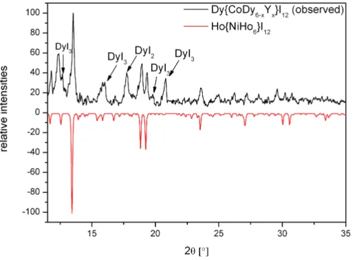
Another attempt to synthesize a mixed Dy/Y 7-12 type cluster, using the same stoichio- metric amounts of the reactants, resulted in a black powder with a 7-12 type compound as main phase and some amounts of DyI2as well as unreacted DyI3(Fig. 3.11).
Figure 3.11.: Powder diffraction diagram of a 7-12 type compound containing Dy and/or Y as cluster building rare-earth metals.
Table 3.9.: Crystallographic data of Dy{CoDy4.53Y1.47}I12
Compound Dy{CoDy4.53Y1.47}I12
Cell parameters a = 1535.80(18) pm
c = 1078.83(18) pm
Cell volume V = 2203.7(5)·106pm3
Formula units Z 3
Crystal system trigonal
Space group R3
Instrument STOE IPDS I
Radiation MoKα (λ = 71.07 pm)
Monochromator graphite
Temperature 293 K
Density 6.214 g/cm3
F(000) 3414
Absorption correction numerical
Absorption coefficient 31.357
Number of measured reflections 7067 Number of independent reflections 1194
Number of parameters 35
Rint 0.1043
Computing structure solution/refinement SIR-92, SHELX-97
Scattering factors International Tables, Vol. C
R1 0.0451 for 837 F0 > 4 σ(F0),
0.0706 for all data
wR2(for all data) 0.1173
Goodness of fit S 0.944
Table 3.10.: Selected distances in Dy{CoDy4.53Y1.47}I12
Atom 1 Atom 2 Distance/pm Atom 1 Atom 2 Distance/pm Dy1|Y1 Dy1|Y1 378.31(10) Dy1|Y1 I4 312.93(12) Dy1|Y1 Dy1|Y1 375.54(13) Dy1|Y1 I4 310.66(12)
Dy1|Y1 I3 329.51(12) Dy1|Y1 I3 309.00(17)
Dy2 I4 315.04(10) Co5 Dy1|Y1 266.53(8)
Dy1|Y1 I3 314.43(12)
3.5. Electronic structure of M {ZM
6} X
12type compounds
The stabilizing role of the interstitial in bonding within rare-earth metal and zirconium clusters has been investigated before on the basis of extended Hückel molecular orbital (EHMO) calculations [14, 22, 48–56]. For 3dmetals the involved orbitals are described in Fig. 3.12. The cluster metal’s d-orbitals contribute largely to the strongly bonding orbitals a1g and t2g, interacting with the interstitial’s 4s and 3d orbitals whereas the t1u and a2uhave no effect on Z-M bonding and thus just contributing on the M6I12unit, even though the former shows cluster bonding. The eg orbital is rather non-bonding and lo- cated on the interstitial. 18 electrons are needed to fill the bonding cluster orbitals (above the lower lying iodine and M-I bonding orbitals). This magical number 18 is realized in Ho{CoHo6}I12 (7·3−12·1+9=18) for instance. Despite the fact that this number seems to be very important in Zr clusters, rare-earth metal clusters do not strictly obey this 18 electron rule; examples with fewer or even more electrons (like in Ho{NiHo6}I12) are widely known. This eminent difference between zirconium and rare-earth metal clusters could be due to the higher lying atomic orbitals of the more electropositive rare-earth el- ements [14].
The situation for compounds with a main group element as interstitial is somewhat different. Thesandpvalence orbitals of the interstitial interact with the cluster’s a1gand t1ulevels and lower them accordingly. The corresponding a∗1gand t∗1ulevels are very high- lying and thus not capable of electron accommodation. As a result, the HOMO – LUMO separation is constituted by the t2g level as the HOMO and the a2u level as the LUMO, adding up 14 electrons to the HOMO – LUMO boundary.
Figure 3.12.: Relative energy levels of molecular orbitals of M6X12 clusters with intersti- tial main group element [22] (left) and transition metal [14] (right).
Despite the long history of 7-12 rare-earth cluster compounds, calculations of the ex- tended structure on the basis of DOS and COHP curves have not been performed. In Figs.
3.13 and 3.14 the DOS and COHP curves of Ho{CoHo6}I12are shown.
Figure 3.13.: Projected DOS of Ho{CoHo6}I12.
Figure 3.14.: COHP curves of Ho{CoHo6}I12.
The COHP curves are of particular interest concerning the bonding situation. Beside the low-lying, rather ionic, bonding Ho-I interactions, bonding Ho-Co interactions occur below the Fermi level. In contrast to that, there are only small bonding interactions be- tween Ho and Ho below the Fermi level, but additional ones above the Fermi level, i.e.
representing empty states whereas all bonding Ho-Co states are below the Fermi level.
This leads to the conclusion that the cluster formation is predominantly assigned by Ho- Co, or in general Ho-Z, instead of Ho-Ho bonding. On the basis of the projected DOS curves, the character of the corresponding orbitals that interact can be determined. The Co 3dstates are located at energies around -2 eV and responsible for the Ho-Co interactions in this region. The stronger Ho-Co interactions right below the Fermi level are widely formed by Co 4pand Ho 5dorbitals.
The Fermi level is located just above the bonding Ho-Ho and Ho-Co and anti-bonding Ho-I interactions beginning at -1 eV and followed by a band gap of 0.7 eV constituting a semi-conductor. According to the EHMO calculations mentioned above, the “magical”
electron number of 18 is realized in Ho{CoHo6}I12. And also in the extended struc-
ture calculations, the electronic situation in Ho{CoHo6}I12 is particularly interesting as the Fermi level exactly separates the bonding Ho-Co interactions from the correspond- ing anti-bonding ones. The situations in the electron-poorer Ho{FeHo6}I12 and richer Ho{NiHo6}I12 are shown in Figs. 3.15 and 3.16. The Fermi level in Ho{FeHo6}I12 is shifted towards the bonding Ho-Ho and Ho-Fe as well as slightly anti-bonding Ho-I states, i.e. in contrast to Ho{CoHo6}I12, it is not possible to fill all the bonding Ho-Z states. The situation in Ho{NiHo6}I12 is exactly the opposite: The higher electron num- ber shifts the Fermi level towards anti-bonding Ho-I states, i.e. leading to a somewhat more unstable structure. These facts resemble the results of the EHMO calculations.
Figure 3.15.: COHP curves of Ho{FeHo6}I12.
The only illogicality in the latter compounds is that the Fermi levels in the correspond- ing DOS curves lie at DOS being unequal to zero, i.e. those compounds actually must be conductors which is not true for monomeric compounds like 7-12 type clusters. This
reveals a band gap at the Fermi level for both, theα andβ electrons.
Figure 3.16.: COHP curves of Ho{NiHo6}I12.
Figure 3.17.: Spin-polarized DOS curves of Ho{NiHo6}I12.
4. Dimeric rare-earth clusters
The first step of cluster condensation leads to bi-octahedral units as realized in the closely related structure types{(C2)2M10}X18,{(C2)2M10}X17and{(C2)2M10}X16. The struc- tural motif consists of two metal octahedra condensed via a common edge forming dimeric clusters. Both octahedra are centered by a C2 unit with the free edges bridged by halo- gen atoms as it is present in the M6X12-type cluster complexes and the vertices bonded to terminal halogen atoms. In this dissertation, two new {(C2)2M10}X18-type com- pounds have been synthesized, namely {(C2)2Dy10}Br18 and {(C2)2Er10}I18, as well as{(C2)2Dy10}I18, recently published by Simon and co-workers [24].
4.1. Crystal structure of {(C
2)
2Dy
10} Br
18{(C2)2Dy10}Br18 crystallizes in the monoclinic space group P21/c with the cell para- meters a = 973.99(12) pm, b = 1633.98(15) pm, c = 1324.69(19) pm, β=120.87(1)◦ and V = 1809.6(4)·106pm3. Other crystallographic parameters can be found in Tab. 4.1, selected distances are listed in Tab. 4.2. As in Dy{(C2)Dy6}I12, the C2 units cause a tetragonal distortion of the octahedron. Therefore, the Dy-Dy distances are quite large along this direction (363.09(7) pm - 403.69(12) pm) whereas the distances perpendicular to the elongation are considerably smaller. In addition, the latter can be distinguished in Dy-Dy bonds forming common edges and those just bridged by bromine atoms. The former are remarkably smaller, exhibiting a bond length of 318.32(11) pm in contrast to the latter with values of 349.38(8) - 355.58(9) pm (Fig. 4.1). Another striking fact is that both octahedra are slightly tilted away from each other (Fig. 4.2), probably to minimize
sium atoms of each octahedron is 419.33(9) pm, hence no real interaction is established between these atoms. The C-C distance is 143.7(13) pm, approximately corresponding to the values in other{(C2)2M10}X18-type compounds [22].
Figure 4.1.: Dy-Dy and selected Dy-Br distances in{(C2)2Dy10}Br18 (in pm).
Figure 4.2.: Lateral view of a dimeric dysprosium cluster in{(C2)2Dy10}Br18 (distances in pm).
The metal atoms are surrounded by bromine atoms above the cluster edges and vertices according to the formulation{(C2)2Dy10}Bri10Bri−a8/2Bra−i8/2, i.e. some of them belong to a single cluster unit while others connect neighboring cluster units, leading to a three- dimensional network (Fig. 4.3). In contrast to{(C2)2Gd10}Cl17 [57],{(C2)2Gd10}Cl16
or{(C2)2Gd10}Cl15 [58], in which neighboring clusters are additionally aligned via i-i contacts,{(C2)2Dy10}Br18 only reveals i-a and a-i contacts, respectively. The structure consists of nine crystallographically inequivalent bromine atoms. Four of them are ter- minal ligands with Dy-Br distances between 294.88(12) and 308.12(12) pm (Fig. 4.1).
It is notable that the Dy-Br distances parallel to the elongation are the shortest ones.
The distances to the edge-capping bromine atoms range from 271.57(15) to 293.40(12) pm. Additionally, the clusters are bridged by another type of bromine atom, connecting the apical dysprosium atoms as well as one of the metal atoms of the common edge of the condensed clusters. The latter Dy-Br bonds exhibit relatively large bond lengths of 296.30(12)) and 332.21(12) pm.
Figure 4.3.: Unit cell of{(C2)2Dy10}Br18.
Synthesis of {(C
2)
2Dy
10} Br
18{(C2)2Dy10}Br18 was synthesized using 150 mg DyBr3, 85 mg dysprosium powder and 8 mg graphite powder, actually in order to synthesize a more condensed phase according
![Figure 2.4.: Scheme of the synthesis of lanthanide(III) bromides and chlorides [30].](https://thumb-eu.123doks.com/thumbv2/1library_info/3647531.1503108/18.892.229.662.134.487/figure-scheme-synthesis-lanthanide-iii-bromides-chlorides.webp)