Hole-spin dynamics and hole g-factor anisotropy in coupled quantum well systems
C. Gradl,1M. Kempf,1D. Schuh,1D. Bougeard,1R. Winkler,2C. Sch¨uller,1and T. Korn1,*
1Institut f¨ur Experimentelle und Angewandte Physik, Universit¨at Regensburg, D-93040 Regensburg, Germany
2Department of Physics, Northern Illinois University, DeKalb, Illinois 60115, USA
(Received 12 August 2014; revised manuscript received 13 October 2014; published 30 October 2014) Due to itsp-like character, the valence band in GaAs-based heterostructures offers rich and complex spin- dependent phenomena. One manifestation is the large anisotropy of Zeeman spin splitting. Using undoped, coupled quantum wells (QWs), we examine this anisotropy by comparing the hole-spin dynamics for high- and low-symmetry crystallographic orientations of the QWs. We directly measure the holegfactor via time-resolved Kerr rotation, and for the low-symmetry crystallographic orientations (110) and (113a), we observe a large in-plane anisotropy of the holegfactor, in good agreement with our theoretical calculations. Using resonant spin amplification, we also observe an anisotropy of the hole-spindephasingin the (110)-grown structure, indicating that crystal symmetry may be used to control hole-spin dynamics.
DOI:10.1103/PhysRevB.90.165439 PACS number(s): 78.67.De,78.55.Cr,78.47.D− I. INTRODUCTION
In recent years, spin dynamics in low-dimensional semi- conductor structures, such as quantum wells (QWs) and quantum dots, has attracted significant scientific interest.
A large number of studies have been conducted on two- dimensional electron systems (2DESs) confined in QWs, exploiting the symmetry of the spin-orbit fields to control electron-spin dynamics. Here, the choice of growth-axis sym- metry allows for suppression of spin dephasing for particular spin orientations in (110)-grown QWs [1–4], cancellation of Rashba and Dresselhaus spin-orbit fields in (111)-grown structures [5,6], or the formation of a persistent spin helix state in (001)-grown QWs [7–9]. Similar studies using these crystallographic degrees of freedom for two-dimensional hole systems (2DHSs) are lacking, even though large anisotropies of theg factor [10,11] and suppression of hole-spin dephas- ing [12] have been predicted. This is, in part, due to the diffi- culties associated withp-modulation doping, which requires different growth strategies depending on the crystallographic orientation of a 2DHS [13–15]. Conventional undoped QWs are not suitable for low-temperature spin dynamics studies, as rapid photocarrier recombination limits the observation window for optically oriented carriers to less than 100 ps. The complex structure of the valence band also complicates studies of hole-spin coherence: In GaAs-based structures, long-lived hole-spin coherence can only be expected if the degeneracy between light-hole (LH) and heavy-hole (HH) bands that is present in the bulk [16] is lifted by confinement. Yet even in confined systems, there is a pronounced mixing of LH and HH bands for wave vectorsk >0 [17]. Thus, long-lived hole-spin coherence is only observed for low-density 2DHSs at low temperatures [18–20]. In these conditions, hole-spin dephasing times may rival or even exceed those of conduction-band electrons due to the reduced hyperfine interaction of thep-like holes with surrounding nuclei [21,22].
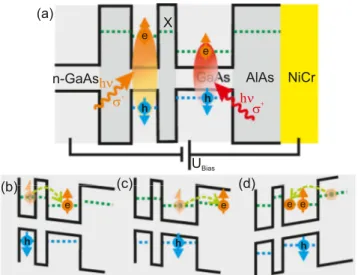
To address these challenges, we utilize a special sample design, which is sketched in Fig. 1(a). It consists of an undopeddouble QW structure with an AlAs barrier separating
*tobias.korn@physik.uni-regensburg.de
a wide and a narrow QW. The states in the X valley of the AlAs barriers are energetically close to the electron states in the narrow QW, so that fast electron tunneling is possible [23]. Application of a bias voltage between a back contact and a semitransparent top gate allows tilting of the QW.
By resonant optical excitation, spin-polarized electron-hole pairs can selectively be created in the narrow or the wide QW. Figure 1(b) depicts resonant excitation of the narrow QW. Optically oriented electrons rapidly tunnel from the narrow QW into the wide QW, while the holes remain in the narrow QW. This spatial separation of the optically oriented electron-hole pairs leads to photocarrier lifetimes of the order of several μs [23], well above the spin dephasing times.
The AlAs barrier thickness of 8 nm precludes the formation of interwell excitons, so that excitonic effects on the spin dynamics [24] may be neglected. By resonant excitation of the wide QW, two different regimes are accessible: Depending on the gate bias, additional electrons may tunnel into the QW, or some of the optically oriented electrons may tunnel out, as indicated in Figs.1(c)and1(d), creating an imbalance between electron and hole concentrations. After direct photocarrier recombination in the QW, which occurs on a 100 ps time scale, excess spin-polarized carriers remain in the QW, and their spin precession in an in-plane magnetic field can be observed on a nanosecond time scale.
In the following, we present time-resolved studies of the spin dynamics for electrons and holes confined in double QW structures grown along different crystallographic orientations.
Three samples, grown on (001) (sample A), (110) (B), and (113a) (C) substrates, are investigated. We demonstrate gate control of the dominant charge carrier type in the QW, and are able to observe long-lived hole-spin precession in all samples. The (001)-grown sample serves as a reference to compare hole-spin dynamics in our undoped double QW structure to previous results obtained onp-modulation-doped, (001)-grown samples [19,20,25,26]. For the (113a)- and (110)-grown samples, we find a large magnitude, and a pronounced in-plane anisotropy of the holegfactor, in good agreement with our theoretical calculations, and a weaker anisotropy of the electron g factor. In the (110)-grown sample, we additionally observe an anisotropy of the hole-spin dephasing.
FIG. 1. (Color online) (a) Sample structure. Spin-polarized electron-hole pairs can be created by resonant optical excitation in the narrow or the wide QW. The states in theXvalley of the AlAs barrier layers are energetically close to the electron states in the narrow QW.
(b) After resonant excitation in the narrow QW, electrons can rapidly tunnel into the AlAs barrier if the QW is tilted by the gate bias, so that only holes remain in the QW. (c), (d) Depending on the bias, after resonant excitation in the wide QW, either electrons tunnel out of the QW, or additional electrons tunnel into the QW from the top contact.
II. SAMPLE STRUCTURE AND EXPERIMENTAL METHODS
A. Sample design
All samples were grown by molecular beam epitaxy (MBE) on undoped wafers with different crystallographic orientations [sample A: (001); B: (110); C: (113a)]. The active region consists of two GaAs QWs embedded in AlAs barriers, following a design introduced in Ref. [23]. A highlyn-doped bulk GaAs layer is grown below the active region to serve as a back contact. This layer is contacted from the top by alloying indium contacts. The QWs have nominal widths of 5 nm (narrow QW) and 12 nm (wide QW), respectively, and are separated by an 8 nm wide AlAs barrier. A semitransparent top gate was prepared on the samples. For this, a 10 nm thick SiO2 layer, followed by a semitransparent, 6 nm thick NiCr layer, were thermally evaporated on top of the sample.
B. Optical spectroscopy
A pulsed Ti-sapphire laser system, generating pulses with 2 ps length, and a corresponding spectral width of 1 meV, was used for the time-resolved Kerr rotation (TRKR) and resonant spin amplification (RSA) measurements. The repetition rate of the laser system is 80 MHz, corresponding to a time delay of 12.5 ns between subsequent pulses. The laser pulses are split into a circularly-polarized pump beam and a linearly-polarized probe beam by a beam splitter. A mechanical delay line is used to create a variable time delay between the pump and probe.
Both beams are focused to a diameter of about 80μm on the sample using an achromatic lens. Excitation densities of about
5 W cm−2 are used for the pump beam, corresponding to an optically induced carrier density of about 1.5×1010cm−2.
Low-temperature measurements were performed in an optical cryostat with an 3He insert where the samples are cooled to about 1.3 K. Magnetic fields of up to 11.5 T can be applied, either in the QW plane or perpendicular to it.
In the TRKR and RSA experiments, the circularly-polarized pump beam is generating electron-hole pairs in the QW, with spins aligned parallel or antiparallel to the beam direction, i.e., the QW normal, depending on the helicity of the light.
In the TRKR measurements, the spin polarization created perpendicular to the sample plane by the pump beam is probed by the time-delayed probe beam via the Kerr effect: The axis of linear polarization of the probe beam is rotated by a small angle, which is proportional to the out-of-plane component of the spin polarization. This small angle is detected using an optical bridge. A lock-in scheme is used to increase sensitivity. The RSA technique is based on the interference of spin polarizations created in a sample by subsequent pump pulses. For certain magnetic fields applied in the sample plane, the optically oriented spin polarization precesses by an integer multiple of 2πin the time window between subsequent pump pulses, so that constructive interference occurs. This leads to pronounced maxima in the Kerr rotation angle, measured for a fixed time delay as a function of the magnetic field.
III. NUMERICAL CALCULATIONS
The numerical calculations of Zeeman spin splitting have been based on the 8×8 Kane Hamiltonian, including the lowest conduction band6cas well as the highest valence band 8v and the spin split-off valence band 7v [17]. The in-plane magnetic fieldB=(Bx,By,0) was taken into account via the vector potentialAusing the asymmetric gaugeA(z)= (zBy,−zBx,0). Diagonalizing the Kane Hamiltonian as a function of the kinetic momentumk+eAthen yields the Zeeman-split energy dispersionsEνσ(k) of the spin subbands ν↑ and ν↓ in the presence of the magnetic field B. This model contains the g factor only implicitly. We extract g for the lowest HH subbandν=0 from the Zeeman splitting E=E0↑(k=0)−E0↓(k=0) calculated atB=1 T using g=E/(μBB), whereμB is the Bohr magneton. We note that the simplified expressions for the anisotropicgpreviously presented in Ref. [10] were based on the smaller, less accurate Luttinger Hamiltonian containing only the highest valence bandv8. The Luttinger model is thus best suited to describe hole systems in wide QWs where the confinement energies are small. The more accurate Kane model used here contains nonparabolic corrections to all orders in the wave vectorkso that it is appropriate also for the more narrow samples studied here. All band-structure parameters entering the Kane model are well known from many independent experiments [17].
Therefore, the calculations presented here can be regarded as parameter free. We neglect for clarity the anisotropic Zeeman term known from the band structure of bulk GaAs, as its prefactor q =0.01 is an order of magnitude smaller than the effects we study here. Numerical algorithms follow Ref. [17].
0.0 0.5 1.0 1.5 2.0 -1 0 1 0.0 0.5 1.0 1.5 0.08-6 -4 0 5 10 15
0.10 0.12 0.14 0.16 0.18 0.20
Gate bias
-3 V (x2) 5 V (x2) 15 V
RSASignal(arb.units)
In-plane magnetic field (T)
16 V 737.5 nm (x2)
736.5 nm
RSAsignal(arb.units)
In-plane magnetic field (T) 730.6 nm (x2) Sample A: narrow QW
Sample A: wide QW
(d) (c)
(a) Gate bias
5 V -1 V
-3 V (x3)
Kerrsignal(arb.units)
Time t (ns) B= 2 T
(b)
e h
|ge|
|gfactor|
Gate bias (V)
|gh|
0.0 0.5 1.0 1.5 2.0 2.5 3.0 3.5 4.0
Spindeph.time(ns)
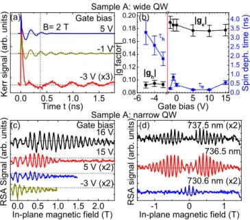
FIG. 2. (Color online) (a) TRKR traces measured on the wide QW in sample A at a fixed in-plane magnetic field of 2 T for different gate biases. (b) Electron and holegfactors and spin dephasing times as a function of gate bias. The vertical line indicates the crossover from a hole- to an electron-dominated regime. (c), (d) RSA measurements on the narrow QW in sample A as a function of (c) gate bias and (d) excitation wavelength.
IV. RESULTS AND DISCUSSION
A. Electron- and hole-spin dynamics in (001)-grown coupled QW system
First, we validate our sample design by performing TRKR measurements on the wide QW of the (001)-grown sample A.
Figure2(a)exemplarily shows three TRKR traces measured for different values of the gate bias with a fixed in-plane mag- netic field of 2 T. All traces show a pronounced peak of the Kerr signal around zero time delay, indicating optical orientation of electron-hole pairs and partial photocarrier recombination within the QW. This is followed by an exponentially damped oscillation, which we identify as the Larmor precession of the optically oriented carriers remaining in the QW. When we compare the two top traces to the bottom trace, we clearly see a large difference in the precession frequencies. We extract the spin precession frequencies and spin dephasing times (SDTs) by fitting an exponentially damped cosine function to TRKR traces measured for a wide range of bias voltages.
Whether the observed spin precession for a certain bias is caused by electrons or holes can be determined via the magnitude of the effectivegfactor. We note that in our TRKR measurements, we cannot determine the sign ofg. The results are summarized in Fig.2(b). For bias voltages above−3 V, we find a nearly constant g-factor value of 0.18, which we assign to electron-spin precession. The AlAs barriers in our structure lead to a stronger confinement than the more common Al0.3Ga0.7As barrier material, so that the e1-hh1 transition energy in our QW, measured in photoluminescence (not shown) is about 1555 meV. In a study of GaAs-AlxGa1−xAs QWs with different Al concentrations, Yugova et al. found
an effective electron g factor of 0.20 for similar transition energies [27], in reasonable agreement with our observations.
As the bias voltage is lowered below−3 V, there is a sharp transition to a smaller g factor of 0.09, which we assign to hole-spin precession. In contrast to previous studies on gatedp-doped GaAs-AlGaAs QWs [19], we do not observe a pronounced dependence of the holegfactor on the gate bias.
This indicates that the hole wave function does not significantly penetrate into the AlAs barriers due to the large barrier height. Therefore, there is no bias-dependent admixture of the respective holegfactors in the QW and barrier materials. We note that the ensemble SDT of the holes is significantly larger than that of the electrons [see Fig.2(b)] and increases with decreasing gate bias. Most likely, the dependence of the hole SDT on the gate bias is caused by a combination of two effects:
First, the tunneling rates of the holes may change with the gate bias, limiting the effective lifetime in the QW. Second, the position of the maximum of the hole wave function within the QW shifts with gate bias, so that thegfactor inhomogeneity may change and influence the ensemble SDT. This effect will be discussed below in more detail. By contrast, the electron SDT does not show a strong dependence on the bias, indicating that the effective lifetime of electrons in the QW is limited by tunneling processes involving theXvalley states in the barriers.
To explore the limits of hole-spin dephasing in our sample, we perform RSA measurements on the narrow QW, as previous studies have shown that the large HH-LH splitting in narrow QWs leads to increased hole SDTs [20]. Figure 2(c)shows RSA traces measured for different gate biases for a laser excitation energy slightly above the resonance of the narrow QW. In a large gate voltage range, optically oriented electrons can rapidly tunnel out of the narrow QW, as indicated in Fig.1(b), so that excess holes remain in the QW. Due to the interplay of hole-spin relaxation, spin-selective photocarrier recombination [25,28], and electron tunneling, we observe RSA maxima also at zero magnetic field, and a sign reversal of the RSA peaks occurs at a finite magnetic field of about 0.2 T. As the magnetic field is increased further, the amplitude of the RSA peaks decays due to hole-spin ensemble dephasing caused by the holeg-factor inhomogeneityg[29]. This leads to a characteristic magnetic-field dependence of the ensemble hole SDT,τh:
τh=
1
T2 +ghμBB
−1
. (1)
Here,T2 is the hole SDT in the absence of magnetic-field- induced dephasing. Remarkably, the decay of the RSA peaks shows a strong dependence on the gate bias: For large positive bias, RSA signals can be observed up to magnetic fields of more than 2 T. To extract T2 and gh from the data, we compare the RSA traces to a rate equation model [20] (see the Appendix). We find aT2 of 10 ns, and a minimumgh
of 0.002. The minimumghfor our double QW structure is below the value previously observed inp-doped QWs [20,30], indicating that the absence of (modulation) doping leads to a significant reduction of local potential fluctuations. A large positive gate bias centers the hole wave function within the narrow QW, so that the effect ofg-factor fluctuations due to interface roughness is minimized as well.
We study the initialization of the hole-spin polarization in more detail by varying the laser excitation energy in the RSA measurements for a fixed gate bias. For near-resonant excitation [the upper trace in Fig. 2(d)], there is only a small RSA peak observable at zero magnetic field, and the RSA amplitude builds with increasing field due to electron- precession-induced initialization of a hole-spin polarization.
As the excitation energy is increased (middle trace), a pro- nounced zero-field RSA peak is observed, which stems from an indirect initialization of the hole-spin polarization. During energy relaxation, most of the optically oriented hole spins relax, while the electron-spin polarization is conserved. In sub- sequent photocarrier recombination, spin-polarized electrons predominantlyremove holes with matching spin orientation, initializing a hole-spin polarization which is oriented in the opposite direction of the optically oriented holes. As the magnetic field is increased, the precession-induced initial- ization becomes dominant, leading to a sign reversal of the RSA peaks. For even larger excitation energy, we observe a pronounced RSA peak at zero field, and finite-field RSA peaks with the same orientation. This shape of the RSA trace can be explained by rapid tunneling of spin-polarized electrons out of the QW, which is facilitated by the excess energy due to nonresonant excitation. Therefore, the optically oriented hole-spin polarization is not depleted by direct photocarrier recombination at zero magnetic field. The RSA signal for these conditions can also be simulated precisely using our rate equation model [see Fig.5(b)]. To summarize, the hole-spin dynamics we observe in our (001)-grown undoped double QW structure is in good agreement with previous results obtained onp-modulation-doped, (001)-grown samples, demonstrating the validity of our sample design. The double QW structure shows a smaller holeg-factor inhomogeneity than modulation- doped samples due to reduced local potential fluctuations.
B. In-plane holeg-factor anisotropy in (110)- and (113a)-grown coupled QW systems
In our study of samples B and C, we mostly focus on TRKR measurements to determine the large holeg-factor values and the in-plane anisotropy predicted for (110)- and (113a)-grown QWs [10]. For both samples, we first determine the gate bias range in which a transition from electron- to hole-dominated long-lived spin precession occurs by determining the effective gfactor. This is shown exemplarily for sample C in Fig.3(a).
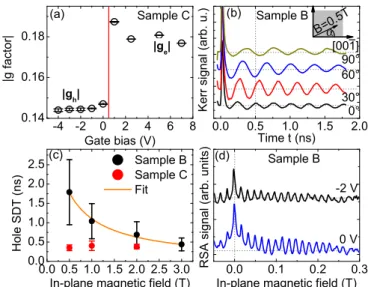
Here, the effective gfactor shows a sharp transition from a value of about 0.18 for positive gate bias, which we assign to electron-spin precession, to a value of about 0.15 as the bias is reduced to 0 V and below, corresponding to hole-spin precession. Then, we perform a series of TRKR measurements with different magnetic fields for a fixed gate bias in the hole-dominated range, with the magnetic field oriented in the QW plane at an angleαrelative to the in-planexaxis. The ef- fective hole g factor is extracted from a linear fit of the magnetic-field-dependent precession frequency. Each sample is manually mounted in four different orientationsαrelative to the magnetic field in subsequent cooling cycles. We clearly see that the precession frequency for a fixed magnetic field drastically changes with the orientation of the field relative to the crystallographic axis, as Fig. 3(b)exemplarily shows
-4 -2 0 2 4 6 8
0.14 0.16 0.18
0.0 0.5 1.0 1.5 2.0 2.5 3.0 0.0
0.5 1.0 1.5 2.0 2.5
0.0 0.1 0.2 0.3 0.0 0.5 1.0 1.5 2.0
|gh|
|ge|
|gfactor| HoleSDT(ns) RSAsignal(arb.units)Kerrsignal(arb.u.)
α B=0.5T
FIG. 3. (Color online) (a) Electron and hole g factors as a function of gate bias in sample C. The vertical line indicates the crossover from a hole- to an electron-dominated regime. (b) TRKR traces measured on sample B for a fixed magnitude of the in-plane magnetic field applied at various anglesαrelative to the [00¯1] axis.
(c) Hole SDTs as a function of in-plane magnetic field for samples B and C. The data are averaged over all in-plane orientations of the samples. The solid line indicates a fit to the data using Eq. (1). (d) RSA measurements on sample B using different gate voltages. The field is applied parallel to the [¯110] axis.
for sample B. This variation is due to the in-plane anisotropy of the holegfactor. In the following we denote the in-plane crystallographic direction [00¯1] ([33¯2]) of sample B (C) as the xaxis and the direction [¯110] as theyaxis [see Fig.4(a)]. For an arbitrary angleαof the in-plane magnetic field relative to thex axis, the effective holegfactorgh∗(α) can be calculated using thegfactorsgxandgy in thexandydirections:
gh∗(α)=
gx2cos2(α)+gy2sin2(α). (2) Thus, we can extract gx andgy by fitting Eq. (2) to gh∗(α) measured for each sample. The results are summarized in TableI.
To obtain an accurate basis for comparison of our exper- imental results, we perform calculations of the HH Zeeman spin splitting as a function of the QW growth axis and the in-plane magnetic-field orientation for a QW width of 12 nm. The coordinate system is sketched in Fig.4(a). The growth axis in the [mmn] direction is rotated with respect to the [001] crystallographic axis by an angleθ, such that the in-plane major directions are [nn(2m)] (x axis) and [¯110]
(y axis). Figure 4(b) shows the hole g factor obtained in these calculations. While g is close to zero for (001)- and (111)-grown QWs, large values (in magnitude) are obtained for (113) and (110) growth, and a pronounced anisotropy for different in-plane magnetic-field orientations is clearly visible.
Remarkably, a significant in-plane anisotropy is obtained here for the narrow 12 nm wide (110)-grown QW, whereas such an anisotropy is absent in previous calculations for wider (110)- grown QWs [10]. By contrast, the gfactor for (113)-grown QWs does not vary strongly with QW width. For sample C,
[100]
[010]
θ [001]
[mmn]
[mmn]z z
[nn(2m)]
x
[110]
y (a)
0 30 60 90
0.35 0.40 0.45 0.50 0.55 0.60
0 30 60 90
-0.6 -0.4 -0.2 0.0 0.2 0.4 0.6 0.8
0 30 60 90
0.1 0.2 0.3 0.4 0.5 0.6 0.7
0.8 Sample C [113]
Sample B [110]
Exp.
Fit Calc.
|gh|
Angle (deg.)
[nn(2m)]
(c)
[111] [110]
[113]
gh*
Angle (deg.) [001]
(b)
[110]
Exp.
Fit Calc.
(d)
|gh|
Angle (deg.)
FIG. 4. (Color online) (a) Schematic of the coordinate system used in the paper. (b) Numerical calculation of the holeg factor for two different in-plane magnetic-field directions as a function of the angle between the growth axis and [001] assuming a QW width of 12 nm. (c), (d) Holegfactor of (c) sample B and (d) sample C as a function of in-plane magnetic-field angleαrelative to the [nn(2m)]
(x) axis. The solid lines in (c) and (d) indicate fits to the data using Eq. (2), and dashed lines indicate values calculated with Eq. (2) using the data depicted in (b).
the calculated values for|gh|as a function of the angleαare in very good agreement with the measured values [Fig.4(d)].
In this sample, the holegfactor changes by a factor of 4 as a function of the angleα. By contrast, we observe a smaller change of|gh|in sample B, and for the in-plane [00¯1] axis, the calculated value of|gh|is slightly smaller than the measured value [see Fig. 4(c)]. The latter may be due to our gated sample structure, which leads to a growth-axis asymmetry of the confining potential, corresponding to a further reduction of the effective QW width. In addition to the large in-plane anisotropy of|gh|, there is also a weaker in-plane anisotropy of the electron g factor in both samples (see Fig. 6). This anisotropy was previously observed in narrow (110)-grown QWs [31]. To summarize, our sample design allows us to directly observe a large in-plane anisotropy of the holegfactor for QWs grown on low-symmetry surfaces. The experimental results are in good agreement with realistic calculations of the HH Zeeman splitting that take the width of our QW structures into account.
TABLE I. Hole g factors for two in-plane crystallographic directions in samples B and C.
Sample Axis |gh|
B [¯110] 0.364±0.003
[00¯1] 0.554±0.008
C [¯110] 0.151±0.007
[33¯2] 0.692±0.008
-0.1 0.0 0.1 0.2
0.0 0.2 1.5 2.0
Sample A
in-plane magnetic field (T)
Sample B in-plane magnetic field (T) (b)
RSA signal simulation
RSAsignal(arbitraryunits)
(a)
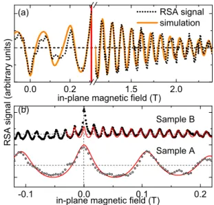
FIG. 5. (Color online) (a) Low- and high-field regions of the RSA trace measured on the narrow QW in sample A for a 16 V gate bias compared to a simulated RSA trace. (b) RSA traces measured on sample B (top trace, dots) and sample A (bottom trace, open circles) compared to simulated RSA traces (solid lines).
C. Hole-spin dephasing anisotropy in (110)-grown coupled QW system
We investigate the magnetic-field dependence of the hole SDT in samples B and C to determine the mechanism limiting hole-spin coherence. For this, we average the hole SDT values measured by TRKR for a certain magnetic field over all magnetic-field orientations. The results are depicted in Fig. 3(c), demonstrating that the two samples show rather different behavior: In sample B, the hole SDT shows a characteristicB−1dependence as described by Eq. (1), indicating that theg-factor inhomogeneity limits the hole SDT in high magnetic fields. By contrast, the hole SDT in sample C is significantly shorter (below 400 ps), and is independent of the magnetic field. In this sample, carrier tunneling and recombination may limit the effective hole SDT. To study the hole SDT in low magnetic fields, we also perform RSA measurements on sample B. Figure3(d)shows RSA traces, measured with the magnetic field applied parallel to the [¯110] axis, for different applied gate voltages in the range where we observe hole-spin dynamics in TRKR. For the gate voltages investigated, we find a pronounced RSA maximum for B=0 T, with all finite-field RSA maxima having the same orientation. This shows that the long-lived hole-spin polarization is initialized directly by the optically oriented holes, while spin-polarized electrons rapidly tunnel out of the QW, so that there is no complex interplay between electron- and hole-spin dynamics. Remarkably, we find that the RSA maximum amplitude for zero magnetic field is about two times larger than that of the first finite-field maximum, while the amplitudes of subsequent finite-field maxima decrease slowly, indicating weak ensemble dephasing. The shape of this RSA trace cannot be described within our rate equation model [see Fig.5(b)]. It may be explained by an orientational anisotropy of the hole-spin dephasing, with a significantly larger hole SDT for spins oriented along the QW normal.
Such an anisotropy was previously observed for electrons in (110)-grown QWs [4]. To our knowledge, the influence of the QW symmetry onhole-spin dephasing has only been considered for (111)-grown QWs, so far [12], and merits further investigation.
V. CONCLUSION
In summary, we have studied spin dynamics in undoped double QW systems. We find that long-lived spin dynamics can be observed in these structures due to a spatial separation of electrons and holes. Gate-dependent measurements demon- strate that either long-lived electron- or hole-spin polarization can be generated in one of the QWs. In resonant spin ampli- fication measurements, we demonstrate hole-spin dephasing times of up to 10 ns and a very low inhomogeneity of the holegfactor. The fact that our structures are undoped allows us to prepare samples grown along different crystallographic orientations. In (110)- and (113a)-grown structures, we find a large in-plane anisotropy of the holegfactor, in agreement with our numerical calculations, and a weaker in-plane anisotropy of the electrongfactor. In the (110)-grown sample, we find indications of anisotropic hole-spin dephasing. Our results may pave the way for future studies on the control of hole-spin dynamics using crystal symmetry engineering.
ACKNOWLEDGMENT
Financial support by the Deutsche Forschungsgemeinschaft (DFG) via Projects No. SPP 1285 and No. SFB 689 is gratefully acknowledged.
APPENDIX
1. Extraction of spin dynamics parameters from RSA traces The characteristic shape of the RSA traces due to hole- spin dynamics has been previously studied in p-doped QWs [20,30]. It arises from the interplay of spin and photocarrier dynamics. Under resonant optical excitation of a QW, oppositely equal electron- and hole-spin polarizations are created, and in the absence of a magnetic field or other processes which would create an imbalance between electron- and hole-spin polarizations, spin-polarized electrons recom- bine with holes that match their spin orientation, so that photocarrier recombination removes the spin polarizations, and no transfer of hole-spin polarization to resident carriers occurs. Therefore, in measurements under these conditions, no RSA peak at zero magnetic field is observed. For finite magnetic fields, which lead to different spin precession frequencies for electrons and holes, some transfer of spin polarization to resident holes occurs, and RSA peaks are observed. Nonresonant excitation leads to a partial dephasing of the optically oriented hole-spin polarization during energy relaxation. During photocarrier recombination, optically ori- ented electrons preferably remove hole spins with matching orientation, so that an excess of hole spins with opposite spin orientation remains in the sample. This is visible as a zero-field RSA peak with orientation opposite to finite-field RSA peaks. The combined dynamics of the electron- and hole-spin polarizations can be described via coupled equations
0.0 0.5 1.0 1.5 0.0
0.2 0.4 0.6 0.8 1.0 1.2 1.4 1.6 1.8 2.0
0 30 60 90 0.10
0.12 0.14 0.16 0.18 0.20
Kerr signal (normalized) |ge|
α
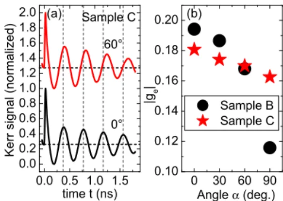
FIG. 6. (Color online) (a) TRKR traces measured on the wide QW in sample C at a fixed magnetic fieldB=1 T for two different in-plane orientations of the field. The vertical lines serve as a guide to the eye. (b) Electrongfactors as a function of in-plane magnetic-field angle for samples B and C.
of motion for the electron- (e) and hole- (h) spin polarization vectors,
de dt = − e
τR +geμB
(B×e),
dh dt = −h
τh
+ghμB
(B×h)+ezz τR
,
withτR being the photocarrier recombination time. Here, the effect of a fast partial hole-spin dephasing during energy relaxation can be modeled by using different initial values for electron- and hole-spin polarizations. To include the effects of ensemble dephasing due tog factor inhomogeneity [29], we utilize the magnetic-field dependence ofτh described by Eq. (1). We apply this model to extract the hole-spin dynamics parameters for the RSA measurements performed on sample A. Figure5(a)shows the best fit to the experimental data for near-resonant excitation and a gate voltage of 16 V [top trace in Fig.2(c)] in the low and high magnetic-field ranges. We find gh=0.051, gh=0.002, andT2=8 ns. The same model may also be used to simulate RSA traces measured on sample A under highly nonresonant excitation conditions, as Fig.5(b) demonstrates. Under these conditions, spin-polarized electrons rapidly tunnel out of the QW, so that we only need to consider hole-spin precession and dephasing. We find gh=0.0527, gh=0.0022, andT2=10 ns. With the same approach, we are able to simulate the RSA traces measured on sample B, with the exception of the zero-field RSA maximum.
2. Electrong-factor anisotropy
We investigate the in-plane anisotropy of the electron g factor in samples B and C by studying spin precession in the wide QW for fixed gate voltages in the range where long-lived electron-spin precession is observable. In both samples, we find a systematic variation of the electrong factor with the in-plane magnetic-field orientation. As Fig. 6 shows, this anisotropy is significantly more pronounced in sample B.
Recently, in a study of undoped, (110)-grown QWs with AlGaAs barriers, a similar in-plane anisotropy of the electron gfactor was observed [31] and shown to originate from the low-symmetry growth orientation (110).
[1] M. Dyakonov and V. Kachorovskii, Sov. Phys. Semicond.20, 110 (1986).
[2] Y. Ohno, R. Terauchi, T. Adachi, F. Matsukura, and H. Ohno, Phys. Rev. Lett.83,4196(1999).
[3] S. D¨ohrmann, D. H¨agele, J. Rudolph, M. Bichler, D. Schuh, and M. Oestreich,Phys. Rev. Lett.93,147405(2004).
[4] M. Griesbeck, M. M. Glazov, E. Y. Sherman, D. Schuh, W. Wegscheider, C. Sch¨uller, and T. Korn,Phys. Rev. B85, 085313(2012).
[5] X. Cartoix`a, D. Z.-Y. Ting, and Y.-C. Chang,Phys. Rev. B71, 045313(2005).
[6] A. Balocchi, Q. H. Duong, P. Renucci, B. L. Liu, C. Fontaine, T. Amand, D. Lagarde, and X. Marie,Phys. Rev. Lett.107, 136604(2011).
[7] B. A. Bernevig, J. Orenstein, and S.-C. Zhang,Phys. Rev. Lett.
97,236601(2006).
[8] D. Koralek, C. P. Weber, J. Orenstein, B. A. Bernevig, S.-C.
Zhang, S. Mack, and D. D. Awschalom,Nature (London)458, 610(2009).
[9] M. P. Walser, C. Reichl, W. Wegscheider, and G. Salis,Nat.
Phys.8,757(2012).
[10] R. Winkler, S. J. Papadakis, E. P. De Poortere, and M. Shayegan, Phys. Rev. Lett.85,4574(2000).
[11] M. Kubisa, K. Ryczko, and J. Misiewicz, Phys. Rev. B 83, 195324(2011).
[12] L. Wang and M. W. Wu,Phys. Rev. B85,235308(2012).
[13] J. J. Heremans, M. B. Santos, K. Hirakawa, and M. Shayegan, J. Appl. Phys.76,1980(1994).
[14] C. Gerl, S. Schmult, H.-P. Tranitz, C. Mitzkus, and W. Wegschei- der,Appl. Phys. Lett.86,252105(2005).
[15] C. Gerl, S. Schmult, U. Wurstbauer, H. Tranitz, C. Mitzkus, and W. Wegscheider,Physica E32,258(2006).
[16] D. J. Hilton and C. L. Tang,Phys. Rev. Lett.89,146601(2002).
[17] R. Winkler,Spin-Orbit Coupling Effects in Two-Dimensional Electron and Hole Systems(Springer, Berlin, 2003).
[18] M. Syperek, D. R. Yakovlev, A. Greilich, J. Misiewicz, M. Bayer, D. Reuter, and A. D. Wieck,Phys. Rev. Lett.99, 187401(2007).
[19] M. Kugler, T. Andlauer, T. Korn, A. Wagner, S. Fehringer, R. Schulz, M. Kubov´a, C. Gerl, D. Schuh, W. Wegscheider, P. Vogl, and C. Sch¨uller,Phys. Rev. B80,035325(2009).
[20] T. Korn, M. Kugler, M. Griesbeck, R. Schulz, A. Wagner, M. Hirmer, C. Gerl, D. Schuh, W. Wegscheider, and C. Sch¨uller, New J. Phys.12,043003(2010).
[21] J. Fischer, W. A. Coish, D. V. Bulaev, and D. Loss,Phys. Rev.
B78,155329(2008).
[22] B. Eble, C. Testelin, P. Desfonds, F. Bernardot, A. Balocchi, T. Amand, A. Miard, A. Lemaˆıtre, X. Marie, and M. Chamarro, Phys. Rev. Lett.102,146601(2009).
[23] P. Dawson and M. J. Godfrey, Phys. Rev. B 68, 115326 (2003).
[24] A. V. Larionov and L. E. Golub,Phys. Rev. B78,033302(2008).
[25] M. Kugler, K. Korzekwa, P. Machnikowski, C. Gradl, S. Furth- meier, M. Griesbeck, M. Hirmer, D. Schuh, W. Wegscheider, T. Kuhn, C. Sch¨uller, and T. Korn,Phys. Rev. B 84, 085327 (2011).
[26] K. Korzekwa, C. Gradl, M. Kugler, S. Furthmeier, M. Griesbeck, M. Hirmer, D. Schuh, W. Wegscheider, T. Kuhn, C. Sch¨uller, T. Korn, and P. Machnikowski,Phys. Rev. B88,155303(2013).
[27] I. A. Yugova, A. Greilich, D. R. Yakovlev, A. A. Kiselev, M. Bayer, V. V. Petrov, Y. K. Dolgikh, D. Reuter, and A. D.
Wieck,Phys. Rev. B75,245302(2007).
[28] M. Studer, M. Hirmer, D. Schuh, W. Wegscheider, K. Ensslin, and G. Salis,Phys. Rev. B84,085328(2011).
[29] D. R. Yakovlev and M. Bayer, inSpin Physics in Semiconduc- tors, edited by M. I. Dyakonov (Springer, Berlin, 2008), p. 135.
[30] T. Korn,Phys. Rep.494,415(2010).
[31] J. H¨ubner, S. Kunz, S. Oertel, D. Schuh, M. Pochwała, H. T.
Duc, J. F¨orstner, T. Meier, and M. Oestreich,Phys. Rev. B84, 041301(2011).