REQUIREMENTS FOR THE WORKFLOW-BASED SUPPORT OF RELEASE MANAGEMENT PROCESSES IN THE AUTOMOTIVE SECTOR
Ulrich Bestfleisch, Joachim Herbst DaimlerChrysler AG Research and Technology Data and Process Management (REI/ID)
P.O. Box 2360 D-89013 Ulm, Germany E-mail: ulrich@bestfleisch.de, joachim.j.herbst@daimlerchrysler.com
Manfred Reichert University of Twente Computer Science Department
Information Systems Group P.O. Box 217
NL-7500 AE Enschede, The Netherlands E-Mail: m.u.reichert@cs.utwente.nl
KEYWORDS
Workflow management, release processes, hierarchical workflows, workflow synchronization
ABSTRACT
One of the challenges the automotive industry currently has to master is the complexity of the electrical/electronic system of a car. One key factor for reaching short product development cycles and high quality in this area are well- defined, properly executed test and release processes.
In this paper we show why workflow management tech- nology is needed to support these processes and how this support should look like. We further confront these requirements with the features of contemporary workflow technology and discuss which extensions become necessary.
INTRODUCTION
In modern cars up to 70 electronic control units (ECU), wired by kilometres of cable, cooperate to realize innovative functions for drivers and passengers. But with growing complexity, product quality has become a serious issue in this domain. In this context the development process plays a key role since its quality is correlated with the resulting product quality. Therefore the automotive industry makes great efforts to improve this process and to provide computerized support for it (Knippel and Schulz 2004).
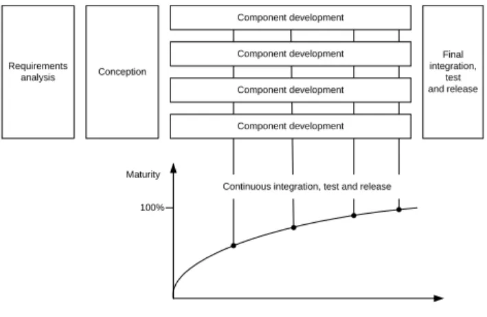
In the development process of the electrical/electronic system (EE-system) of a car one can distinguish four phases (Wehlitz 2000): The requirements analysis and conception phases are followed by the phase during which the different components of the car (e.g. control units and corresponding software) are developed. This is done in parallel and in cooperation with external suppliers. Before producing the car, the components have to be integrated, tested and released. In order to obtain high quality, these steps are continuously repeated during the ongoing development process (cf. Figure 1).
Conception Requirements
analysis
Component development
Component development
Component development
Component development
Maturity
Continuous integration, test and release
Final integration,
test and release
100%
Figure 1: EE-development process according to (Wehlitz 2000) RELEASE OF HIERARCHICAL PRODUCT CONFIGURATIONS
Subject of integration, test and release are (product) configurations which may comprise different versions of components. As a simple example consider the configuration for a particular ECU, which consists of a version of the ECU’s hardware and a version of the ECU’s software.
In our context a configuration expresses a certain degree of compatibility in the sense that components contained in the configuration correctly work together as specified.
Before testing and releasing a configuration this compatibility is assumed by the person who assembles the configuration. After these test and release steps, compatibility is considered as verified such that other activities in the development process can rely on a certain degree of maturity. However, this does not guarantee total correctness since tests only contribute to identify errors but cannot prove their absence.
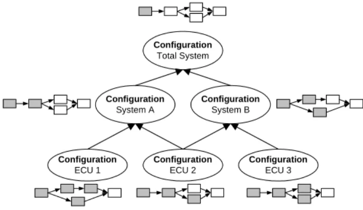
In this context a promising approach is to incrementally assemble hierarchical configurations according to the logical structure of the total EE-system and to integrate the
EE-system in a bottom-up approach (cf. Figure 2). This means that, first of all, configurations are assembled, tested and released at the lowest level. Based on this, further configurations can be assembled from lower level configurations and can be tested and released as well. This is continued until the top of the configuration structure is reached.
Configuration System A
Configuration System B
Configuration ECU 1
Configuration ECU 2
Configuration ECU 3 Configuration
Total System
HW1 v1.1
SW1 v1.4
HW2 v1.0
SW2 v1.3
HW3 v1.7
SW3 v1.1
Figure 2: Example of hierarchical configurations An example is depicted in Figure 2. In this example, the configuration of a single electronic control unit (here consisting of a hardware and a software component in certain versions) constitutes a configuration at the lowest level of the overall configuration. A configuration on a level above could be a system configuration, comprising all ECU configurations for a specific subsystem.
Taking a process-oriented view, each configuration is associated with a release process (cf. Figure 3). The term
“release process” is used for all steps executed in a certain order to ensure compatibility between the components of a configuration. These steps can be real dynamic tests like breadboard-tests or Hardware-in-the-loop-tests. Steps can also be of formal nature like the official approval of the configuration by a committee.
Only if all steps of a release process are executed successfully (i.e., all steps are completed and no errors are found) the respective configuration is considered as correct and can therefore be “released”. By contrast, if errors are found in one or more process steps the configuration is considered as incorrect and can therefore be not released.
If the release processes were executed in a strict sequential order across the different levels of a configuration hierarchy (as described above), this would require a significant long time until the top configuration could be released. For this reason, release processes on different levels are allowed to be executed in parallel. However, in this context certain conditions must be met:
• A configuration on a higher level may only be released after all of its subconfigurations have been released.
• Certain steps of a release process may only be executed after particular steps in the release processes of the corresponding subconfigurations have been executed successfully.
Reason for the latter restriction is that test activities on a higher level are usually more expensive than those on a lower level. Therefore a certain maturity of the lower level configuration has to be reached before steps on an upper level should actually be carried out.
One example for such a dependency between processes at different levels of a hierarchy is the test step of
“flashability” for an ECU: Nowadays many ECUs can be flashed, which means that their software can be replaced arbitrarily often. Testing the flashability of an ECU verifies whether the hardware is able to be flashed in accordance to the rules the automotive manufacturer has specified for the ECU software. On the level of an ECU configuration this test step constitutes the precondition for all dynamic tests on the configuration level above (the systems level). At this level tests cannot be carried out if the software cannot be flashed on the ECUs. This example illustrates just one of many possible inter-process dependencies.
Configuration System A
Configuration System B
Configuration ECU 1
Configuration ECU 2
Configuration ECU 3 Configuration
Total System
Figure 3: Configurations and associated release processes WHY DO WE NEED WORKFLOW-SUPPORT?
In a modern car there are up to 70 ECUs. During development time this results in hundreds of hierarchical configurations, as for each ECU numerous versions for hardware and software exist. Each configuration is associated with a corresponding release process, which does not only coordinate related tasks, but also controls the dependencies to other release processes.
Given these facts it becomes obvious that users need an adequate IT support for coordinating the execution of these processes in terms of workflow management. The main goal for the computerized support of release processes is to ensure their correct execution. In particular, this includes the control and monitoring of their dependencies with other release processes. Manual process coordination and synchronization would be too time-consuming and error- prone in this context. By achieving this main goal workflow support contributes to reach economic goals like cost- reduction and shortening of process cycle times.
VISION OF WORKFLOW SUPPORT
How should an ideal workflow support for the release processes look like? Important requirements are discussed in the following.
1. Starting release workflows for configurations
The person in charge should be able to start a release process for a specific configuration at an arbitrary point in time. However, a release process for a super-configuration may only be started if the release processes of its subconfigurations have already been started or have already been finished successfully.
2. Giving users support to execute test steps
For each step in a release workflow the corresponding actor should have access to the configuration and the test task he must carry out with this configuration. After completion of this task the user should be able to report to the system whether any error was detected or not. The kind of workflow support therefore does primarily not concern the automation of single test steps (e.g., by calling software applications) but the coordination of the release workflow and its synchronization with other release processes. This means tests steps of a release process are thought to be executed outside the scope of the workflow system – only the result of a test step (whether errors were found or not) is reported back to the workflow system. Thus the test steps here are considered to be coarse-grained.
3. Enable flexible reactions to test errors in a particular release process
If one or more errors are found in a configuration the person responsible for this configuration should be notified and be able to decide about further actions. Doing so, he should have the following two options:
• Cancel the workflow as further tests are unnecessary and would not lead to (more) important test results.
• Let the workflow execution continue with the possibility to exclude certain steps from execution.
There may be some steps that produce interesting test results that are important for the ongoing development process, whereas other steps may not do so (like formal approval steps).
4. Set appropriate release state of configuration
After completing a release process the appropriate release state of a configuration should be set. In case at least one error was found the state is set to “not released” otherwise to “released”. This release state can be accessed and viewed by all actors needing access to the configuration during the development process.
Note that a configuration must not obtain the release state
“released” if not all of its subconfigurations own the same state.
5. Consider hierarchical control flow dependencies The various control flow dependencies between release processes of configurations on different levels should be enforced. The release process of a configuration on an upper level may not be continued at a certain point until all release processes of its subconfigurations have reached particular states in their execution.
6. Enable flexible reaction on test errors in sub- and superconfigurations
Assume that errors are found in a configuration during the release process. This has not only consequences for the release process of the directly affected configuration (see Requirement 3) but also for the release processes of sub- and superconfigurations. Like for Requirement 3 the persons responsible for these configurations should be notified. In particular, they should then be able to react in the same flexible way to detected errors in sub- and superconfigurations. As this reaction may depend on the state of the respective release processes of the other configurations they must be able to get a quick status overview of these related processes.
But which configurations (and respectively their release processes) have to be considered when an error is detected for a particular configuration?
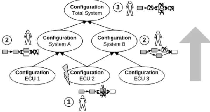
First of all – taking the notion of “bottom-up error- handling” – all superconfigurations have to be considered consecutively to the top (cf. Figure 4). This is required since a configuration may not reach the state “released” if any subconfiguration has not been successfully released.
Therefore, when an error has been detected for a particular configuration, the person responsible for the super- configuration has to decide whether it makes sense to continue (or even start) the corresponding release process although the superconfiguration cannot be released. In addition to Requirement 3 he must also decide which dependencies to other processes are still important and which are not.
Configuration System A
Configuration System B
Configuration ECU 1
Configuration ECU 2
Configuration ECU 3 Configuration
Total System
1
2 2
3
Figure 4: Bottom-up error-handling
Let’s consider the example above: An error was detected, when executing a step in the release process of the configuration ECU 2. At first the corresponding person in charge of this configuration is notified and can make his
decision. In a second step persons in charge for configurations of System A and System B are notified and can react to the situation. Finally the person in charge for the release process of the whole system configuration is notified.
Additionally, when detecting an error in a configuration it is possible that the subconfiguration causing this error can be identified. If the release process of this subconfiguration is still running the responsible person should be notified and have the possibilities as described in the context of Requirement 3. This “top-down error-handling” usually causes additional “bottom-up error-handling” for all of its superconfigurations.
Figure 5 shows an example: An error is detected in the configuration System A. This error can be deduced to an error in the configuration ECU 2. So after reaction to the error of configuration System A the person in charge for ECU 2 is notified and can influence the release process. To maintain consistency the “bottom-up error handling” starts for the System B configuration and afterwards for the total system configuration. (Remark: Since the total system configuration is a super configuration of the System A configuration the error handling for the total configuration would also have been initiated if the top-down error- handling had not been executed.)
Configuration System A
Configuration System B
Configuration ECU 1
Configuration ECU 2
Configuration ECU 3 Configuration
Total System
2
1 3
4
Figure 5: Top-Down and resulting bottom-up error- handling
SPECIAL REQUIREMENTS FOR WORKFLOW- MANAGEMENT-SYSTEMS (WFMS)
Attempts to capture the discussed requirements by means of contemporary workflow management systems have been unsuccessful. In particular, they have revealed the fact that it is not possible to implement these requirements without expensive and cumbersome workarounds – mainly by invoking external applications implementing the above described requirements as a hard-wired black-box. Possible consequences of this approach are high maintenance costs, bad adaptability to organizational changes and new processes, etc..
The following special requirements (not supported by contemporary workflow management systems) can be identified:
• Modelling and enforcing of control flow dependencies between parallel workflows depending on data associated with a workflow.
• Dynamic adaptation of these dependencies at runtime.
• Dynamic deletion of steps from a workflow instance (and its impact to concurrently running workflow instances).
• Built-in-support for special kinds of “error- handling” as described in the context of Requirements 3 and 6. It is important to notice that these errors may not be mistaken for errors as normally considered in the context of workflow management systems (cf. Eder and Liebhart 1995).
In contrast to the common understanding where an error of an activity means a failure in the execution of the activity itself, in our context error denotes a regular result of an activity.
• Features enabling decision makers to get a quick overview of the state of all release processes directly or indirectly associated with a configuration, e.g. in case of test errors and the decision about the further proceeding.
RELATED WORK
In the conventional workflow world hierarchical workflows are understood quite differently. For example, in MQ Series Workflow hierarchical means, that an activity of a workflow can also be implemented as another workflow.
During runtime then another workflow is initiated as a subworkflow for this activity. After completion of the subworkflow the calling workflow continues with its execution (Leymann and Roller 2000). This understanding of hierarchical workflows is also shared, for example, by many workflow execution models like Petri Nets (Aalst and Hee 2002), FunSoft Nets (Deiters and Gruhn 1994), or State- and Activitycharts (Harel 1987).
By contrast, in our case hierarchical means that workflows are executed in parallel with control flow dependencies between them depending on the hierarchical structure of the configurations they are associated with. As discussed this raises a number of requirements with respect to the workflow execution model not covered by today’s approaches.
The synchronization of “real” parallel processes has been subject of some research approaches (e.g. Kamath and Ramamritham 1998, Hagen and Alonso 1999, Heinlein 2001). However, none of them allows to express control flow dependencies based on data associated with a workflow the way it is needed here.
Many research approaches (e.g. Reichert and Dadam 1998, Weske 1998, Casati et al. 1998) are dealing with adaptive workflows. But as far as the authors knowledge concerns,
the issue has not been considered in combination with synchronization of workflows and dynamic adaptation of dependencies between them.
CONCLUSIONS AND OUTLOOK
For a successful implementation of release processes in the electrical/electronic domain it is a necessity to support them by workflow technology. However, the requirements identified for such a support are not met by current workflow technology. Research has already been dealing with main issues here – but in a rather separate and non- integrated approach. So the next step is to develop an integrated, coherent workflow concept for this domain.
REFERENCES
Aalst van der, W., Hee van, K. (2002). Workflow Management, MIT Press, 2002.
Casati, F.; Ceri, S.; Pernici, B.; Pozzi, G. (1998). Workflow Evolution. In: Data & Knowledge Engineering, Vol. 24, No.
3, January 1998, pp. 211-238.
Deiters, W.; Gruhn, V. (1994). The FUNSOFT Net Approach to Software Process Management. In: Int’l Journal of Software Engineering and Knowledge Engineering, Vol. 4, No. 2, 1994, pp. 229–256.
Eder, J.; Liebhart, W. (1995). The Workflow Activity Model WAMO. In: Proc. 3rd Int’l Conf. in Coop. Inf. Systems, Vienna (1995).
Harel, D. (1987). Statecharts: A Visual Formalism for Complex Systems, Science of Computer Programming, Vo. 8, 1987 Hagen, C.; Alonso, G. (1999). Beyond the Black Box: Event-based
Inter-Process Communication in Process Support Systems.
In: Proc. Int’l Conf. Distributed Computing Systems (1999), pp. 450-457.
Heinlein, C. (2001). Workflow and process synchronization with interaction expressions and graphs. In: Proc. Int’l Conf.
Data Eng., Heidelberg (2001), pp. 243–252.
Kamath, M.; Ramamritham, K. (1998). Failure Handling and Coordinated Execution of Concurrent Workflows. In: Proc.
Fourteenth Int’l Conf. Data Eng., Orlando (1998), pp. 334- 341.
Knippel, E.; Schulz, A. (2004). Lessons Learned from Implementing Configuration Management within Electrical/Electronic Development of an Automotive OEM.
In: Proc. 14th Annual International Symposium of the Int’l Council on Systems Eng., Toulouse (2004).
Leymann, R.; Roller, D. (2000). Production workflow. Prentice Hall, 2000.
Reichert, M.; Dadam, P. (1998). ADEPTflex – Supporting Dynamic Changes of Workflows Without Losing Control. In: Journal of Intelligent Information Systems, Special Issue on Workflow Mgmt Sys, Vol. 10, No. 2, March 1998, pp. 93–
129.
Wehlitz, P. (2000). Nutzenorientierte Einführung eines Produktdatenmanagement-Systems. Dissertation at the Technical University of Munich, Faculty of Mechanical Engineering.
Weske, M. (1998). Flexible Modeling and Execution of Workflow Activities. In: Proc. 31st Hawaii Int’l Conference on System Sciences, Software Technology Track, 1998, pp. 713-722.