Process Models and Service Process Models and Service Process Models and Service Process Models and Service Composition Specifications Composition Specifications Composition Specifications Composition Specifications
Stephan Buchwald
Group Research & Advanced Engineering, Daimler AG, Germany
Thomas Bauer
Group Research & Advanced Engineering, Daimler AG, Germany
Manfred Reichert
Institute for Databases and Information Systems, University of Ulm, Germany
ABSTRACT
Fundamental goals of any Service Oriented Architecture (SOA) include the flexible support and adaptability of business processes as well as improved business-IT alignment. Existing approaches, however, have failed to fully meet these goals. One of the major reasons for this deficiency is the gap that exists between business process models on the one hand and workflow specifications and implementations (e.g., service composition schemes) on the other hand. In practice, each of these two perspectives has to be regarded separately. In addition, even simple changes to one perspective (e.g. due to new regulations or organizational change) require error-prone, manual re-editing of the other one. Over time, this leads to degeneration and divergence of the respective models and specifications. This aggravates maintenance and makes expensive refactoring inevitable. This chapter presents a flexible approach for aligning business process models with workflow specifications. In order to maintain the complex dependencies that exist between high-level business process models (as used by domain experts) and technical workflow specifications (i.e., service composition schemas), respectively, (as used in IT departments) we introduce an additional model layer – the so-called system model. Furthermore, we explicitly document the mappings between the different levels (e.g., between business process model and system model). This simplifies model adoptions by orders of magnitudes when compared to existing approaches.
INTRODUCTION
Service Oriented Architecture (SOA) is a much discussed topic in companies (Barry 2003; Erl, 2005; Erl, 2007; Josuttis, 2007; Mutschler, Reichert, Bumiller, 2008). SOA was introduced to increase enterprise flexibility. Accordingly SOA is expected to support business requirements more quickly than conventional software technology. In this context, business processes and their IT implementation play a crucial role. In particular, there is a high need for quickly adaptable business process implementations, when considering the fact that process changes often become necessary in companies (Weber, Reichert, &
Rinderle-Ma, 2008; Weber et al., 2009; Weber, Sadiq, & Reichert, 2009). We pursue the goal to design a SOA in a way that enables easily adaptable business process implementations when compared to contemporary software architectures.
Additionally, we obtain a traceable documentation of the dependencies that exist between high-level activities (i.e. process steps) of a business process model and the technical elements of its corresponding workflow specification (e.g. human tasks or service calls). Thus automated consistency checking across
the different model layers becomes possible as part of the software development process. In particular, the effects late adaptations of a business process model have on its corresponding workflow specification and vice versa can be easily traced by utilizing the known dependencies between business process activities on the one hand and workflow activities on the other hand.
A major advantage of our approach is the straightforward creation of the Business-IT-Mapping Model (BIMM) to avoid an unnecessary definition of complex mapping rules. Instead, we maintain rather simple relationships between business processes and workflow activities. Examples from practical settings illustrate the high effectiveness of this approach with respect to the maintenance of service-oriented applications.
The chapter is structured as follows: We first provide some background information and introduce a basic method for defining service oriented information systems. Then, we describe how business processes can be transformed into a service composition specification. Following that, we discuss how dependencies can be transparently maintained by using an additional Business-IT Mapping Model. Then, we describe the usage of such model and a proof-of-concept prototype. Finally, we discuss related work and conclude with a summary.
BACKGROUND
A business process represents the documentation of business requirements of the desired service oriented information system (Weske, 2006). Business requirements are often identified by interviewing end users and process owners. These persons detail their own business processes graphically by modeling activities and control flow. Therefore, the main demand on a business process model (short: business process) is comprehensibility for end users and process owners (Bobrik, 2005). Moreover, their respective business department is normally responsible for modeling the business processes. Even if the operational implementation of this task is carried out by (external) consultants, the business departments still retain responsibility for the results, because only business users command the necessary expertise. During the design phase of business processes, it is primarily the structure of the process flow (control flow), its activities, and authorized users which are documented.
In the following, we first define a general process (Definition 1). Subsequently we define a business process model (Definition 2) as a derivation of a general process.
Definition 1 (Process)
Let P = (N, E, NT, ET, EC) be a Process with
• N (Nodes) a set of Nodes,
• E (Edges) a set of directed Edges where (N, E) defines a coherent directed graph,
• NT : N {Start, End, Activity, ANDSplit, ORSplit, XORSplit, ANDJoin, ORJoin, XORJoin, LoopEntry, LoopExit, DataObj} defines for each node n ∈ N a Node Type NT(n),
• ET (Edge Types) describes a set of Edge Types. ET : E {ControlFlow, DataFlow, Loop}
defines for each Edge e ∈ E a Edge Type ET(e),
• EC(e) defines for each Edge e with ET(e)∈ {ControlFlow, Loop} a transition condition cond respectively the value true (true means that the transaction condition always applies). For each Edge e with ET(e)∈ {DataFlow} EC(e) is undefined.
A business process is defined as follows:
Definition 2 (Business Process)
A business process BP = (BN, BE, BNT, BET, BEC) is a Process that corresponds to Definition 1 with
• Business Nodes BN = {bn1, …, bnm} (e.g. activity or business service (Stein, 2009; Werth, 2008)),
• Business Edges BE = {be1, …, ben },
• Business Node Types BNT, Business Edge Types BET and Business Edge Conditions BEC corresponding to Definition 1
End users and process owners model business processes to document business requirements.
Additionally, business processes are used for process analysis and process optimization. Process owners usually have little or no IT background. Therefore, they do not describe the contents of a business process in a formal way. Instead, they use simple graphical notations and textual descriptions, such as offered by business process modeling tools (e.g. extended Event-driven Process Chains (eEPC) in ARIS (Scheer, Thomas, & Adam, 2005). Generally, not all aspects are detailed in a business process or shall be modeled at this early stage (e.g. in order to reduce complexity). Therefore, the business process is deliberately vague in some places. This incompleteness concerns the process structure itself (i.e. the control flow) as well as other aspects (e.g. no detailed definition of data structures).
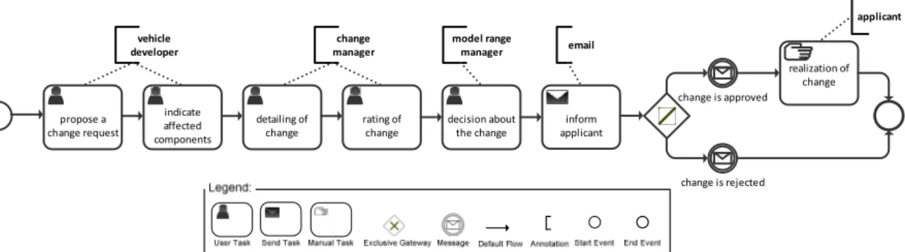
Fig. 2 shows an example of a business process (in BPMN2.01 notation, see OMG, 2009). It describes a simplified process for product changes in the automotive domain. This process ensures that change requests for components are verified and authorized before they are realized. A change request is created by completing a change request form. Since changes usually affect several parts, additional information on these parts must be gathered. Then, the change request will be detailed and evaluated by the responsible change manager. Depending on this evaluation, a decision is made whether or not the proposed change request will be implemented.
propose a change request
indicate affected components
detailing of change
rating of change
decision about the change
inform applicant
change is approved
applicant
realization of change vehicle
developer
change manager
model range
manager email
change is rejected
Fig. 1 Business process model for a change request in the automotiv domain (in BPMN notation)
Based on this business process, a new service-oriented information system can be implemented. This software implementation, however, is executed by software engineers. They do not make business- relevant decisions during system implementation, but take over the information and requirements documented in the business process instead. For a platform-specific implementation of a service-oriented additional information beyond the respective business process become necessary: for instance, data objects, implemented services, user interfaces (such as mask design), business rules, and underlying organizational models. We refer to the corresponding technical description of a business process as executable model process (short: executable process) or service composition schema. The executable process has to be complete and formal to be executable by a workflow engine. Moreover this technical description must meet all demands of the Meta Model used by the engine (e.g. BPEL (OASIS, 2007), BPMN 2.0 (OMG, 2009), ADEPT (Dadam, & Reichert, 2009)). The concrete meta model that has to be used depends on the execution platform chosen. For example IBM WebSphere Process Server (WPS) is using an extension of BPEL in version 6.2, which is strongly oriented at BPMN (IBM, 2008b).
1 A detailed description of all BPMN 2.0 modeling components can be found on http://bpmb.de/poster.
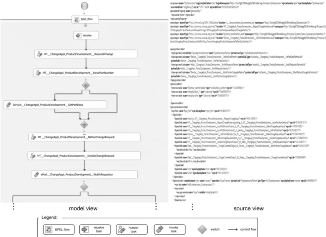
Specialists for designing a service composition schema are usually not present in business departments, but the respective responsibility lies with the IT department. In many companies, the required expertise is not available at all. Consequently, the implementation of the service composition schema is often outsourced to external software vendors. Fig. 2 shows a part of the service composition schema of the business process we depict in Fig. 1.
Fig. 2 Service composition schema (cf. Fig 2) designed in WebSphere Integration Developer (in BPEL notation)
Closing the gap between business process management (cf. business process in Fig. 1) and IT implementation (cf. service composition schema in Fig. 2) is a fundamental challenge to be tackled for a SOA. The use of workflow technology is not sufficient to fulfill the requirements for a flexible SOA.
When regarding current practice, the interaction between business and IT departments during the software development process need to be improved in particular. This aspect is usually referred to as business-IT alignment (Chen, 2008): Information systems should meet business requirements and needs more alternatively than present solutions. In addition to a strong process orientation, it becomes necessary that business requirements and business processes are documented comprehensively. Furthermore, loss of information and corruptions in the development process of the service-oriented information system must be avoided. If changes are made to the business requirements (e.g. as documented in Fig. 1), they should be transferred correctly into the implementation of a service-oriented information system (cf. Fig. 2). This should be as quickly as possible. On the other hand, changes to the SOA environment may occur, e.g.
when services are shut down or services migrate to a new version. A flexible reaction on such scenarios is important in any SOA to keep it viable.
To achieve this, an additional model layer is needed to transforming business requirements and processes
(business processes) into a conceptual representation of the IT implementation (service composition schema).
There are several approaches using such intermediate model layer. Examples include MID M3 (Pera, &
Rintelmann, 2005), IBM SOMA (Arsanjani et al., 2008; Arsanjani, 2004), IDS Scheer AVE (Yvanov, 2006) and Quasar Enterprise (Engels, & Voss, 2008). In the Enhanced Process Management by Service Orientation (ENPROSO) approach we target of use an intermediate model layer, the so-called “System Model” (Buchwald, Bauer, & Reichert 2010). In the following sections we will detail the ENPROSO approach.
The responsibility for creating a system model process (short: system process) is located in the IT department. Changes to the system process should be confirmed by the concerned business department.
The representation of the system process has to be understandable to business users. Its contents are the same as in a business process. However, it has to be defined in a complete and formal manner in order to achieve a platform independent IT specification (service composition schema). That means non-formal business process models have to be replacedand detailed in the system process:
Definition 3 (System Process)
A system process SP = (SN, SE, SNT, SET, SEC) is a process that corresponds to Definition 1 with
• System Nodes SN = {sn1, …, snk} (e.g. a technical service call or a human task) ,
• System Edges SE = {se1, …, sel }
• System Node Types SNT, System Edge Types SET and System Edge Conditions SEC corresponding to Definition 1
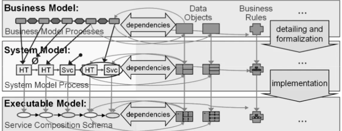
In the ENPROSO project, we pursue a three-level modeling method to realize (and implement) process and service-oriented information systems in a SOA (cf. Fig. 3). All three model layers include relevant process aspects like data objects, business rules, services, and organization model (Reichert, & Dadam, 2000; Weske, 2007). These will be refined in the different model layers (beginning with the business model). Changes to process aspects have to be confirmed by the business department and must be implemented by the IT department (Rinderle-Ma, & Reichert 2009). Therefore, storage of the dependencies between the different model layers is crucial. Different object types relate to each other:
Business processes create different data objects, use business rules, and call services. As the restructuring of the control flow and activities in the business process presents the greatest challenge with respect to model transformations, we focus on this aspect in the following.
Fig. 3: Levels of Process Modeling and other aspects
CONCEPTS FOR PROCESS TRANSFORMATION
This section describes the basic concept for transferring business processes into system processes. The transformation of a business process into a system process requires the adaptation of this process (i.e.
restructuring and detailing of the business process). We introduce the different types of structural changes along our running example from Fig. 1. In addition, we identify various approaches to realize the documentation of the relationship between the different layers of modeling (cf. Fig. 3). Finally, we describe how a system process can be transferred into a service composition schema
Basic Types of Transformations
As discussed above, it is necessary to store all dependencies between business requirements and the corresponding IT realization. For each activity of the business model (and also the corresponding properties and requirements), the corresponding activity of the system model must be derivable (cf. Fig.
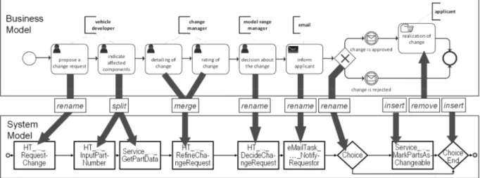
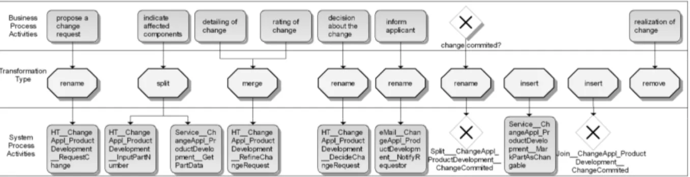
3). Normally, this is not easy to realize, since an IT department usually follows different goals and guidelines than the business department. An example of a simple transformation is the renaming of the business activity [propose a change request] into activity [HT_ ChangeAppl_ProductDevelopment_Re- questChange] of the system process as shown in Fig. 4. Such simple change of labels is easy to handle.
However, we often need a larger restructuring when transferring business process activities into system process activities. This is caused by the differences in modeling information and level of detail between the business departments and the IT departments. Further, manual activities which shall not be automated at all may be modeled in the business process. Their documentation is nonetheless important for process handbooks or activity accounting. Accordingly, manual activities are not copied one-to-one into the system process, but are rather grouped together or even omitted entirely. As our example, consider the activity [realization of change] in Fig. 4. IT-based activities of the business process are often described roughly or not at all. Therefore, they have to be refined or added into the system process. Other business process activities are split in various IT-based activities of the system process (system process activities), for example user interactions, Service Calls, or transformation of data objects. For instance, the activity [indicate affected components] is split into a Human Task (Agrawal et al., 2007a; Agrawal A. et al.
2007b) for user interaction (HT_..._InputPartNumber) and a Service Call (Service_..._GetPartData).
Fig. 4 Transformation between the business model and the system model
Taking account of such transformations, our approach enables transparency of relations between business process activities and their IT implementation. Similarly, transparency is supported in the opposite direction, since it is important for the execution of a service oriented information system that activities
affected by changes in the environment can be identified in the business process. This allows for quick reactions to upcoming changes, like a service shut down.
In the following we describe different types of transformations that occur frequently in practice.
Type 1 (Rename Activities): In the simplest case, a business process activity is mapped to exactly one system process activity. For instance, filling out a form can be realized as a Human Task (Agrawal et al., 2007) in a BPEL process. Activities of the executable model are often subject to naming conventions. This results in different names for activities and data objects in the business model and the system model. To ensure a comprehensible documentation between the different model layers, we have to manage such adaptations explicitly. For example, the business process activity [propose a change request] is realized by the Human Task [HT_
ChangeAppl_ProductDevelopment_RequestChange] in the system process (cf. Fig. 4).
Type 2 (Split Activities): Service-oriented workflow engines require a strict distinction between activities with user interaction (Human Tasks) and Service Calls (BPEL invoke).
This distinction has not been made in service-oriented workflow engines so far. Classical workflow engines, such as IBM WebSphere MQ Workflow (IBM, 2005), or AristaFlow BPM Suite (Dadam & Reichert, 2009; Reichert & Dadam 2009) consider activities as larger units. These units may interact with users and exchange data with backend systems.
Since such units, however, are hardly reusable, they do not meet the basic philosophy of SOA (Erl, 2005;
Erl, 2007; Josuttis, 2007; Mutschler, Reichert, Bumiller, 2008). In the example shown in Fig. 4, it is necessary to split activity [indicate affected components] into a user interaction (to input of the part numbers) and a service call (to determine the remaining part data from a product data management (PDM) system). There are also cases that require more than one service call. For example, data must be read from different backend systems before they can be displayed in a user form.
Type 3 (Merge Activities): During the analysis of business processes, logically related tasks are identified to be modeled by means of separate activities. If activities of a continuous sequence are always realized by the same person, it makes sense to merge them into one system process activity. Nevertheless, this activity can be described as a form flow; i.e. a sequence of forms. In our illustrating example, the business process activities [detailing of change] and [rating of change] are merged to one activity [HT_..._Refine- ChangeRequest] in the system process.
Type 4 (Insert Additional Activities into the system process): After the decision board has permitted the change and the requestor is informed accordingly, the change may be carried out.
In order to actually implement it, the affected components have to be set into state changeable in the PDM-System. This is done by a service call [Service_MarkPartsAsChangeble], which is inserted by a specific transformation type into the system process. Often, additional activities for the logging of relevant events or errors that occurred are necessary as well.
Type 5 (Remove Activities from the Business Process): A business process often contains activities whose execution should not be controlled and monitored by a workflow management system. In our example, activity [realization of a change] will be performed autonomously by an engineer. Consequently this activity shall not be to be implemented in a workflow management system, but is important at the business model level for calculating processing times and simulating process costs. Similar scenarios exist for activities that describe the
“welcoming of a customer” or “conducting a sales conversation”.
If required, additional types of transformations may be defined, for example, the transformation of m activities of the business process into n activities of the system process.
Type 2 A
X Y
Type 1 X A
Type 3 X
A B
Type 4 X
Type 5 A
Generally, it is by far not trivial to identify the relations between business process activities and corresponding technical system process activities. Therefore, all transformations that were performed between business process activities and system process activities have to be stored explicitly. The way we suggest to realize such functionality is described in the following.
Dependencies between business process and system process
A traceable documentation of dependencies is fundamental for closing the gap between business processes and their corresponding IT implementation. In this section, we examine fundamental approaches for transforming a business process into a system process:
Approach 1 (Copying Business Processes): The business process is copied into the system process before it is restructured. System processes are typically created with another tool than the business process. In such case, a tool change must be carried out (e.g. from a business process modeling tool like ARIS into a CASE tool). This tool change makes it difficult to copy business processes directly into processes of the system model. To realize this, a special import functionality is necessary. Different meta models for business processes and processes of the system model (e.g. eEPCs and UML Activity Diagrams) and the limited import functionality of existing typically tools result in loss of information during the import. Often, it is even more appropriate to model the system process manually from scratch.
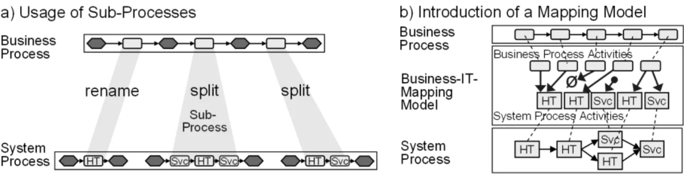
Approach 2 (Using Sub-Processes): One possibility for refining process information also supported by existing tools is to introduce sub-processes. As shown in Fig. 5a, for example, an activity of the business process can be detailed by a whole sub-process. The relationship between the activity of the business process and the sub-process in the system model remains visible. For example, this can be realized in ARIS by referencing a sub-process through a so-called “assignment” of the original activity. If a tool change takes place in respect to the modeling of the business process and the system model, it is necessary to import the business process into the system model (cf. Approach 1).
In this variant only the renaming (cf. Basis Types of Transformation, Type 1), splitting (Type 2) and removal (Type 5) of activities can be realized. Merging of activities (Type 3) is not possible since Approach 2 is only applicable to single activities. Likewise, insertion of activities (Type 4) is not possible, since no object exists in the business process that can be refined in the system process.
Moreover, the (overall) structure of the business process no longer exists on the system process level. The structure of the system process can only be reconstructed via the business process itself and the corresponding refinement relations. This is very confusing for the process designer and renders the derivation of a service composition scheme cumbersome.
Fig. 5: Variants for managing relationships between business process and system process.
Approach 3 (Business-IT-Mapping Model): We now introduce a new type of model whose instances are called Business-IT-Mapping Model (BIMM). BIMMs describe in which way activities from the business process are transferred into activities of the system process. Likewise, all system process activities can be traced backwards to the business process activities they originated from. With this new
model we can define all required types of transformation.
Business processes are often modeled using business modeling tools whereas system processes are realized with CASE tools. The purpose of the BIMM is to document relationships between business processes and system processes. It describes no order (control flow) between the activities of the system process model. Thus, only individual activities have to be exported from the business modeling tool and have to be imported into the system process modeling tool (cf. Fig. 5b). This is easy to realize, because there is no meta model change necessary for a process graph.
Approach 3 allows for the documentation of all types of transformation. It is expandable by adding additional types of transformation. All changes made in the business process or in the system model are immediately obvious. The dependencies between activities from the business process and system process activities are bidirectionally traceable. A disadvantage of this approach is the need to define the additional BIMM as well as the effort to define and manage this model by hand. Since all other approaches have serious disadvantages, we opt for Approach 3.
Transformation of the system process into a service composition schema
As mentioned above, the transformation of the system process into a service composition schema should be as simple as possible, since the executable model is often implemented by external service providers or IT departments, who do not have any knowledge about the corresponding business process.
The transformation between these models should be one-to-one. All aspects modeled in the system process are transferred to the service composition schema. These aspects are formalized and detailed depending on the necessities of the target platform: For example, a system process is documented as a UML Activity Diagram and should be implemented as a BPEL Process. In addition, manual activities are documented as Human Tasks in the system process (Agrawal et al., 2007). Moreover, it is necessary to use suitable BPEL constructs (e.g. While, Parallel-ForEach) to realize the control flow defined in the system process as a BPEL process.
The traceability between these models is straightforward, since every aspect of system process is directly transferred into the service composition schema. Identification of corresponding objects (e.g. activities) between the models is possible via their names. Only for the special case that the system process does not fulfill the naming conventions of the target platform, an additional table to map names is necessary. This table has a simple structure since a system process activity is always assigned to exactly one activity of the service composition schema.
There are no relevant challenges regarding the traceability between the system model and the executable model. Hence, this transformation will not be considered further in the following sections of this chapter.
DESIGN OF THE BUSINESS-IT-MAPPING MODEL
The business process modeling tools (e.g. ARIS or MID Innovator) and notations (e.g. eEPC (Scheer, Thomas, & Adam, 2005), BPMN (OMG, 2009) or UML-Activity Diagrams (OMG, 2004)) are usually selected by the respective business departments. Likewise, the implementation platform or language (e.g.
IBM WebSphere Process Server and BPEL (OASIS, 2007)) normally can not be chosen freely by the software developers. On the other hand, the system model must meet certain requirements, like comprehensibility. In principle, an IT department can choose between several modeling languages (e.g.
eEPC, BPMN), if there is no company policy for a specific notation or a modeling tool. Notations and tools have some impact on the quality of the BIMM, which will be discussed later.
The BIMM, as shown in Fig. 5b, defines a connecting link between business processes and system processes. Currently, this link is not supported by business process modeling or CASE tools. In the following sections we will explain how a BIMM should be designed. This is important to ensure the traceability between a business process and system process. Finally, we show how the example scenario (cf. Fig. 1) can be realized by selected notations.
Structure and Internal Consistency
The BIMM is defined during the development of the system process. The IT department has the responsibility for the BIMM as well as the system model. Therefore, the same modeling tools and the same notations should be used for designing of the BIMM and the system process.
In general, the BIMM defines a set of relations which map the activities of the business process to activities of the system process. Each of these relations corresponds to exactly one transformation type. A relation should be always realized by some unique object in the BIMM (and not only by edges). This object describes the type of the transformation and additional attributes like the name of the transformation, its description, or the contact from the business department who approved the transformation. We define a BIMM as follows:
Definition 4 (Business-IT-Mapping Model)
Let BIMM = {Transf1, …, Transfk} be a Business-IT-Mapping Model for a business process BP = (BN, BE, BNT, BET, BEC) and a system process SP = (SN, SE, SNT, SET, SEC) with
• the transformation Transfi= (N1, N2, OpType) with N1 is a set of nodes,
N2 is a set of nodes and
OpType ∈ {Map, Split, Merge, Remove, Insert}
• The following functions are defined:
BNodes(Transfi) provides the nodes N1 SNodes(Transfi) provides the nodes N2
OpType(Transfi) provides the corresponding Transformation Type OpType
To ensure internal consistency, it is necessary to define the types of transformation correctly:
Definition 5 (Internal Consistency of the Business-IT-Mapping Model)
BIMM = {Transf1, …, Transfn} is a consistent Business-IT-Mapping Model if ∀ Transfi ∈ BIMM the following conditions are fulfilled:
• ¬∃ (Transfi and Transfj) with:
∃ n with n ∈ BNodes(Transfi) and
∃ s with s ∈ SNodes(Transfi)
• if OpType(Transfi) = Map then:
| BNodes(Transfi)| = 1, i.e. exactly one source node in N1 and
| SNodes(Transfi)| = 1, i.e. exactly one target node in N2
• if OpType(Transfi) = Split then:
| BNodes(Transfi)| = 1, i.e. exactly one source node in N1 and
| SNodes(Transfi)| > 1, i.e. actually more than one target node in N2
• if OpType(Transfi) = Merge then:
| BNodes(Transfi)| > 1, i.e. actually more than one source node in N1 and
| SNodes(Transfi)| = 1, i.e. exactly one target node in N2
• if OpType(Transfi) = Remove then:
| BNodes(Transfi)| = 1, i.e. exactly one source node in N1 and
| SNodes(Transfi)| = 0, i.e. no target node in N2
• if OpType(Transfi) = Insert then
| BNodes(Transfi)| = 0, i.e. no source node in N1 and
| SNodes(Transfi)| = 1, i.e. exactly one target node in N2
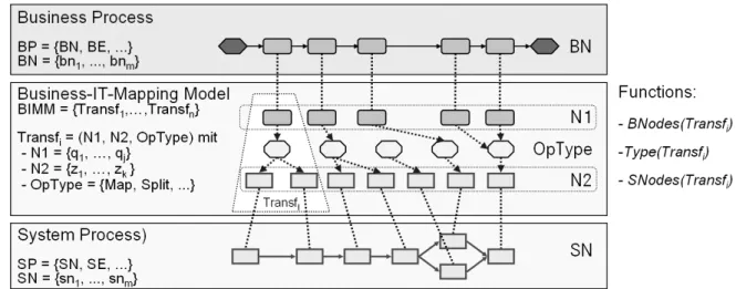
Fig. 6 shows our ENPROSO modeling approach including the previously established BIMM to document relationships between the business process and the system processes.
Fig. 6 Business-IT-Mapping Model to document relationships
Current modeling tools do not support the concept of our BIMM. Therefore, we have to use and adapt an existing model type in order to realize the BIMM (e.g. as an eEPC, BPMN model or UML Activity Diagram). This model type must store business process activities, system process activities, and also dependencies between them. Depending on the notation and the tool, a special model type can be derived for BIMM. To realize the transformation between business process activities and system process activities, special types for nodes as well as edges are used.
Fig. 7 shows a BIMM which correspond to the example introduced above (cf. Fig. 4). This BIMM is designed in a “neutral” notation. Transformation types are visualized by octagons to differentiate them from business process activities and system process activities. Transformation edges between activities and transformation types are shown with dashed directed edges.
Fig. 7 : Business-IT-Mapping Model for the example scenario presented in Fig. 1
Overcoming the Limitations of Existing Tools
A BIMM includes business process activities, system process activities and also relations between them.
The meta model that is appropriate to realize a BIMM depends on the notations and the tools used for these two models. To document the dependencies between business process activities and system process activities in the BIMM, it is necessary to realize references to activities in both models. This can be achieved easily if both models are specified in the same tool. Frequently, however, the BIMM is created with different tool than the business process. The gap between tools must thus be managed in referencing.
For this purpose, there are basically the following options:
Option 1 (Exporting Activities): The activities of the business process are exported by using a standardized interface (e.g. as XML file) and imported into the system process. Copies of activities from the business process are now available in the system process. They contain an identifier (ID) referencing the activity in the business process. Thus, an unambiguous identification of corresponding activities in the business process is possible. In addition, descriptive data on activities from the business process should be imported into the system process, e.g. the name of the responsible person in the business department.
If there is no export and import functionality no appropriate exchange format between different tools, it is sufficient to read the ActivityID in the business process and store it in the system process activity manually.
Option 2 (Using a Repository): Another option is the usage of a repository (Buchwald, Bauer, & Pryss, 2009). In this case, there is no need for bilateral interfaces between different tools, since Business Activities are stored directly in the repository. During the design of a system process stored business process activities can be imported. Subsequently, the IDs of the business process activities are explicitly managed by the repository (Buchwald, Tiedeken, Bauer, & Reichert, 2010).
The SOA repository can even play an additional role if it stores the whole Business-IT-Mapping Model.
To achieve this, every object and relation between business processes and system processes must be stored and managed by the repository. It can thus be traced which system process activity relates to which business process activity. Furthermore, long-term storage of the BIMM and the corresponding dependencies (even if the modeling tools become unavailable) can be realized. Because of the tool- independent interface of a SOA repository, it can be used by different partners and various tools. This is important if there are tool changes in a later phase of the development process.
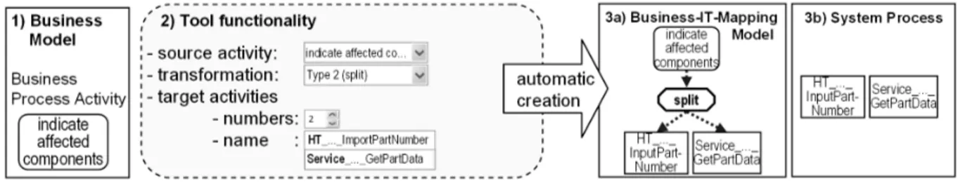
Tool support for Generating the Business-IT-Mapping Model
The BIMM can be created and managed manually. However, a support tool would be helpful. Special tool functionality is required to generate the BIMM (semi-) automatically. Fig. 8 shows how to generate such a model: For instance, the business process activity indicate affected components (cf. Fig. 4) is chosen for detailing (1 in Fig. 8). The tool should offer functionality to select the business process activity (2: source activity) and the desired transformation type (2: Type 2 split). Additionally, the number and the corresponding names for the system process activities (2: target activities) have to be defined. With this information, the corresponding BIMM fragment (3a) can be created automatically. Furthermore, the new system process activities are created in the system process (3b). They constitute the basis for the process definition (by drawing edges, etc.).
Fig. 8 Tool functionality, the example of the Transformation Type 2 (split)
USAGE OF THE BUSINESS-IT-MAPPING MODEL
The BIMM enable traceability of performed transformations between business processes and system processes. Furthermore a fast mapping (and implementation) of altered business requirements to activities of the executable model (service composition schema) are provided. Likewise when changes in the environment of the executable model like the shut down of a service (cf. Fig. 4, Service_GetPartData) occurs, the corresponding business activities can be identified easily (cf. Fig. 4, indicate affected components). Thus, responsible business managers can be informed quickly in order to authorize such changes. Finally, BIMM information can be used at runtime to monitor activities (Business Activity Monitoring, BAM (Amnajmongkol et al., 2008)). This is useful, for example, to check whether the defined business requirements are met (e.g. processing time of a task).
In this section, we describe how to deal with changes to the business process or the service composition specification. As discussed above, it is important to ensure the consistency between the different model layers (cf. Fig. 3).
Ensuring Consistency between Model Layers
One advantage of the BIMM is that it allows to ensure consistency between the different model layers.
Thus, errors in implementation can be avoided. In addition, changes at the business model level or at the executable model level can be identified via a consistency analysis. Below, we describe requirements concerning the consistency between the different model layers:
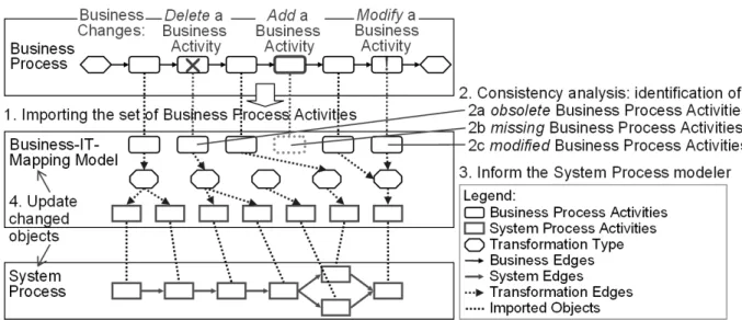
Consistency Requirement 1: Changes are usually initiated by the business department. These business changes must be propagated into the other models (cf. Fig. 9). Our BIMM approach offers the basis for automated analysis of consistency. For this purpose, after changing a business process all business process activities have to be imported into the BIMM (cf. Step 1 in Fig. 9). The consistency analysis then compares the set of imported activities in the BIMM with the existing ones (Step 2). If source activities in the BIMM do no longer exist, they have been deleted from the business process (Step 2a). This information is communicated, for instance, in the form of a report to the business process modeler (Step 3). Therefore, a software developer adapts the BIMM and the system process appropriately by removing these activities. For this case we have defined an inconsistency rule (R1 in Definition 6-1). This rule identifies the deletion of business process activities.
If business process activities are added to the business process, the consistency analysis will recognize identifies that source activities are missing in the BIMM (Step 2b). Then, if the activity has technical relevance the modeler has to update the BIMM and the system model suitably. For this case, we have defined another inconsistency rule (R2 in Definition 6-1).
Definition 6-1 (Structural Inconsistency)
Let BP = (BN, BE, BNT, BET, BEC) be a business process, SP = (SN, SE, SNT, SET, SEC) a system process and BIMM = {Transf1, …, Transfn} a Business-IT-Mapping Model. Then, there exists an inconsistency if one of the following rules is fulfilled:
• Inconsistency Rule R1: ∃ Transfi∈ BIMM, ∃ bn ∈ BNodes(Transfi) with: bn ∉ BN
• Inconsistency Rule R2: ∃ bn ∈ BN and ¬∃ Transfi∈ BIMM with bn ∈ BNodes(Transfi)
Consistency Requirement 2: If accessible timestamps for business process activity objects are supported by the business process modeling tool (e.g. the attribute “last modified” that is maintained by ARIS), changes on individual business process activities can be identified. The consistency analysis not only compares the updated with the existing set of business process activities, but also the time stamps of individual business process activity objects. For this purpose, the timestamp of the business process activity is exported. This timestamp is then saved in the corresponding object of the BIMM. After re- importing the business process activities into the BIMM, activities with modified timestamps can easily be detected (cf. Step 2c in Fig. 9). If Inconsistency Rule R3 is applies, a business process activity of the business process has been changed (R3 in Definition 6-2).
Of course, there are changes which can be ignored by modelers of the system process because they are irrelevant to the IT implementation (e.g. changes in costs for execution of activities that are relevant only for a process simulation and analysis). An analysis of changes provides a superset of the actually necessary adaptations. Nevertheless, it is crucial to ensure that no changes remain undetected.
Definition 6-2 (Structural Inconsistency – Continuation Part 1)
• Inconsistency Rule R3: ∃ bn ∈ BN with related bn′∈ BNodes(Transfi) and Timestamp(bn) >
Timestamp(bn′ )
Fig. 9: Consistency analysis for business changes
Consistency Requirement 3: Not all changes are initiated by the business department (cf. Business Changes in Fig. 9) in practice. Often, it is necessary to implement changes directly in the system process (or even in the service composition schema of the executable model) without adaption of the business process. For instance, this may be the once when quick reactions to changes in IT operations, like the sudden suspension of a service, become necessary. We call such changes environment changes. They can be identified by consistency analysis based on the BIMM as well: If an activity is removed from the system process, the consistency analysis detects that the corresponding activity still exists in the BIMM (R4 in Definition 6-3). Together with the business department, a decision is made whether only the BIMM should be modified (so that the inconsistency is resolved), or if the proposed change also affects the business process.
Additionally, our consistency analysis detects the absence of newly added system process activities in the
BIMM (R5 in Definition 6-3). A frequently occurring case is that already existing system process activities are changed, e.g. a new service version is called or a staff assignment rule was modified (Erl et al., 2009). Such changes can be identified by comparing the timestamps (analogous to consistency requirement 2): If Inconsistency Rule R6 (Definition 6-3) is fulfilled, an activity of the system process has been changed. Subsequently, the timestamp of the corresponding activity in the BIMM is updated. The change should also be propagated to the business process, if it is relevant from the business perspective.
Definition 6-3 (Structual Inconsistency –Continuation Part 2)
• Inconsistency Rule R4: ∃ Transfi∈ BIMM, ∃ sn ∈ SNodes(Transfi) with: sn ∉ SN
• Inconsistency Rule R5: ∃ sn ∈ SN and ¬∃ Transfi∈ MM with sn ∈ SNodes(Transfi)
• Inconsistency Rule R6: ∃ sn ∈ SN with related sn′∈ SNodes(Transfi) and Timestamp(sn) >
Timestamp(sn′ )
If R1…R6 is not fulfilled, BIMM is consistent to BP and SP.
To quickly identify changes, modelers have to be informed actively. Therefore, a visualization of information about changes directly in the system process is useful (cf. Step 3 in Fig. 9): A task list integrated in the corresponding modeling tool can help to visualize all changes to be implemented.
Subsequently, the modeler marks changes in the task list which he has already considered (cf. Step 4).
Alternatively or additionally affected system process activities can be highlighted until the modeler has confirmed the elimination of the inconsistency. Both variants prevent changes from avoiding notice. For the realization of these variants, it is a prerequisite that the modeling tool offers a (expandable) functionality for task list management and for marking activities.
Application Scenarios and Enhancements
A further usage of the BIMM is possible if its information set is expanded. In the following we describe two potential enhancements for the BIMM:
Enhancement 1: The control flow (sequence, loops, etc.) between business process activities could be included into the BIMM in order to detect changes automatically after a re-import (for instance, switched order of activities). As mentioned above, the transfer of business processes into another modeling language is difficult. Changes in the control flow can easily be detected by comparing the two model versions of the business process (which is supported by conventional modeling tools directly). Therefore, we do not suggest storing the control flow in the BIMM. The resulting efforts should be avoided.
Enhancement 2: Similarly, we can use information about the control flow of the system process stored in the BIMM: If we know in which order system process activities are executed (for example, after a split transformation in the BIMM), it is possible to generate parts of the system process automatically.
Together with the information about the control flow of the changed business process, the whole system process can be generated anew. This means that the previous version of the system process will be discarded. However, an automatic generation of the entire system process is hardly realizable in practice.
Due to the vague and informal description of the business processes, it is extremely difficult to formally specify the resulting (complex) transformation rules. For instance, cases exist in which business process activities are modeled sequentially in the business process and should be ordered in parallel in the system process (e.g. to reduce the execution time). Likewise, a split of a business process activity does not always result in system process activities that follow each other directly. This can not be described by a flow-control fragment in the BIMM.
Therefore, we pursue a fundamentally different way then the one described in Enhancements 1 and 2: The last existing (and extensively documented) version of the system process is remains in place (i.e. it is not discarded). Required changes (for example initiated by new business requirements) are propagated subsequently into this system process. In our opinion, this approach results not only in a better quality of system processes (now created manually), but also in less maintenance effort of the various models: The
BIMM has to store only the dependencies between business process activities and system process activities. Therefore, it is not necessary to maintain complex control flow fragments or to define rules how to apply them.
PROOF-OF-CONCEPT IMPLEMENTATION
In the following section, we describe how to realize a BIMM by using the Business Process Modeling Notation (short: BPMN). To this end, we use the application example from the Background section. We discuss the difficulties that occur during modeling. In addition, we demonstrate how our approach can be implemented with today's process modeling and process execution tools. We first use the IBM WebSphere Business Modeler 6.2 (WBM) (IBM, 2008a) tool. This tool focuses more on the specification and execution of service compositions (compared with tools for the pure business process modeling like ARIS). In addition, it enforces the compliance with certain guidelines. For comparison, we present also an implementation in ARIS which uses BPMN notation for realizing the BIMM.
IBM WebSphere Business Modeler
A BIMM2 can be created by IBM WebSphere Business Modeler (cf. Fig. 10). The BPMN swimlane representation separates the objects (activities) from the business process and the system process, and also the transformation nodes between them. An object type categorization enables additionally marking by colors. In addition, the names of the transformation nodes are chosen in a way that the type of transformation is easily recognizable. The uniqueness of these nodes is achieved by sequential numbering. For a more detailed description, special names can be chosen for the basic transformations (e.g. “Insert: Service for changing the state in the Product Data Management System”).
Fig. 10 BIMM designed with IBM WebSphere Business Modeler
The creation of the BIMM with the WBM tool is more difficult because some functionality is missing.
For instance, there is no comfortable possibility for copying business process activities into the BIMM and subsequently making a reference to the same Object Instance in the business process (cf. ARIS Assignments).
2 The corresponding Business Process Diagram (cf. Fig. 13) and the system process Diagram (cf. Fig. 14) can be found in the appendix.
Further difficulties arise because of the technical focus of WBM: Since the process models have semantics for execution, it is necessary to define input and output data (known as ports) for all activities, as well as the data flow. Thus, we also have to define a data flow for the edges of the transformation nodes although it does not really exist. If we do not define all input and output data of objects in our BIMM, we get some error messages. The associated data flow objects can be chosen arbitrary. In these objects can be hidden by a special view (modeling mode) in WBM. If we use the modeling mode “basic”, error messages and warnings for undefined data objects are hidden. One should be aware, however, that these errors exist, even if they are not relevant because no deployment of the BIMM is planned.
Aris Business Architect
As shown in Fig. 11 it is also possible to design a BIMM by using the ARIS Business Architect 7.1.
Again the model is realized in BPMN notation. The BIMM includes business process activities of a corresponding business process (cf. Fig. 15) defined as an extended Event Driven Process Chain (short:
eEPC) and system process activities of a corresponding system process (cf. Fig. 16). The different model layers are structured by using BPMN swimlanes.
Fig. 11 Business-IT-Mapping Model desiged by using ARIS Business Architect 7.1 (BPMN-Notation)
The clarity of the presentation results from using derivations of existing object types. These so-called Sub-Types can have their own styles of visualization (their own symbols). This functionality is also used to define special symbols to visualize transformation nodes in the BIMM (like in Fig. 7). In addition, a special configuration of the ARIS Business Architect allows us to visualize specific attributes for each object. This allows for displaying an unambiguous name for structural nodes (e.g. for branching). It is not possible to define a special transformation edge between business process activities and transformation nodes (or between transformation nodes and system process activities) in the BIMM (cf. Fig. 11). To this end, we use the edge type “is predecessor of”.
Referencing business process and system process activities in the BIMM is easy to realize in ARIS: The ARIS object approach demands that each object (e.g. an activity) modeled in a diagram has exactly one corresponding object stored in the ARIS database. This allows for the copying of activities from business processes and system processes and the subsequent storing of these activities in the BIMM as so-called
“assignment copies”. Changes applied to objects (e.g. activities in the business process or in the system process) affect all assignment copies, because they reference the same ARIS database object. This keeps the names of activities and other attributes up to date in the BIMM if changes occur in business processes or in system processes.
Another advantage of using ARIS is that edges between objects do not describe the data flow explicitly.
Thus, the problem of WBM transformation edges will not occur because transformation edges need not be connected to specific output parameters of a business process activity in the BIMM. Similarly, it is not defined whether activities (from the BIMM) have additional output parameters or attributes, because these are exclusively specified in the corresponding business process or system process. The modeling of a
BIMM with ARIS is easier than using WBM, since ARIS is less formal and has no execution semantics.
The reason for this is that the tool is not intended to be used to specify the IT-view of an information system, but to design business processes.
However, this is also a disadvantage for the usage of ARIS, because the ARIS Business Architect is not a tool for users of IT departments and not commonly used for the creation of system processes. It is not expected that an IT architect will implement his (UML-) classes or data objects in ARIS in order to develop the IT specification.
Conclusion
We have examined two different modeling tools. Both tools have shown that a BIMM can be realized as a BPMN diagram in principle. The result was clear and buildable with little effort: The creation of a single transformation node with the corresponding edges and the usage of existing business process activities and system process activities is possible in a few seconds up to minutes. Therefore, both tools are suitable for the creation of a BIMM.
Although BPMN diagrams can be used for designing BIMMs, they actually describe only a temporary solution. BPMN diagrams should be used only until process modeling tools implement their own type of BIMM.
RELATED WORK AND DISCUSSION
In the literature, we can find a number of approaches addressing issues related to modeled business processes and their transformation into executable models. First, we consider approaches which realize transformations between different meta-models. Subsequently, we discuss approaches such as MDA (Model-Driven Architecture) and MDSD (Model-Driven Software Development), and also the modeling methods of various manufacturers.
Model layer transformation: Existing literature discusses two fundamentally different types of (meta-) model transformations: first, the direct transformation of business processes (e.g. eEPC or BPMN) into executable models (e.g. BPEL or BPMN), and second, the transformation including an additional model layer (e.g. eEPC or BPMN).
In the first case, the business process is usually limited by restrictions (e.g. non-cyclic models). Ziemann,
& Mendling (2007) use the XML-based exchange format EPML (Mendling, & Nüttgens (2006)) for eEPC models to transform these into BPEL. Because of limitations in the eEPC model a direct transformation into a BPEL model can be realized. This approach has to be re-applied if changes are made at the business process layer, e.g. inserting a new business process activity. Thus, changes that have already been implemented in the BPEL model will be lost. Nevertheless, this approach provides a basic mechanism for transforming acyclic eEPC models into BPEL models.
There are other similar approaches: van der Aalst, & Lassen (2005) describe how a workflow net can be transformed into a BPEL model and Gardner (2003) discusses automatic mapping of UML models into BPEL models. Basic transformations of BPMN to BPEL are described in the BPMN standard (OMG, 2009), White (2005), and Ouyang et al. (2006). The latter approach details the transformation of a non- restricted BPMN model into a BPEL model. Additionally, this approach describes an algorithm that transforms BPMN models into BPEL models automatically. First, the algorithm scans the BPMN model for certain patterns. Subsequently, it replaces them by custom-defined components that allow a direct mapping into BPEL.
In the second class of approaches, an intermediate model between the business process layer (e.g eEPC) and the executable model layer (e.g. BPEL) is introduced: Thomas, Leyking, & Dreifus (2008) describe the transformation of an eEPC model into a BPEL model and uses an additional BPMN model as intermediate layer. The idea is, analogous to our approach, to improve Business-IT alignment. However, it is not a goal to make the relationship between activities of the different layers transparent. The starting
point for the transformation is the flow logic of the business process (eEPC). Previously defined mapping constructs transform the business process activities into an intermediate model (BPMN). This BPMN model is subsequently enriched by technical details (particularly for the process execution) and is transformed into a BPEL model.
Other approaches, such as Weidlich, Weske, & Mendling (2009) compare various models for similarities.
If changes are made on a model, they can be assigned to similar models. Approaches concerning requirements engineering deal with the bidirectional propagation of changes on requirements and related UML models (Rupp, 2007).
Model driven approaches: Several related works are based on standardized approaches such as MDA and MDSD.
Allweyer (2007) describes an approach that is independent form the modeling notation, which transforms (coarse granular) business processes into executable processes. To realize such a transformation, different patterns will be defined in the business model (eEPC). These patterns specify the technical detailing of objects (e.g. business objects from the business process) and describe how these objects may be transferred into the executable model (BPMN). Subsequently, transformation rules implement such transformations.
Bauler et al. (2008) describes how to define business patterns and technical patterns and how to apply them on various business processes. Thereto, business patterns are applied on coarse granular BPMN models. The resulting model is called “extended BPMN model”. Based on this model an automatically transformation generates an executable model (so-called pseudo-BPEL). It is transferred in a further step into an executable model (BPEL) by using additional technical patterns.
The OrVia project (Stein et al, 2008) uses a similar approach: it describes a method for an automatic and tool-assisted transformation of eEPC models into executable BPEL models. Predefined patterns are used here as well. eEPC models will be transformed into BPEL models by the usage of such patterns.
Model driven approaches generate their executable models by using patterns. However, such approaches for the generation of executable models are not always realizable. This also applies to our scenario where free modeling of the system process is required: Therefore, for business processes (mostly described coarsely granular and vaguely), a structural adaptation at the system process layer is necessary. To realize such an adaption using automatically applicable patterns would be too complex and costly, because extensive transformations between objects from the business process (e.g. activities) and objects from the system process have to be defined. Additionally, transformations like inserting new activities in the system process are hard to realize, since there exist no corresponding activity in the business process to which a pattern can be applied. In our scenarios, business processes are different, so that a reuse of predefined patterns in various business processes is not realistic. In addition, the “technical problem” with pattern definition that was mentioned at Enhancement 2 occurs with these approaches. Therefore, for each business process, it must be decided individually how a corresponding technical representation can be realized in the system process.
In addition to these model-driven approaches, there are service-oriented approaches which support a model-driven development of information systems (De Castro, Marcos, & Wieringa, 2009). Furthermore, there are approaches describing how to transform models into another notation. Ouyang et al (2009) present a technique that allows transforming BPMN models into readable (block-structured) BPEL models. Such a transformation is defined unidirectional. As a result, inconsistencies occur if changes are made in the BPEL model.
Methods of software manufacturers: Software manufacturers usually recommend a different approach.
Similar to our proposal, they introduce an additional model layer between the business model layer and the executable model layer.
The modeling methodology M3 of the company MID is based on a MDA approach. This methodology is subdivided into three variants (Pera, & Rintelmann, 2005). When compared to our approach some similarities are interesting to note for the variant “M3 for SOA”. This method provides extensions for
Innovator (MID, 2008) for each model type in the form of UML “stereotype”. The modeling takes place at three levels. The first level describes the business model, in which business processes are defined freely and without modeling restrictions. Subsequently, use cases are derived from the business process description. The latter describe the requirements for the information system to be developed. Based on these use cases and additional information from the business processes, a platform-independent “analysis model” is generated. This second layer is comparable to our system model layer. It describes, for example, classes and data models, and also process descriptions that are required to implement the business processes. At the third model level a platform-specific model is described which specifies the target platform and language. This platform-specific model is supplemented by technical information.
Other manufacturers like IBM (Arsanjani et al, 2008; Arsanjani, 2004), IDS Scheer (Klückmann, 2007), Enterprise SOA (Woods, Mattern, 2006), Model-Driven Integration of Process driven SOA Models (Zdun, Dustdar, 2007; Tran, Zudan, Dustdar, 2008) or Quasar Enterprise (Engels, & Voss, 2008) describe similar methods in order to transfer business processes into an IT implementation. They also use different model layers to realize the mapping between business processes and their IT implementation. However, none of these methods document the dependencies between business process activities of various levels in a traceable and understandable way.
Conclusion: In our project ENPROSO, we use these approaches as a basis in order to realize fundamental transformations between different modeling languages. At some approaches, the necessity of an intermediate model (system model) is identified and partially implemented. A BIMM that ensures traceability between a business process and a system process has not been discussed in any previously existing approach.
CONCLUSION
Business processes (created by business departments) must be adapted structurally before they can be implemented within a workflow management system. This chapter describes an approach which allows for a quick and transparent transfer of business requirements into information systems (cf. Fig. 11). To achieve this, we introduced a new model layer (system model) between the business model and executable model. This model is in the responsibility of the IT department and serves as specification for the IT implementation. An additional Business-IT- Mapping Model (that is part of the system model) enables the transparent documentation of the transformations that were applied to the business processes in order to define the system process and the executable process (service composition schema). This traceability is used to create or adapt an IT implementation more quickly. It also ensures the consistency between the model layers. The approach for the realization of a Business- IT-Mapping Model is described in detail and realized prototypically.
We have shown how flexibility can be increased in the development of service- and process-oriented information systems. Our approach ENPROSO enables the realization of business requirements by an IT implementation with a higher quality and more quickly by:
• ensuring bidirectional traceability between business activities and system activities
• enabling localization of changes in the corresponding model
• enabling automatic identification of inconsistencies between different models
• supporting the modeler when resolving inconsistencies and propagating changes
Fig. 12 ENPROSO three-level modeling method