Model-Based Testing
Fabrice Bouquet, St´ephane Debricon, Bruno Legeard, and Jean-Daniel Nicolet Laboratoire d’Informatique de Franche-Comt´e (LIFC),
{bouquet,debricon}@lifc.univ-fcomte.fr Leirios Technologie,
legeard@leirios.com
Centre des Technologies de l’Information de l’´etat de Gen`eve (CTI), jean-daniel.nicolet@etat.ge.ch
Abstract. The Unified Process (UP) is a software development tech- nique that includes modeling of specifications and testing workflow. This workflow is achieved by information interpretation of specification to pro- duce manual tests. In this paper, we extend the UP with model-based testing (MBT) where models resulting of the UP will be used for MBT.
We describe how model-based testing introduces new test design activi- ties in parallel with the application design activities. We give guidelines to derive the test model from the analysis model produced by the UP.
We illustrate this tailored process with the example of a Geneva State taxation.
Key words: Unified Process, Model-Based Testing, Class Diagrams, Statecharts, OCL, Model specialization
1 Introduction
Model-based testing (MBT) exists as a process [UL06], describing each step needed from creating a test model, automatically generating test cases and exe- cutable test scripts from that model. MBT can then be viewed as an independent process in the development life cycle. To make it more efficient and widely used, our purpose is to include MBT in an existing and recognize process, that is to extend the Unified Process (UP) to support model-based testing key features.
The UP is a software engineering process. Its goal is to transform requirements into software. To realize this transformation we model requirements, using for example the Unified Modeling Language (UML). And then models evolve to be more and more precise and finally an implementation of the system is made.
We propose guidelines to specialize model produced by the UP into model suit- able for test generation. The new process called UPMBT will then support the usual manual writing of test cases, but also the automatic generation of tests from a new artefact called test model. This is a key concept of UP, the ability to be tailored. The most famous version of the UP is the RUP (Rational Unified Process), which comes with tools and support. There are also other example of
tailored UP such as the EUP (Enterprise Unified Process)[Amb05].
In this paper we define an extension of the UP to include the model-based test- ing process. In the first section we will introduce the unified process, and the model-based testing process. In the second section we will describe how the UP evolves to support MBT. We also explain benefits and gains expected in the development process. Then we will propose a way to produce a test model from a model provided by the UP. The last section will present a case study based on the life cycle of a taxation in Switzerland.
2 Overview of the Unified Process and Model-Based Testing
In this section we introduce in more details UP and MBT.
2.1 The Unified Process (UP)
We want to consider a software development technique called the Unified Pro- cess.
The goal of the UP is to define who does what, when and how. The UP is strongly tied to UML [Obj05], but they are actually independent. The UP is the methodology explaining how to transform requirements into software. UML is the visual language necessary to the methodology. Note that UML has been standardized by the OMG. A meta-model exists for both, each of which being an instance of the meta-meta-model named Meta-Object Facility (MOF), de- fined as the nearly universal root from which several other meta-model derive, like for example XMI (the XML format used to store UML models) and CWM (Common Warehouse Metamodel). The meta-model used for the UP is called Software Process Engineering Metamodel (SPEM).
First research leading to the creation of the UP have been done by Ericsson (the Ericsson approach 1967) and Rational (the Rational Objectory Process, 1996 to 1997) now a part of IBM. In addition it is also based on other best prac- tice and guidelines such as managing requirements, visual modeling of software, component-based architectures, iterative development, verifying software quality and managing changes of software.
The UP is organized into four phases, often with several iterations happening inside some of these phases [AN03]. The phases are:
Inception: The goal of the inception phase is to have an overview of the over- all project; this phase should establish feasibility, from technical prototyping to functional behavior modeling. Stakeholders and project management should end up with an agreement on the scope of the project. Major risks have been identified and a business case expressing how the project delivers benefits to the business is available. The inception phase should evaluate the cost and produce a schedule for the project.
Elaboration:The goal of the elaboration phase is to produce a working skele- ton of the architecture of the project. This skeleton will capture some of the most risky functional behavior expressed in the requirements. By the end of this stage, most of the use cases have been written, the hard engineering decisions have been made and the final commitment of whether or not continue with the project can be made.
Construction:The goal of this phase is to build the product. The construction phase is usually a series of development iterations that flesh out the function- ality of the skeleton into a deliverable product. Each iteration goes for one to two months, has a fixed deadline and produce a release that can be tested and evaluated by users.
Transition: The goal of this phase is to deliver the finished product to the users. This includes deployment, beta-testing, completion of the user documen- tation, training of the end users and reacting to user feedback. A project review is done to evaluate the process.
2.2 Model-Based Testing (MBT)
The objective of testing is to find defects in software. To achieve this goal, one must be able to find differences between an implementation and what stakehold- ers expressed in requirements.
One way to do this is to use model-based testing; it relies on a behavior model, precise enough, of the requirements. The testing model should capture the ex- pected behavior with sufficient abstraction; we don’t want to consider every detail.
An implementation should offer an adequate solution to every requirement ex- pressed whether they were formal or not. In fact, if we consider a model as detailed as the System Under Test (SUT), we would rather validate the imple- mentation.
Abstraction is a necessity for model-based testing, but any omission will lead to the impossibility to generate tests for the omitted part. It is a question of choice, for the modeler, whether he wants tests for a requirement or not.
Models should be abstract but precise and complete enough to generate the required test case and the expected results (the test oracle). The models we consider are universal rather than existential abstractions - e.g. state machine diagrams or pre-post conditions as opposed to sequence diagrams [UPL06].
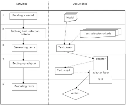
We will consider a template for a process conducting the generation and ex- ecution of tests on a SUT as shown in Fig. 1.
Step 1
A model of behavior is deduced from requirements and specification documents.
Fig. 1.model-based testing process
Abstractions will be made at that point; it can range from output abstraction (we don’t care about a specific result) to functionality abstraction (a part of the SUT is excluded).
Step 2
This step of the process should defined test selection criteria. Arguably, a good test case is one that is likely to detect severe and likely failures at an acceptable cost, and that is helpful at identifying the underlying fault [UPL06]. This defi- nition is too general and does not explicit a way to define relevant test selection criterion. A good practice is to relate test selection criteria to a specific func- tionality in the SUT. The ability of the testing engineer is of great importance for the choice of criteria regarding the test suite that should be generated.
Step 3
Test selection criteria are then transformed into test case specification. They formalize the notion of test selection criteria and render them operational. The set of test case that satisfy a test case specification can be of any cardinality: it is empty if there is no satisfying test case; usually, they are many test cases that satisfy it.
Step 4
With the testing model and the test case specification, a test suite can be pro- duced. The difference between a test case specification and a test suite is that the further is intentional while the latter is extensional: all tests are explicitly
enumerated. This work is done by a test case generator taking the model and the test case specification to produce tests.
Step 5
Tests produced in the previous step will now be executed on the implementa- tion of the SUT. But first we need to add some kind of interface between our test and the implementation. Remember that we made some abstraction on the model, so we can assume that it will not be possible to execute directly the tests produced. We need to add what is called an adapter to bridge those different levels. The goal of this module is to concretize inputs and then to pass them to the implementation and record the output produce by it. Those results will be used to give a verdict on the test case. A verdict is the comparison result of the output of the SUT with the expected output as provided by the test case.
There are 3 distinct verdicts: pass, fail and inconclusive. A test passes if outputs defined by the test case and produced by the SUT are equivalent. It fails if they are different. The inconclusive verdict applies to non determinist system.
3 Extending the Unified Process with Model-Based Testing
In this section we will extend the UP to support a MBT process, and we describe what benefits could be expected.
3.1 Evolutions in the UP phases
As we introduce MBT in the UP, we also have to describe what impacts can be expected on phases of the UP. The inception phase is not impacted by this approach. Changes mainly concern the elaboration and the construction phase.
During those phases the system will grow from a prototype to a final product and the associated tests artifacts will evolve with iterations. The elaboration phase will produce a test model for basic functionalities, an adapter and an adapter layer. By the end of the phase, those artifacts should be mature enough and the adapter layer architecture should be precisely defined. The focus for this phase is on the structure of the adapter layer that should be able to map the imple- mentation.
During the construction phase, artifacts will only evolve with the addition of new functionality that might produce new question to be elicited.
Each iteration made within the elaboration and construction phase will augment the number of test suite. System testers and users will have a complete testing framework and suitable tests.
Benefits of MBT will be the production of corrections in the analysis and design model earlier in the process. Following iterations introducing them in the imple- mentation model. More important a defect might be found before the effective execution of a test. Manual and generated test scripts, produced by the entire
process, will be executed in the transition phase. They will be included to the beta-testing for the software.
3.2 Evolutions in the UP workflows
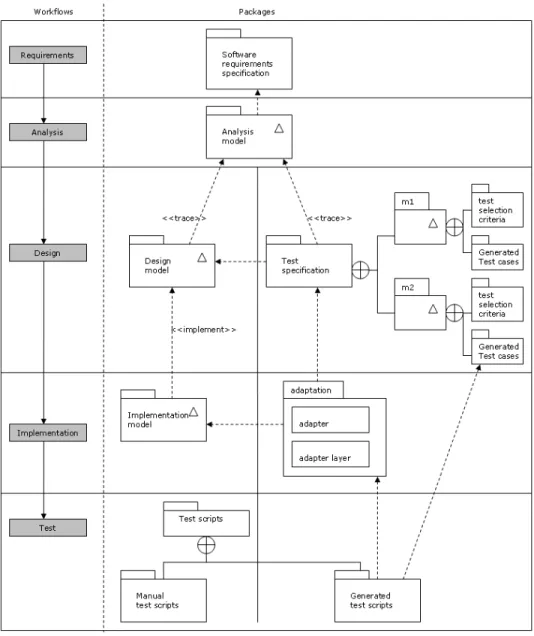
We consider a typical construction iteration of the UP as described earlier. We propose to introduce the MBT activities right after the UP analysis workflow that is in the design process. From the MBT viewpoint, the first activity is the production of a test model. This requires the analysis model to be available.
From this point on, we extend the UP by adding a new artefact for the design workflow, so that two different kinds of model are produced. The first model is the usual design model of the UP, while the second one is a test model. Both are derived from the analysis model and the requirements documents. The design workflow needs to be divided into two parallel processes. A development team will take in charge the execution of the usual design process and a test team will follow a model-based testing process. Those two point of view on the same analysis model may lead to deviation between models. This will be the result of a different or partial interpretation of specification present in the analysis model.
The unified process recommends assigning a team that will go through the entire process for a given functionality, rather than splitting team for a given activity.
For testing activity it’s a good practice to have a dedicated team, first because they must have specific skills and to be relevant a testing model must be in- dependent enough. Obviously a team will be made of workers endorsing a role depending of the workflow or the phase. Team independence during this work- flow is crucial. Any question raised while modeling for test, should be elicited by the system analyst or a stakeholder but not by the development team. A good independence ensures a good accuracy of the generated tests. This parallel process is shown in Fig. 2.
The next workflow in the UP is the implementation. The development team will have to produce an implementation for the design model. Meanwhile the test team will have to produce an adapter to interact with the SUT, that is to implement the generated test cases into executable test scripts. Both develop- ments will occur approximately at the same time and they must be carefully coordinated. The interface must have been well defined for test scripts to inter- act with the SUT. They are called control and observation points. They must be available for the test team to apply scripts and get output from the SUT.
The test workflow needs to be described for each team with more details. This workflow will gather, for the development team, all activities of usual testing;
that are: creating test case, evolving existing test scripts, running tests and re- porting any defects detected.
The goal of this workflow, for the test team, is to generate test scripts from the adaptation layer and the generated test cases. Test cases have been generated during the previous activity using a MBT test generator. Any changes made on the model during the design phase will be integrated to the newly generated test
Fig. 2.Packages produced by the UP extended with MBT
scripts.
The next activity will be the execution of those tests under the system. De- fects will not be reported directly as they can be produced by the model or the implementation (or both). A control of the model must be done before reporting the defect. If the failure is proved to be relative to the implementation, then a good diagnostic can be expressed (issued from our test cases).
3.3 Specializing an analysis model into a test model
We mentioned earlier that UML can be used as the modeling language for the unified process. It can also be used to generate tests (e.g. [OA99]), various works have been done [KR03],[BBM+01],[HIM00],[BL01],[KHC+99] and they all have in common the subset of UML used. Models should represent the system struc- ture and its expected behavior.
The analysis model reflects the system structure with class diagrams. Those di- agrams contain classes, with attributes and operations, and relations between classes. The system behavior will be captured by statecharts and sequence di- agrams. The first one is made of states and transitions linking them. And the second one expresses messages exchange between actors.
An analysis model may contain unnecessary informations (we probably does not want to test every functionality of the system) and in the same time be lacking of crucial informations in regards of our testing process. Those reasons explicit why we need to specialize our analysis model into a new one, the test model.
A test model derives from an analysis model. That means that classes and re- lations (from class diagrams), states and transitions (from statecharts) will be re-used in our test model. However those items cannot be used directly because abstraction is a necessity when modeling for test on a real system [PP05]. This is precisely the step 1 of the process described in section 2.2
Models should not contain every classes of the analysis model, only a subset of classes representing the function to be tested should appear. But on the other side, we need to add information to the test model. The goal of the model is to produce test based on what is expressed. The analysis workflow does not pro- duce a model complete enough. A model should contain class operation with a minimum amount of information about the system behavior. The description can be placed on class diagrams, using pre- and post- conditions, or in state machines using transition effects.
We suggest the use of OCL [WK03] to express those informations. OCL is a formal language, non ambiguous and is part of the UML2.0 specification. Any relevant information expressed in an informal way on the analysis model should be specified using the OCL notation in diagrams used for tests.
4 Case Study: RTAXPM
To illustrate the need for specialization of an analysis model, we will introduce in this section a case study. This is a tax record life cycle of the Geneva State
AFC (fiscal administration). The AFC is using RUP in combination with IBM Rational tools, which gives us a nearly complete and well structured model of the system.
4.1 A taxation life cycle
Fig. 3.Use cases (extract from the model).
The functionality under test for this case study is a taxation life cycle. We only focus on the analysis model, the life cycle is described using three kind of diagram in the AFC model: use case diagram (Fig. 3), statechart diagram (Fig.
4) and class diagram.
Our purpose is to generate tests from this model. We will use all provided di- agrams to produce a model suitable for test. All informal informations will be added on diagrams using OCL. Taking into account the type of diagrams and the formal language used, its availability at the LIFC, we choose to generate test cases with the MBT test generator LEIRIOS Test Generator for UML (LTG)1. The test model have been made with Borland Together Designer 2006 for Eclipse, then exported and processed by LTG.
1 For more information about the model-Based testing tool LTG, see www.leirios.com
Fig. 4.Taxation life cycle (extract from the model).
4.2 Specializing the AFC analysis model into a new test model
In this section we will describe all changes induced by the specialization.
– We add ’taxer’ and ’group leader’ classes. Those classes appear in the model as actor (c.f. Fig. 3), and are issued of the security policy defined for the application framework. This information was clarified by the use case dia- gram and by an explanation of the project manager. In addition the use case explicit that a group leader is the only taxer being able to stamp or suppress a taxation. This will be introduce in the statechart diagram by new states, representing a login and logout from the system.
– We transform informal notation such as ’user allowed to stamp’ and ’stamp needed’, into formal notation:
Fig. 5.Taxation life cycle for MBT.
First the ability for stamping is defined as an attribute oftaxer class.
Added to this, the need for stamp is more complex to introduce. A use case (not included in this paper) describes in an informal way, how to define if a stamp is needed on a taxation. It depends on computation on a taxation record data. This rises a problem of choice:
• we can either put computation rules in the model, it allows the use of exact guard on transitions.
• or we can use a boolean-like value defining if a stamp is needed or not, and leave the computational work to the adaptation layer.
We choose to use a boolean value. We place the following OCL guards in the test model:
[taxer.allow_stamp=true or taxation.stamp_needed=false]and [taxer.allow_stamp=false and taxation.stamp_needed=true]
– We retain all attributes of the analysis class in our ’taxation’ class. They will not be all used for the test of the life cycle but can be useful for other test generation.
– We add, in our ’taxation’ class, operation needed for the transition on the statechart diagram. They will capture the behavior of our taxation life cycle.
It is described by a taxation status (e.g. ’in taxation’, ’controlled’ or ’to stamp’). The taxation status will be our control point for the test oracle.
Figure 5 is the model produced by the specialization of an analysis model into a test model.
4.3 Generated test cases for the taxation life cycle
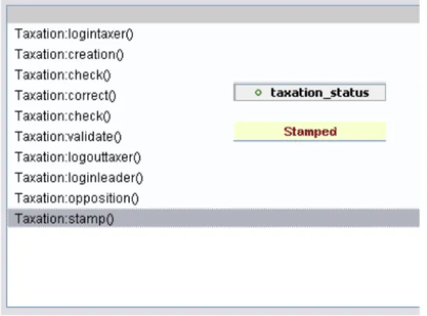
Fig. 6.Test cases for the stamp operation.
For each test target, the LTG tool computes, if possible, one or more test cases. We set up the tool with a depth-first algorithm and a search depth of 10.
For our case study, 16 test cases were produced covering the 9 operations of a taxation.
Figure 6 is a screen shot of a test case example for the ’stamp’ operation and its oracle. This test case is transformed into a test script using the adapter. The produced test script is then ran on the AFC framework through the adaptation layer. The result returned by the framework is compared to the oracle which gives the verdict of our test case.
5 Conclusions
In this paper, we propose to extend the UP with MBT activities. This allow the automatic generation of validation test cases from a test model that inherits from the analysis model. Then, adapters are developed to be used for generating executable test scripts from the abstract generated test cases.
Including MBT into a software engineering process will accelerate its adoption, giving industrials a defined framework to introduce tests from models in their development process. One of the great difficulty of MBT, so far, is to keep the testing model alive. Specifications or design model evolve during a development life cycle and the test model will be useless if not modified. This is where the iterative feature of UP ensure that both models are at an identical state.
The chosen case study at the AFC gives us the first support for this approach, but we need to explore links between analysis, test and design models.
This UP process extended with MBT has been used in the real context of the development of a taxation system at the Geneva State (Switzerland).
The main benefits of the integration of MBT activities into the UP are the reusability of the analysis models to develop the test model, and the automatic generation of validation test cases for the considered application functionalities.
Moreover, the development of the test model, which implies to formalize the expected behavior of the system under test, leads to a direct feedback on the analysis models (and design models) that help their validation.
This integration of MBT activities in well recognized and used software de- velopment process is a key issue for the dissemination of the MBT approach in the software development practices.
Acknowledgments. The authors would like to thank the CTI and Mark Utting for their participation.
References
[Amb05] S. W. Ambler. Introduction to the enterprise unified process. www.
enterpriseunifiedprocess.com. 2005.
[AN03] J. Arlow and I. Neustadt.UML 2 and the Unified Process, Second Edition, Practical Object-Oriented Analysis and Design. Addison-Wesley, 2003.
[BBM+01] F. Basanieri, A. Bertolino, E. Marchetti, A. Ribolini, G. Lombardi, and G. Nucera. An automated test strategy based on uml diagrams. InEricsson Rational User Conference. Upplands Vasby Sweden., 2001.
[BL01] L. C. Briand and Y. Labiche. A uml-based approach to system testing.
In Proceedings of the 4th International Conference on The Unified Mod- eling Language, Modeling Languages, Concepts, and Tools, pages 194–208, London, UK, 2001. Springer-Verlag.
[HIM00] J. Hartmann, C. Imoberdof, and M. Meisenger. Uml-based integration test- ing. InISSTA, 2000.
[KHC+99] Y.G. Kim, H.S. Hong, S.M. Cho, D.H. Bae, and S.D. Cha. Test cases generation from uml state diagrams. InIEEE Software vol. 146, pages 187–
192, 1999.
[KR03] S. Kansomkeat and W. Rivepiboon. Automated-generating test case using uml statechart diagrams. InSAICSIT ’03: Proceedings of the 2003 annual research conference of the South African institute of computer scientists and information technologists on Enablement through technology, pages 296–300, , Republic of South Africa, 2003. South African Institute for Computer Scientists and Information Technologists.
[OA99] J. Offutt and A. Abdurazik. Generating tests from UML specifications.
In Robert France and Bernhard Rumpe, editors, UML’99 - The Unified Modeling Language. Beyond the Standard. Second International Conference, Fort Collins, CO, USA, October 28-30. 1999, Proceedings, volume 1723, pages 416–429. Springer, 1999.
[Obj05] Object Management Group. UML Resource Page. http://www.uml.org, 2005.
[PP05] W. Prenninger and A. Pretschner. Abstractions for model-based testing.
Theoretical Computer Science, 2005.
[UL06] M. Utting and B. Legeard. Practical Model-Based Testing - A tools ap- proach. Elsevier Science, 2006. 550 pages, ISBN 0-12-372501-1. To Appear.
[UPL06] M. Utting, A. Pretschner, and B. Legeard. A taxonomy of model-based testing. Technical report 04/2006, Department of Computer Science, The University of Waikato (New Zealand) http: // www. cs. waikato. ac. nz/
pubs/ wp/ 2006/ uow-cs-wp-2006-04. pdf, 2006.
[WK03] J. Warmer and A. Kleppe.The Object Constraint Language, Second Edition, Getting your models ready for MDA. Addison-Wesley, 2003.