ISSN 1170-487X
A TAXONOMY OF MODEL-BASED TESTING
Mark Utting, Alexander Pretschner
and Bruno Legeard
Working Paper: 04/2006 April 2006
c 2006 Mark Utting, Alexander Pretschner and Bruno Legeard Department of Computer Science
The University of Waikato Private Bag 3105 Hamilton, New Zealand
Mark Uttinga, Alexander Pretschnerb and Bruno Legeardc
aSchool of Computing and Mathematical Sciences, University of Waikato Private Bag 3105, Hamilton, New Zealand
bInformation Security, ETH Z¨urich
ETH Zentrum, IFW C45.2, 8092 Z¨urich, Switzerland
cLEIRIOS Technologies and Laboratoire d’Informatique de l’Universit´e de Franche-Comt´e Besan¸con, France
Model-based testing relies on models of a system under test and/or its environment to derive test cases for the system. This paper provides an overview of the field. Seven different dimensions define a taxonomy that allows the characterization of different approaches to model-based testing. It is intended to help with understanding benefits and limitations of model-based testing, understanding the approach used in a particular model-based testing tool, and understanding the issues involved in integrating model-based testing into a software development process. To illustrate the taxonomy, we classify several approaches embedded in existing model-based testing tools.
1. Introduction
Testing aims at showing that the intended and actual behaviours of a system differ, or at gaining confidence that they do not. The goal of testing is failure detection: observable differences between the behaviours of implementation and what is ex- pected on the basis of the specification.
Model-based testing is a variant of testing that relies on explicit behaviour models that encode the intended behaviour of a system and possibly the behaviour of its environment. Pairs of input and output of the model of the implementation are interpreted as test cases for this implemen- tation: the output of the model is the expected output of the system under test (SUT).
The use of explicit models is motivated by the observation that traditionally, the process of de- riving tests tends to be unstructured, barely mo- tivated in the details, not reproducible, not docu- mented, and bound to the ingenuity of single engi- neers. The idea is that the existence of an artifact that explicitly encodes the intended behaviour can help mitigate the implications of these prob- lems.
Obviously, the model of the SUT must be vali- dated itself (validation is concerned with building
the right system, as opposed to verification that helps with building a system right). This valida- tion is a reciprocal activity: validating the model usually means that the requirements themselves are scrutinised for consistency and completeness.
In terms of model-based testing, the necessity to validate the model implies that the model must be simpler than the SUT, or at least easier to check, modify and maintain. Otherwise, the ef- forts of validating the model would equal the ef- forts of validating the SUT. On the other hand, the model must be sufficiently precise to serve as a basis for the generation of “meaningful” test cases. A model-based testing process must take into account the involved abstractions, and it is likely that omissions in the model mean that these omitted parts cannot be tested on the grounds of the model in question. Throughout this paper, we will use the term “abstraction” to denote both, the deliberate omission of detail and the encap- sulation of detail by means of high-level language constructs (see Section 3.1).
In this survey article, we define model-based testing as the automatable derivation of concrete test cases from abstract formal models, and their execution. Models must be formal enough to al- low, in principle, a machine to derive tests from
1
these models, which is not the case for use case diagrams, for instance. However, the manual derivation of test cases from formal models is also in the realm of model-based testing. We also in- clude in our definition of model-based testing the generation of test infrastructure from models, but we do not concentrate on that aspect in this ar- ticle.
We focus on testing functional rather than non- functional properties—models can also be used for encoding non-functional requirements such as performance, security, or ergonomics, but this is outside of the current mainstream trend in model- based testing. We do not discuss the pragmat- ics of using model-based testing tools, such as their ease of use, speed, interoperability, sup- port for evolving requirements (e.g., generating tests for the subset of the requirements that have changed), or support for traceability (i.e., relating the generated tests back to the model, and per- haps even back to the informal systems require- ments). These issues are important in practice, but are common to many kinds of software engi- neering tools and are independent of the dimen- sions in our taxonomy.
Contribution. The ideas of model-based test- ing, then dubbed specification-based testing, date back to the early Seventies. Recent emphasis on model-based and test-centered development methodologies as well as the level of maturity of technology from the area of formal verification have led to an increased interest in the subject in the past decade. However, there is no compre- hensive overview of the different perspectives on the matter. This paper provides the overview.
It proposes a taxonomy of the various concep- tual approaches to model-based testing. Seven dimensions of model-based testing are identi- fied. The usefulness of the taxonomy is then demonstrated by showing how several existing ap- proaches to model-based testing together with the associated tools can be classified and related.
This paper is oriented towards users of model- based testing. That is, the taxonomy has been designed on the basis of the differentiating factors whenapplyingit for testing. It provides a frame- work for comparing and qualitatively assessing tools and techniques.
Organisation. The remainder of the article is structured as follows. Section 2 introduces the fundamental concepts of model-based testing and introduces our terminology. Section 3 describes the taxonomy, which is used in Section 4 to clas- sify a collection of existing model-based testing approaches and associated tools. Section 5 re- flects on the assumptions underlying model-based testing and discusses empirical evidence. Sec- tion 6 discusses related work and Section 7 draws conclusions, given the expected scope, benefits and limits to model-based testing.
2. Process and Terminology
We use this section to fix terminology and de- scribe the general process of model-based testing (different scenarios are discussed in Section 3.2).
Atest suite is a finite set of test cases. A test case is a finite structure of input and expected output: a pair of input and output in the case of deterministic transformative systems, a sequence of input and output in the case of deterministic reactive systems, and a tree or a graph in the case of non-deterministic reactive systems. The input part of a test case is calledtest input. In general, test cases will also include additional information such as descriptions of execution conditions or ap- plicable configurations, but we ignore these issues here.
A generic process of model-based testing then proceeds as follows (Fig. 1).
Step 1. A model of the SUT is built on the grounds of requirements or existing specification documents. This model encodes the intended be- haviour, and it can reside at various levels of ab- straction. The most abstract variant maps each possible input to the output “no exception” or
“no crash”. It can also be abstract in that it ne- glects certain functionality, or disregards certain quality-of-service attributes such as timing or se- curity (Section 3.1; [1]).
Step 2. Test selection criteria are defined. In general, it is difficult to define a “good test case”
a-priori. Arguably, a good test case is one that is likely to detect severe and likely failures at an ac- ceptable cost, and that is helpful with identifying the underlying fault. Unfortunately, this defini-
Adaptor + Env Test
Selection Criteria
Requirements
Test Case Specification
Model
Verdicts Test
Cases
Test Script
(1) (2)
(3)
(4) (4)
(5−2) (5−1)
SUT
Figure 1. The Process of Model-Based Testing
tion is not constructive. Test selection criteria try to approximate this notion by choosing a subset of behaviours of the model. A test selection cri- terion possibly informally describes a test suite.
In general, test selection criteria can relate to a given functionality of the system (requirements- based test selection criteria), to the structure of the model (state coverage, transition coverage, def-use coverage), to stochastic characterisations such as pure randomness or user profiles, and they can also relate to a well-defined set of faults.
Step 3. Test selection criteria are then trans- formed into test case specifications. Test case specifications formalise the notion of test selec- tion criteria and render them operational: given a model and a test case specification, some au- tomatic test case generator must be capable of deriving a test suite (see step 4). For instance,
“state coverage” would translate into statements of the form “reachσ” for all statesσof the (finite) state space, plus possibly further constraints on the length and number of the test cases. Each of these statements is one test case specification.
The difference between a test case specification and a test suite is that the former is intensional (“fruit”) while the latter is extensional (“apples, oranges, ...”): all tests are explicitly enumerated.
Step 4. Once the model and the test case spec-
ification are defined, a test suite isgenerated. The set of test cases that satisfy a test case specifica- tion can be empty. Usually, however, there are many test cases that satisfy it. Test case genera- tors then tend to pick some at random.
Step 5. Once the test suite has been gener- ated, the test cases arerun(sometimes, in partic- ular in the context of non-deterministic systems, generating and running tests are dove-tailed).
Running a test case includes two stages.
Step 5-1. Recall that model and SUT reside at different levels of abstraction, and that these different levels must be bridged [2]. Executing a test casethen denotes the activity of applying the concretised input part of a test case to the SUT and recording the SUT’s output. Concretisation of the input part of a test case is performed by a component called theadaptor. The adaptor also takes care of abstracting the output (see immedi- ately below).
Step 5-2. A verdict is the result of the com- parison of the output of the SUT with the ex- pected output as provided by the test case. To this end, the output of the SUT must have been abstracted. Consider the example of testing a chip card that can compute digital signatures [3].
Such a chip card is likely to provide functionality that computes random numbers. It seems prob- lematic to actually implement a random number generator at the level of the model—its random numbers will not be those of the chip card. As a consequence, one might conceive the model to provide an abstract command getRandom(n) to provide n random bytes. The output is the ab- stract term rnd(n). Concretization of the input means transforming the input into the bytes the chip card can understand. This input is applied to the chip card which yields n actual random bytes. This result is essentially abstracted into the length of the result, that is, a term rnd(n).
This is where a verdict can be built. Here, the verdict relates to the number of generated bytes only and does otherwise not allow an assessment of the chip card’s random number generator; yet it is useful when the main purpose is to test the procedure of computing a digital siganture.
The verdict can take the outcomes pass, fail, and inconclusive. A test passes if expected and
actual output conform. It fails if they do not, and it is inconclusive when this decision cannot be made (yet).
A test script is some executable code that ex- ecutes a test case, abstracts the output of the SUT, and then builds the verdict. The adaptor is a concept and not necessarily a separate software component—it may be integrated within the test scripts.
Summary. Model-based testing involves the following major activities: building the model, defining test selection criteria and transforming them into operational test case specifications, generating tests, conceiving and setting up the adaptor component (in practice, this takes a sig- nificant proportion of the workload) and execut- ing the tests on the SUT. The model of the SUT is used to validate requirements and check their consistency, as well as to generate test cases.
3. The Taxonomy
This section identifies seven different dimen- sions of model-based testing and discusses the possible instantiations for each dimension. The dimensions are concerned with orthogonal con- cepts yet do influence each other. For instance, if a project uses a continuous model rather than a discrete one, this is likely to limit its choice of modelling paradigm, of test selection criteria, and of test case generation technology.
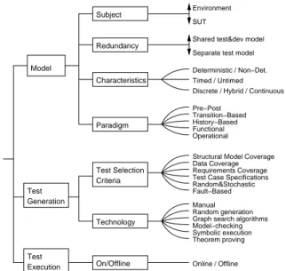
Fig. 2 gives an overview of the taxonomy. The vertical arrows indicate a continuous range of pos- sibilities, the ‘A/B’ alternatives at the leaves in- dicate mutually exclusive alternatives, while the curved lines indicate alternatives that are not nec- essarily mutually exclusive (for example, some tools may use more than one generation technol- ogy, and it is common and desirable to support several kinds of test selection criteria).
3.1. Model Subject
The first dimension is thesubject of the model, namely the intended behaviour of the SUT or the possible behaviour of the environment of the SUT. Most often, both models will be used.
The model of the SUT serves two purposes.
Redundancy
Technology
On/Offline Execution
Test
Test Selection Criteria Paradigm
Generation Test
Subject
Model
Discrete / Hybrid / Continuous
Manual Random generation Graph search algorithms Model−checking Symbolic execution Theorem proving Structural Model Coverage Data Coverage Requirements Coverage Test Case Specifications Fault−Based Transition−Based History−Based Functional Operational
Online / Offline Shared test&dev model Separate test model
Timed / Untimed SUT Environment
Deterministic / Non−Det.
Pre−Post
Random&Stochastic Characteristics
Figure 2. Overview of the Taxonomy
Firstly, it acts as an oracle for the SUT in that it encodes the intended behavior. Secondly, its structure can be exploited for the generation of test cases. The model of the environment is used to restrict the possible inputs to the model. As such, it restricts the set of possible behaviors of the model of the SUT, and in this sense, it acts as a test selection criterion (Section 3.5). Envi- ronment models defined by stochastic user pro- files describe “typical” interactions with a system under test [4,5, Chapter 2], i.e. they describe typ- ical patterns of stimuli to the SUT. Environment models can also be defined by stimuli that exert certain “parts” of a system. This can be done on the grounds of structural requirements on the possible input data, or by restricting oneself to one particular functionality.
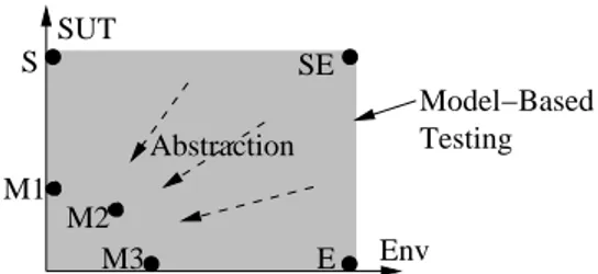
Figure 3 illustrates the possibilities of combin- ing models of the environment and the SUT. The vertical axis shows how much of the behaviour of the SUT is modelled, while the horizontal axis shows how much of the environment is modelled.
The shaded area shows all the possible models that can be used for model-based testing. Let us consider some extreme models.
A model at position S is a model that includes
SUT
Env
Model−Based Testing
E
S SE
M3
Abstraction M1
M2
Figure 3. Model-based testing uses models of the SUT and its environment.
all the details of the SUT but saysnothing about the expected environment. That means that no
“sanity constraints” on the input space of the SUT are imposed.
Model E is the opposite. It has full knowl- edge of the environment that the SUT will be placed in, but knows nothing about the desired SUT behaviour. This means that the model spec- ifies all the legal test inputs, but gives no infor- mation about the expected outputs of the SUT.
The (implicit) expectation that no exception oc- curs would already form an abstract model of the SUT.
Position SE is the most extreme case. Every- thing about the SUT and its environment is mod- elled. This is in general too much detail to be practical; the model would be as complex as the SUT itself. Consequently, they do not occur in practice. Abstraction is essential, so models like M1–M3 are typical for model-based testing.
We have not said how abstraction—obviously a crucial component of model-based testing—can be performed. Prenninger and Pretschner [1]
point out that abstraction can (a) be induced by the modelling language itself—e.g., by not pro- viding any means to cater for security-related issues—or (b) by the modeller who explicitly dis- cards certain information, e.g. timing issues. In practice, both variants are used. Issues that are subject of abstraction in the second sense include the following.
Function Abstraction. The model omits some of the SUT functionality. This is a widely applied abstraction principle. In many cases, cer- tain parts of the functionality are deemed uncriti- cal or so simple that there is no need for explicitly
building a model.
Data Abstraction. This applies to abstrac- tions of both the input and the output. Input abstraction means that the model omits or sim- plifies some inputs of an SUT operation. One example is the abstraction of a set of four-digit PINs in the into two classes, “correct PIN”, and
“incorrect PIN”. Output abstraction means that the model omits or simplifies some outputs of an SUT operation. This simplifies the model, but may also reduce its oracle power. One example is given by the abovementioned model of a ran- dom number generator in a chip card. There are also situations where it is deemed appropriate to abstract input and the desired output into one single signal [6].
Communication Abstraction. This ab- straction principle is exemplified by the ISO/OSI stack where the lower levels are sequences of stim- uli that are abstracted into one single signal at an upper level. Even within one level, sequences of stimuli, or permutations of the stimuli in one se- quence, can be represented by one single signal.
This abstraction is often used in the context of protocol testing where, for instance, it is possible to represent some handshaking in the beginning by one single abstract signal. It is also possible for the model of the SUT to ignore certain signals altogether.
Abstraction from Quality-of-Service.
This general abstraction principle is often used to abstract from concerns such as timing, security, memory consumption, etc. In case of timing, for instance, one might stick to some definition of a logical rather than to actual physical time.
3.2. Model Redundancy Level
Model-based testing can be applied in many different scenarios. Roughly, these differ in the level of redundancy between modelling for test- ing and/or for implementation. In the following, we briefly review two possible scenarios [2]. The first scenario considers one model that is used to generate both test cases and code. The second scenario considers a testing-specific model that is built from the specification documents, while the SUT is implemented manually.
One shared model for test cases and
code. In some cases, executable code can be gen- erated from behavior models. For instance, Mat- lab Simulink block diagrams can be compiled into executable code, and there are some CASE tools that provide generation facilities for both simu- lation and production code from statechart-like formalisms. These facilities suggest that we use the same model to generate tests and also code.
Models for the generation of code have to be very detailed, so are not always ideal for test gen- eration, which is best done with more abstract models. Furthermore, in this scenario, there is no redundancy. In a sense, the system is tested against itself. This means that verdicts beyond
“no exception was thrown” would have to be built manually. One might argue that this missing re- dundancy does not pose any problem since the model is required to be valid, anyway. In prac- tice, however, it is usually the case that problems in both the model and the implementation are detected during testing (e.g., [7]).
Even though this approach is not really suited to test the functionality of a system, it can be used to test the code generator or test generator, and (implicitly) to gain confidence in the assump- tions on the environment that are made in the model.
Separate model for testing purposes. The idea behind this scenario is that the SUT is built manually, based on an existing informal specifi- cation. Furthermore, a test model is manually derived from the specification and used for test generation. Since test cases and code are not gen- erated from the same formal document, the neces- sary redundancy is provided. This approach, one dedicated model for testing inside a more tradi- tional design and coding process, currently is the most common in the literature (e.g. [7–9,3]).
Once an independent test model has been built, it is possible to use that model as detailed speci- fication of the system. It even seems attractive to assign a dual use to these models: they serve as specification and also as a basis for model-based testing—a characteristic that is particularly ap- pealing in development contexts where the im- plementation and the specification (or the model) are designed by different parties. However, test models are rather complex artifacts, so usually
require additional documentation to make them useful as specifications. Moreover, abstractions for testing and specification purposes might be different, which explains why we see a dynamic range between one exclusive model for test and one model for both testing and code generation:
only some parts of the model may be usable for both purposes.
3.3. Model Characteristics
Model characteristics relate to nondetermin- ism, to the incorporation of timing issues, and to the continuous or event-discrete nature of the model.
Nondeterminism occurs in both the model and the SUT. If the SUT exhibits jitter in the time or value domains, this can often be handled when the verdict is built (which might be possible only after all input was applied). If the SUT exhibits genuine nondeterminism, as a consequence of con- currency, for instance, then it is possible that test stimuli as provided by the model depend on prior reactions of the SUT. In these cases, the non- determinism must be catered for by the model, and the test cases, respectively (they are not se- quences anymore but rather trees or graphs). Fi- nally, nondeterminism in the model can be used for testing deterministic systems. One example is given by non-deterministic timeouts to avoid a detailed timing model (e.g., [7, p. 395]).
Evidently, timing issues are particularly rele- vant in the large class of real-time systems. Be- cause of the additional degree of freedom, these systems are notoriously hard to test. Applying the ideas of model-based testing to real-time sys- tems currently is the subject of intense research activities [10].
Finally, in terms of dynamics, models can be discrete, continuous or a mixture of the two (hy- brid). Most work in model-based testing has fo- cused on event-discrete systems, but continuous or hybrid models are often common in many em- bedded systems. Like model-based real-time test- ing, testing continuous systems is the subject of current research [10].
The distinction between different characteris- tics is important, because it impacts the choice of the modeling paradigm, technology for case test
generation, and the interleaving of generating and executing tests.
3.4. Model Paradigm
The fourth dimension is what paradigm and notation are used to describe the model. There are many different modelling notations that have been used for modelling the behaviour of systems for test generation purposes. We group them into the following paradigms, adapted from van Lam- sweerde [11].
State-Based (or Pre/Post) Notations.
These model a system as a collection of variables, which represent a snapshot of the internal state of the system, plus some operations that modify those variables. Rather than defining the opera- tions using code as with programming languages, each operation is usually defined by a precondi- tion and apostcondition. Examples for these no- tations include Z, B, VDM, and JML.
Transition-based Notations. These focus on describing the transitions between different states of the system. Typically, they are graphical node-and-arc notations, like finite state machines (FSMs), where the nodes of the FSM represent the major states of the system and the arcs repre- sent the actions or operations of the system. Tex- tual or tabular notations are also used to specify the transitions. In practice, transition-based no- tations are often made more expressive by adding data variables, hierarchies of machines and paral- lelism between machines. Examples of transition- based notations include FSMs themselves, stat- echarts (e.g. UML State Machines, Statemate statecharts and Simulink Stateflow charts), la- belled transition systems and I/O automata.
History-based Notations. These notations model a system by describing the allowable traces of its behaviour over time. Various notions of time can be used (discrete or continuous, linear or branching, points or intervals etc.), leading to many different kinds of temporal logics.
We also include message-sequence charts and related formalisms in this group. These are graphical and textual notations for specifying se- quences of interactions between components.
Functional Notations. These describe a sys- tem as a collection of mathematical functions.
The functions may be first-order only, as in the case of algebraic specifications, or higher-order, as in notations like HOL. Algebraic specifications tend to be more abstract and more difficult to write than other notations, so they are not widely used for model-based testing.
Operational Notations. These describe a system as a collection of executable processes, ex- ecuting in parallel. They are particularly suited to describing distributed systems and communi- cations protocols. Examples include process al- gebras such as CSP or CCS on the one hand, and Petri net notations on the other hand.
Stochastic Notations. These describe a sys- tem by a probabilistic model of the events and in- put values and tend to be used to model environ- ments rather than SUTs. For example, Markov chains are used to model expected usage profiles, so that the generated tests exercise that usage profile.
Data-Flow Notations. These notations con- centrate on the data rather than the control flow.
Prominent examples are Lustre and the block di- agrams as used, for instance, in Matlab Simulink to then end of modeling continuous systems.
3.5. Test Selection Criteria
The fifth dimension defines the facilities that are used to control the generation of tests. Ac- cordingly, tools can be classified according to which kinds of test selection criteria they sup- port. In the following, we briefly discuss the most commonly-used criteria. Defining the “best” cri- terion is not possible in general; rather, it is the task of the test engineer to configure the test gen- eration facilities and choose adequate test selec- tion criteria and test case specifications.
Structural Model Coverage Criteria.
These criteria exploit the structure of the model, such as the nodes and arcs of a transition-based model, or conditional statements in a model in pre/post notation.
The modelling notation often suggests specific kinds of structural coverage criteria. For exam- ple, with pre-post notations, cause-effect coverage or disjunctive normal form coverage of the post- condition are common coverage criteria, while for algebraic model notations, coverage of the axioms
is an obvious coverage criteria.
For transition-based models, which use explicit graphs containing nodes and arcs, there are many graph coverage criteria that can be used to con- trol test generation. Some of the coverage cri- teria commonly used are all nodes (that is, all states), all transitions, all transition-pairs, and all cycles. The FSM isomorphism-checking methods developed for testing protocols (W-method, Wp- method, D-method etc.) [12,13] are also based on structural coverage of FSM models.
Another set of structural coverage criteria are useful for exercising complex boolean decisions within models. This same need arises in white box testing (code-based testing), so many of the well-known code-based structural coverage crite- ria [14,15, Section 2.1.1] that require certain com- binations of atomic conditions and decisions to take certain values, have been adapted to work on models. Similarly, many data-flow coverage cri- teria [16] for code have been adapted to models.
These criteria can be applied to any modelling notation that contains variables.
Data Coverage Criteria. These criteria deal with how to choose a few test values from a large data space. The basic idea is to split the data space into equivalence classes and choose one rep- resentative from each equivalence class, with the hope that the elements of this class are “equiva- lent” in terms of their ability to detect failures.
For ordered data types, this partitioning is usu- ally complemented by picking extra tests from the boundaries of the intervals. Boundary anal- ysis [17] and domain analysis [18, Chapter 7] are widely accepted as fault detection heuristics and can be used as coverage criteria for test genera- tion (for comparison with random testing, see the respective seminal papers [19–22] and the recent summary by Gaston and Seifert [23]).
Requirements-Based Coverage Criteria.
When elements of the model can be explicitly as- sociated with informal requirements of the SUT, coverage can also apply to requirements. For ex- ample, requirement numbers can be attached to transitions of a UML state machine or to pred- icates within the postconditions of a pre-post model.
Ad-hoc Test Case Specifications. Explicit
test case specifications can obviously be used to control test generation. In addition to the model, the test engineer writes a test case specification in some formal notation, and these are used to deter- mine which tests will be generated. For example, they may be used to restrict the paths through the model that will be tested, to focus the testing on heavily used cases, or to ensure that partic- ular paths will be tested. The notation used to express these test objectives may be the same as the notation used for the model, or it may be a different notation. Notations commonly used for test objectives include FSMs, regular expressions, temporal logic formulae, constraints and Markov chains (for expressing intended usage patterns).
Random and Stochastic Criteria. These are mostly applicable to environment models, be- cause it is the environment that determines the usage patterns of the SUT. The probabilities of actions are modelled directly or indirectly [4,5].
The generated tests then follow an expected us- age profile.
Fault-based Criteria. These are mostly ap- plicable to SUT models, because the goal of test- ing is to find faults in the SUT. One of the most common fault-based criteria is mutation coverage.
This involves mutating the model, then generat- ing tests that would distinguish between the mu- tated model and the original model. The assump- tion is that there is a correlation between faults in the model and in the SUT, and between mu- tations and real-world faults [24,25].
3.6. Test Generation Technology
The sixth dimension is the technology that is used during test generation [26]. In many cases, models of the SUT lend themselves to the man- ual derivation of test cases, which is often the case in model-based development environments where graphical models are built with sophisti- cated CASE tools.
On the other hand, one of the most appeal- ing characteristics of model-based testing is its potential for automation. Recall that the auto- mated generation of test cases necessitates the ex- istence of test case specifications. Given a model of the SUT and the test case specification—
possibly given as an environment model with
further constraints—test cases can be derived stochastically, or by using dedicated graph search algorithms, model checking, symbolic execution, or deductive theorem proving.
Random generation of tests is done by sampling the input space of a system. In the case of reactive systems, finite traces can be selected randomly by sampling the input space and applying it to the model of the SUT in order to infer the expected output part. A random walk on the model may result in test suites with different characteristics.
Random walks can also be performed on usage models given in the form of usage models, and obviously, this results in certain transition prob- abilities for the SUT [27].
Dedicated graph search algorithms include node or arc coverage algorithms such as the Chi- nese Postman algorithm [28], which covers each arc at least once. See a recent compilation [29]
for an overview.
(Bounded) model checking is a technology for verifying or falsifying properties of a system. For certain classes of properties, model checkers can yield counter examples when a property is not satisfied. The general idea of test case genera- tion with model checkers is to first formulate test case specifications as reachability properties, for instance, “eventually, a certain state is reached, or a certain transition fires” (e.g., [30,31]). A model checker then yields traces that reach the given state or that eventually make the transi- tion fire. Other variants use mutations of models or properties to generate test suites.
The idea of symbolic execution is to run an (ex- ecutable) model not with single input values but with sets of input values instead (e.g., [32–34]).
These are represented as constraints. In this way, symbolic traces are generated: one symbolic trace represents many fully instantiated traces. The in- stantiation with concrete values obviously must be performed in order to get test cases for a SUT.
Symbolic execution is guided by test case specifi- cations. Often enough, these boil down to reacha- bility statements as in the case of model checking.
In other cases, test case specifications are given as explicit constraints, and symbolic execution is done randomly by respecting these constraints.
Finally, deductive theorem proving can also be
used for the generation of tests (e.g., [35,36]).
One variant is similar to the use of model check- ers where a theorem prover replaces the model checker. Most often, however, theorem provers are used to check the satisfiability of formulas that directly occur as guards of transitions in state-based models.
3.7. On-line or Off-line Test Generation The last dimension is concerned with the rela- tive timing of test case generation and test exe- cution.
With on-line testing, the test generation al- gorithms can react to the actual outputs of the SUT. This is sometimes necessary if the SUT is non-deterministic, because the test generator can see which path the SUT has taken, and follow the same path in the model (Section 3.3). Off- line testing means that test cases are generated strictly before they are run. Off-line test gen- eration from a non-deterministic model is more difficult, and involves creating test cases that are trees or graphs rather than sequences.
The advantages of off-line testing, when appli- cable, are mostly pragmatic. The generated tests can be managed and executed using existing test management tools, which means that less changes to the test process are required. One can gener- ate a set of tests once, then execute it many times on the system under test (for example, regression testing). Also, the test generation and test ex- ecution can be performed on different machines or in different environments, as well as at differ- ent times. It is also possible to perform a sep- arate test minimisation pass over the generated test suite, to reduce the size of the test set. Fi- nally, if the test generation process is slower than test execution, then there are obvious advantages to doing the test generation phase just once.
4. Classification of Approaches and Tools In this section, we classify some typical model- based testing approaches and associated tools within the dimensions defined in Section 3. The purpose is to show the characteristics of those ap- proaches and the choices made for each dimension in order to target various application domains.
This classification is useful as a snapshot of the state of the art in model-based testing ap- proaches and tools. It also shows that the taxon- omy is useful for discriminating between different approaches to model-based testing.
We consider three approaches to model-based test case generation and two approaches to model-based test input generation in the follow- ing subsections. We discuss a representative tool for each approach, and mention a few similar commercial and academic tools.
4.1. TorX
This is an example for automated test gener- ation from a behaviour model of the SUT. The TorX system is an academic model-based test- ing tool developed in the late nineties [37]. The purpose was to implement the testing theory of conformance relations between models and imple- mentations [38]. This tool is representative of the family of test generation tools based on an Input- Output Labelled Transition System (LTS) model of the system under test. This kind of system manages non-determinism via on-line test gener- ation and execution, and uses ad-hoc test case specifications (called “test purposes” in TorX) as test selection criteria. TorX also provides a batch mode (off line) and some model coverage crite- ria as test selection criteria. Similar tools include TGV [39], STG [40], and AutoLink [41]. A typ- ical target application domain of those tools is telecommunication and protocol systems.
Subject of the model: The model is a behaviour model of the SUT. Some environmental aspects can be taken into account at the level of the model, but also at the level of test selection criteria within the test purposes.
Model redundancy level: The TorX case stud- ies [42,43] show that a dedicated model for test gen- eration was used.
Model Characteristics: TorX manages non- deterministic, untimed, discrete models.
Modelling Paradigm: The underlying paradigm used by TorX is that of LTS; compilers from the LO- TOS and SPIN modelling languages have been devel- oped.
Test Selection Criteria: The TorX test generation algorithm is based on a walk through the state space of the specification. This walk can be done randomly
or controlled by the test purpose, which is anything that represents a set of traces over the model. A test purpose acts as a test case specification and makes it possible to drive the random walk (i.e; the random decisions are constrained by the traces from the test purpose).
Technology: Automated test case generation using on-the-fly state space exploration techniques.
On line/Off line: Both.
4.2. LTG
LEIRIOS Test Generator (LTG) [44], from LEIRIOS Technologies, is a commercially avail- able model-based testing tool. Test cases are gen- erated from a behaviour model of the SUT using model coverage as test selection criteria. LTG accepts two input notations: UML models (class and object diagrams as well as Statecharts, with OCL annotations) and B abstract machines (B is a Pre/Post notation). Some other commer- cially available tools based on model coverage cri- teria are: T-Vec Rave and Test for Simulink, the ATG module of I-Logix, Conformiq Test Gener- ator from Conformiq, Reactis from Reactive Sys- tems. Typical application domains of those tools are reactive systems, embedded software, smart card or e-Transaction applications.
Subject of the model: The input model of LTG is usually an SUT behaviour model–this also provides the oracle for each generated test case.
Model redundancy level: Dedicated testing model.
Model Characteristics:Models must be determin- istic, untimed and discrete and finite.
Modelling Paradigm: LTG supports both State/Transition oriented modelling style (i.e. UML State Machines) and Pre/Post style (i.e. B abstract machines).
Test Selection Criteria: A range of structural model coverage criteria are supported. For state- chart models (i.e. UML State Machines), the criteria include state coverage, all transitions, all extended transitions and all transition pairs. For Pre/Post notations, several kinds of effect coverage are sup- ported (all effects, all pair of effects). In both cases, complex conditions within guards or predicates can be tested more thoroughly using structural coverage criteria like MC/DC. Data values can be chosen on the basis of data coverage criteria: One/many values, random values, boundary values and all values.
Technology: Automated test case generation uses
constraint based symbolic execution of the model and search algorithms. The generated abstract test cases are then translated into executable test scripts using an adaptor component specific to the target test ex- ecution environment.
On line/Off line:LTG uses a batch mode: the exe- cutable test scripts are generated, then can be stored in a configuration management system.
4.3. MatLab Simulink V&V
The Simulink Verification and Validation mod- ule (www.mathworks.com) is aimed at testing con- tinuous and hybrid Simulink models. The main functionalities are traceability from requirements to Simulink / Stateflow models, and model cov- erage analysis.
Subject of the model:Simulink / Stateflow models specify the intended behaviour of the SUT. These are usually composed with environment models.
Model redundancy level: Simulink / Stateflow models are generally used for both test case and code generation.
Model Characteristics: Simulink supports deter- ministic and non-deterministic models, timed models with continuous functions and data types. Hybrid systems are supported as well.
Modelling Paradigm: Simulink / Stateflow com- bine a data flow paradigm (the Simulink function blocks) with a transition-based notation (Stateflow charts).
Test Selection Criteria and Technology: Tests are derived manually and can then be subjected to au- tomated coverage analysis on the level of the model.
For Stateflow charts, the classic state coverage and transition coverage are provided. Simulink blocks rely on dedicated criteria such as lookup table cov- erage, which records the frequency of table lookups in a block. For both kinds of models, other struc- tural coverage criteria are provided for data coverage (boundary values, signal range analysis) and for com- plex boolean decisions (decision coverage, condition coverage, modified condition/decision coverage).
On line/Off line: Test cases are run on the model itself. To run tests on the SUT, one must first record the tests, then adapt them to the SUT interface. This is an off-line approach.
4.4. JUMBL
The J Usage Model Builder Library (JUMBL) [27] is an academic model-based statis- tical testing tool [4] developed at the University
of Tennessee. JUMBL supports the development of statistical usage based models (using Markov chains), analysis of models and the generation of test cases. Test input is generated via a traversal of the usage model on the basis of transition arc probabilities. Therefore, the test cases with greatest probability are generated first. The us- age model does not provide the expected response of the system. Similar tools are the Matelo sys- tem from ALL4TEC and the CleanTest tool from CleanSoft.
Subject of the model:The usage model is a model of the expected environment.
Model redundancy level: The model is a dedi- cated testing model.
Model Characteristics: Models are untimed and discrete. The choice between determinism and non- determinism is not relevant, since only test inputs are generated and SUT behaviour is not modelled.
Modelling Paradigm: JUMBL models are written in the TML language, which is a stochastic notation for describing Markov chain usage models. A Markov chain usage model has a unique start state, a unique final state, a set of intermediate usage states, and transition arcs between states. The transition arcs are labelled by the corresponding event and the probabil- ity of occurrence. Transition probabilities are based on expected use of the SUT.
Test Selection Criteria: Statistical testing provide random and statistical criteria (based on the transi- tion arc probability of the usage model).
Technology: Automated generation of the test inputs using statistical search algorithms and the Markov model.
On line/Off line: The generated test cases need to be translated into a script language of a test execution environment (or executed manually). The JUMBL uses an off-line approach and provides an API to link with test execution environments.
4.5. AETG
Incombinatorial testing the issue is to reduce the—in practice very high—number of possible combinations of input variables to a few “repre- sentative” ones. AETG (Automatic Efficient Test Generator [45]) is a model-based test input gen- erator for combinatorial testing. To reduce the number of test data, it uses a pair-wise algorithm to ensure that all combinations of the data val- ues for each pair of variables are tested. It also
supports all-triples or all-quadruples testing, but the size of the generated test suite grows quickly.
The oracle for each test input has to be provided manually. There are a large number of tools ded- icated to pair-wise testing (www.pairwise.org).
A typical application domain for this approach is testing different configurations, for example de- vice combinations or possible options to configure some product.
Subject of the model: Pair-wise testing (and other n-way testing) uses a simple static model of the input data of the SUT, defining the domains of variables and any unauthorised combinations of values. This is an environment model.
Model redundancy level: The model is dedicated to test input generation only.
Model Characteristics: Models are untimed and discrete. The choice between determinism and non- determinism is not relevant, since AETG models only test inputs, not SUT behaviour.
Modelling Paradigm: There is usually no mod- elling of the behaviour, just the static data domains.
Test Selection Criteria: This class of tools use data coverage criteria such as all-pairs coverage.
Test Case Derivation: Automated generation of the test inputs using n-way search algorithms.
On line/Off line: Off line
5. Assumptions and Evidence
Our description of model-based testing in Sec- tion 1 included several assumptions [46] on its successful deployment. We will now make these assumptions explicit and provide links to some evidence. Because model-based testing can and has been applied in a variety of contexts, it is difficult to come up with large-scale studies that would generalise the positive evidence that we re- port on in this section.
In sum, all assumptions are concerned with both fault-detecting effectiveness and cost- effectiveness of model-based testing when com- pared to competing approaches to quality as- surance, such as traditional forms of testing or reviews and inspections. Recall that testing is about detecting failures whereas reviews target at faults. The assumptions relate to the following.
Models aid requirements. This assumption states that building the model alone helps with
straightening out the requirements.
Existence of an adequate model. This as- sumption is concerned with the trade-off between abstraction and precision. It postulates the ex- istence of an adequate model that can be used effectively for model-based testing. On the one hand, models must be abstract so that they are easy to validate or even amenable to formal ver- ification. On the other hand, they must be suffi- ciently precise so that all the “important” parts can be tested. Usually, additional details are in- troduced at the level of the adaptor components that take care of bridging the different levels of abstraction. That is, complexity is distributed between the model and the adaptor.
Effectiveness. This assumption states that model-based testing does reveal errors in the SUT.
Effort and Quality. Probably the most fun- damental assumption is that the cost of building, maintaining, and validating a model, test case specifications, and the adaptor (with test case generation being a push-button technology), is less than the cost of building, maintaining, and validating a manually designed test suite. It also comes in a form stating that any additional cost is justified by the quality of model-based tests.
Reuse. This assumption relates to testing product lines, or multiple releases of a product with evolving requirements. The assumption is that it will be easier to reuse and adapt the high- level artifacts of model-based testing (models, test selection criteria and adaptor components), than it would be to reuse low-level test scripts or manually designed tests. If this is true, then the cost-effectiveness of model-based testing will be higher for such applications.
We now report on evidence in terms of detect- ing flaws in requirements as well as on evidence in terms of detecting flaws in SUTs. We also cite a few studies that take into account cost- effectiveness.
Flawed Specifications and Requirements Documents. In general, the assumption that building the model alone helps with straighten- ing out the requirements, goes unchallenged. We focus on effectiveness in the context of model-
based testing here and disregard cost. Blackburn et al. [47] describe several stages of the model of a flight guidance control system and show how dif- ferent analysis techniques (reviews, model check- ing, derivation of model traces for manual inspec- tion) help with detecting an increasing number of defects in the model. Pretschner et al. [7] note that building the model reveals a significant num- ber of problems in the specification. However, they also note that remaining omissions in the specification documents are detected only when model-based testing of the SUT was performed.
Flawed SUTs. The evidence that we report on here relates to the assumptions on effectiveness and cost-effectiveness of model-based testing.
Horstmann et al. [48] have compiled some case studies that report on the effective deployment of model-based testing technology. All these studies state that model-based testing helps with detect- ing failures, even if the SUT has been in the field for some time. Comparisons with competing ap- proaches to quality assurance are not provided.
Bernard et al. [8] describe a case study in the domain of smart card testing. Models are spec- ified with the B abstract machine notation and tests are generated using structural coverage of the model. They define a notion of subsumption between test cases that is based on requirements rather than detected failures and show that auto- matically generated model-based tests in general cover existing manual test suites. They show that the time to build the model and generate the tests is significantly lower than the time that was used to hand-craft the tests: 18 as opposed to 30 days.
Farchi et al. [9] report on model-based tests for a POSIX API and parts of some Java garbage collector’s implementation. Models are specified in a variant of the specification language of the model checker Murφand boil down to Mealy ma- chines. Tests are derived on the grounds of re- quirements, i.e., test case specifications are ex- plicitly provided. They can show that model- based tests detect errors that have gone unde- tected before, even in the case of the POSIX API for which a test suite for testing standard confor- mance exists. In this case, model-based testing is reported to take 10 person months as opposed to the 12 person months used for manually generat-
ing the standard test suite.
Pretschner et al. [7] evaluated model-based tests on the grounds of communicating extended finite state machines with a functional language to specify the transitions’ guards and assignment.
Their study is concerned with testing a network controller for automotive systems. The authors contrast different test suites: randomly gener- ated, manually built without model, manually built on the grounds of the model, and auto- matically derived from the model by taking into account test case specifications that reflect the systems “major” operational modes. They doc- ument that (a) modelling itself reveals a num- ber of problems in existing specification docu- ments, (b) that in terms of failure detection, au- tomated model-based tests are approximately as good as manually derived model-based tests, (c) that problems in the system under test are de- tected regardless of whether or not models are used, and (d) that if both problems with the spec- ification and the SUT are taken into account, model-based tests outperform all other kinds of tests, in particular hand-crafted tests that were built without a model. In this study, cost is not taken into account,
Dalal et al. [49] report on evidence obtained with model-based testing deployed in four larger projects. Their approach to model-based test- ing relies on environment (usage) models only:
verdict building must be done manually. They can show that model-based testing detects signif- icantly more errors than other testing approaches.
Clarke [50] and Blackburn et al. [47] report on significant gains in terms of both efficiency and ef- fectiveness when model-based testing is deployed.
Probably for reasons of confidentiality, they do not provide much detail which makes it difficult to fully appreciate the underlying studies.
In sum, ranging over a wide variety of systems, model-based testing has repeatedly been reported to be effective. All case studies report this [51–57, 49,3,6–9,47,24] (list not intended to be complete).
Consequences. We do see good arguments for deploying model-based testing: models help with clarifying requirements specifications, can be used as specifications, and, in addition, can be used to generate tests. This seems partic-
ularly appealing where specification and imple- mentation are done by different parties. However, the cost of building and maintaining the models is clearly not negligible. Whether or not it is cost- effective, and whether or not it outperforms com- peting technologies, remains to be studied. We believe that because test case generation technol- ogy has now matured to a rather impressive ex- tent, researchers in the field can and should tackle this important question. While we acknowledge the difficulties, and while we are clearly aware that not all successful technology has had prior empirical evidence on its side (e.g., OO technol- ogy), we are convinced that more empirical stud- ies are definitely needed.
6. Related Work
The last three decades have seen substantial re- search in the area of model-based testing. Broy et al. have provided a comprehensive overview of research in the field [29]. An early focus of this research was conformance testing between fi- nite state machines; see Gargantini’s review [58].
Binder’s book concentrates on the idiosyncrasies of testing OO software [59].
Tools for test case generation have been sur- veyed by several authors [60,61]. While rather comprehensive, there is no underlying taxonomy.
We chose to not present a full list of tools but rather some typical approaches because there are many commercial and academic tools in the field, and the situation is quickly evolving with new de- velopments and projects. Case studies in model- based testing and empirical investigations have been referenced in Section 5.
Research topics deal with the underlying al- gorithms, theory and technology of model-based testing. The focus of this paper is more on the user perspective of model-based testing. We feel that the field of model-based testing has moved from a research topic to an emerging practice in industry, with some commercial tool support. We are not aware of any taxonomies in this field.
7. Conclusions
The idea of model-based testing is to use ex- plicit abstractions of a SUT and its environ- ment to possibly automatically derive tests for the SUT: the behaviour of the model of the SUT is interpreted as the intended behaviour of the SUT. This approach is particularly appealing be- cause it assigns a threefold use to models: they are used to come to grips with precise require- ments descriptions, they can be used as parts of specification documents, and they can be used to the end of test case generation.
Abstraction is crucial to the approach, and dif- ferent flavors of model-based testing take into ac- count different abstractions: some rely on envi- ronment models only—which makes the gener- ation of test data rather cheap but necessitates a human oracle when test results more detailed than “exception” vs. “no exception” are sought after; some rely on models of the SUT—which solves the oracle problem but is more costly; and many approaches combine the two extremes by using environment models as a basis for test case specifications.
The emerging nature and increasing popular- ity of the field of model-based testing have led to a plethora of publications that, due to a lack of a unifying conceptual framework, are not always easy to put in contrast. The taxonomy of this paper provides this framework. We have demon- strated its utility along the lines of a deliberately partial comparison of different approaches and as- sociated tools. In particular, the taxonomy pre- sented in this paper is intentionally oriented to- ward a model-based testing practitioner point of view.
The technology of automated model-based test case generation in particular has matured to the point where the large-scale deployment of this technology seems possible. We have highlighted the fundamental assumptions that underly its ef- fective use and have provided an overview of existing evidence. In terms of positive failure- detecting effectiveness, the body of evidence is rather large. In terms of cost effectiveness, there is room for further empirical investigations.
In terms of test case generation technology, the
increasing number of tools in both the commercial and academic sectors witness a significant level of maturity that is likely to increase even fur- ther due to industrial demand. In addition to empirical studies, we see the research challenges firstly in the definition of domain-specific test se- lection criteria that, in terms of their fault de- tection power, are empirically underpinned. Sec- ondly, little methodological guidance as to how to build models is currently available, and tool support for building, versioning, and debugging models can be improved. Thirdly, the question of model-based testing for non-functional require- ments such as security or usability, is still an open issue.
REFERENCES
1. W. Prenninger, A. Pretschner, Abstractions for Model-Based Testing, ENTCS 116 (2005) 59–71.
2. A. Pretschner, J. Philipps, Methodological Issues in Model-Based Testing, in: [29], 2005, pp. 281–
291.
3. J. Philipps, A. Pretschner, O. Slotosch, E. Aiglstorfer, S. Kriebel, K. Scholl, Model- based test case generation for smart cards, in:
Proc. 8th Intl. Workshop on Formal Meth. for Industrial Critical Syst., 2003, pp. 168–192.
4. G. Walton, J. Poore, Generating transition prob- abilities to support model-based software testing, Software: Practice and Experience 30 (10) (2000) 1095–1106.
5. J. Musa, Software Reliability Engineering, Au- thorHouse, 2nd ed., 2004.
6. A. Pretschner, O. Slotosch, E. Aiglstorfer, S. Kriebel, Model based testing for real–the in- house card case study, J. Software Tools for Tech- nology Transfer 5 (2-3) (2004) 140–157.
7. A. Pretschner, W. Prenninger, S. Wagner, C. K¨uhnel, M. Baumgartner, B. Sostawa, R. Z¨olch, T. Stauner, One evaluation of model- based testing and its automation, in: Proc.
ICSE’05, 2005, pp. 392–401.
8. E. Bernard, B. Legeard, X. Luck, F. Peureux, Generation of test sequences from formal spec- ifications: GSM 11.11 standard case-study, SW Practice and Experience 34 (10) (2004) 915 – 948.
9. E. Farchi, A. Hartman, S. S. Pinter, Using a model-based test generator to test for standard conformance, IBM Systems Journal 41 (1) (2002) 89–110.
10. K. Berkenk¨otter, R. Kirner, Real-Time and Hy- brid Systems Testing, in: [29], 2005, pp. 355–387.
11. A. van Lamsweerde, Formal specification: a roadmap, in: Proc. ICSE’00, 2000, pp. 147–159.
12. A. Aho, A. Dahbura, D. Lee, M. U. Uyar, An optimization technique for protocol conformance test generation based on UIO sequences and ru- ral chinese postman tours, IEEE Transactions on Communications 39 (11) (1991) 1604–1615.
13. D. Lee, M. Yannakakis, Principles and methods of testing finite state machines — A survey, Pro- ceedings of the IEEE 84 (2) (1996) 1090–1126.
14. H. Zhu, P. Hall, J. May, Software Unit Test Cov- erage and Adequacy, ACM Computing Surveys 29 (4) (1997) 366–427.
15. S. Ntafos, A Comparison of Some Structural Test- ing Strategies, IEEE TSE 14 (6) (1988) 868–874.
16. P. Frankl, E. Weyuker, An Applicable Family of Data Flow Testing Criteria, IEEE TSE 14 (10) (1988) 1483–1498.
17. N. Kosmatov, B. Legeard, F. Peureux, M. Ut- ting, Boundary coverage criteria for test gener- ation from formal models, in: Proc. 15th Intl.
Symp. on SW Reliability Engineering, 2004, pp.
139–150.
18. B. Beizer, Black-Box Testing : Techniques for Functional Testing of Software and Systems, Wi- ley, 1995.
19. D. Hamlet, R. Taylor, Partition Testing Does Not Inspire Confidence, IEEE TSE 16 (12) (1990) 1402–1411.
20. J. Duran, S. Ntafos, An Evaluation of Random Testing, IEEE TSE SE-10 (4) (1984) 438–444.
21. W. Gutjahr, Partition testing versus random test- ing: the influence of uncertainty, IEEE TSE 25 (5) (1999) 661–674.
22. V. Nair, D. James, W. Ehrlich, J. Zevallos, A Statistical Assessment of some Software Testing Strategies and Application of Experimental De- sign Techniques, Statistica Sinica 8 (1998) 165–
184.
23. C. Gaston, D. Seifert, Evaluating Coverage-Based Testing, in: [29], 2005, pp. 293–322.
24. A. Paradkar, Case studies on fault detection effec- tiveness of model based testing generation tech- niques, in: Proc. ICSE 2005 Workshop on Ad- vances in Model-Based Software Testing, 2005.
25. J. Andrews, L. Briand, Y. Labiche, Is mutation an appropriate tool for testing experiments, in:
Proc. ICSE’05, 2005, pp. 402–411.
26. L. L´ucio, M. Samer, Technology of Test-Case Generation, in: [29], Springer LNCS 3472, 2005,
pp. 319–350.
27. S. Prowell, Jumbl: A tool for model-based statis- tical testing, in: Proc. HICSS’03, IEEE, 2003, p.
337.3.
28. M. Kwan, Graphic programming using odd and even points, Chinese Mathematics 1 (1962) 273–
277.
29. M. Broy, B. Jonsson, J.-P. Katoen, M. Leucker, A. Pretschner (Eds.), Model-Based Testing of Reactive Systems, no. 3472 in LNCS, Springer- Verlag, 2005.
30. A. Offutt, S. Liu, A. Abdurazik, P. Ammann, Generating test data from state-based specifica- tions, J. Software Testing, Verification and Reli- ability 13 (1) (2003) 25–53.
31. H. Hong, I. Lee, O. Sokolsky, H. Ural, A Tem- poral Logic Based Theory of Test Coverage and Generation, in: Proc. TACAS’02, 2002, pp. 327–
341.
32. A. Pretschner, Classical search strategies for test case generation with Constraint Logic Program- ming, in: Proc. Formal Approaches to Testing of Software, 2001, pp. 47–60.
33. B. Marre, A. Arnould, Test Sequences Generation from LUSTRE Descriptions: GATEL, in: Proc.
15th IEEE Conf. on Automated SW Engineering, 2000, pp. 229–237.
34. S. Colin, B. Legeard, F. Peureux, Preamble com- putation in automated test case generation us- ing Constraint Logic Programming, J. Software Testing, Verification and Reliability 14 (3) (2004) 213–235.
35. J. Dick, A. Faivre, Automating the generation and sequencing of test cases from model-based specifications, in: Proc. 1st Intl. Symp. of For- mal Methods Europe: Industrial-Strength Formal Methods (FME 1993), Vol. 670 of LNCS, 1993, pp. 268–284.
36. S. Helke, T. Neustupny, T. Santen, Automating test case generation from Z specifications with Is- abelle, in: Proc. 10th Intl. Conf. of Z Users, Vol.
1212 of LNCS, 1997, pp. 52–71.
37. J. Tretmans, E. Brinksma, Cˆote de Resyste – Au- tomated Model Based Testing, in: Progress 2002 – 3rd Workshop on Embedded Systems, 2002, pp.
246–255.
38. J. Tretmans, Test Generation with Inputs, Out- puts and Repetitive Quiescence, Software – Con- cepts and Tools 17 (3) (1996) 103–120.
39. C. Jard, T. J´eron, TGV: theory, principles and al- gorithms, J. Software Tools for Technology Trans- fer 7 (4) (2005) 297–315.
40. D. Clarke, T. J´eron, V. Rusu, E. Zinovieva, STG:
A symbolic test generation tool, Vol. 2280 of Springer LNCS, 2002, pp. 470–475.
41. B. Koch, J. Grabowski, D. Hogrefe, M. Schmitt, AutoLink – a tool for automatic test generation from SDL specifications, in: Proc. IEEE Intl.
Workshop on Industrial Strength Formal Speci- fication Techniques (WIFT 1998), 1998, pp. 114–
127.
42. L. du Bousquet, S. Ramangalahy, S. Simon, C. Viho, A. Belinfante, R. de Vries, Formal test automation: The conference protocol with TGV/Torx, in: Proc. TestCom’00, 2000, pp. 221–
228.
43. R. G. de Vries, A. Belinfante, J. Feenstra, Au- tomated testing in practice: The highway tolling system, in: Proc. TestCom’02, 2002, pp. 219–234.
44. F. Bouquet, B. Legeard, F. Peureux, E. Tor- reborre, Mastering Test Generation from Smart Card Software Formal Models, in: Proc. Intl.
Workshop on Construction and Analysis of Safe, Secure and Interoperable Smart devices, Vol. 3362 of Springer LNCS, 2004, pp. 70–85.
45. D. Cohen, S. Dalal, M. Fredman, G. Patton, The AETG System: An approach to testing Based on Combinatorial Design, IEEE TSE 23 (7) (1997) 437–444.
46. A. Pretschner, Model-Based Testing in Practice, in: Proc. Formal Methods, Vol. 3582 of Springer LNCS, 2005, pp. 537–541.
47. M. Blackburn, R. Busser, A. Nauman, Why model-based test automation is different and what you should know to get started, in: Proc.
Intl. Conf. on Practical Software Quality and Testing, 2004.
48. M. Horstmann, W. Prenninger, M. El-Ramly, Case Studies, in: [29], 2005, pp. 439–461.
49. S. R. Dalal, A. Jain, N. Karunanithi, J. M.
Leaton, C. M. Lott, G. C. Patton, B. M.
Horowitz, Model-based testing in practice, in:
Proc. ICSE’99, 1999, pp. 285–294.
50. J. Clarke, Automated Test Generation from Be- havioral Models, in: Proc. 11th Software Quality Week, 1998.
51. H. Kahlouche, C. Viho, M. Zendri, An indus- trial experiment in automatic generation of ex- ecutable test suites for a cache coherency proto- col, in: Proc. IFIP TC6 11th Intl. Workshop on Testing Comm. Systems, 1998, pp. 211–226.
52. A. Belinfante, J. Feenstra, R. d. Vries, J. Tret- mans, N. Goga, L. Feijs, S. Mauw, L. Heerink, Formal test automation: A simple experiment,
in: Proc. 12th Intl. workshop on Testing of Com- municating Systems, 1999, pp. 179–196.
53. L. Fournier, A. Koyfman, M. Levinger, De- veloping an Architecture Validation Suite—
Application to the PowerPC Architecture, in:
Proc. 36th ACM Design Automation Conf., 1999, pp. 189–194.
54. J. Shen, J. Abraham, An RTL Abstraction Tech- nique for Processor Micorarchitecture Validation and Test Generation, J. Electronic Testing: The- ory&Application 16 (1-2) (1999) 67–81.
55. J. Dushina, M. Benjamin, D. Geist, Semi-formal test generation with Genevieve, in: Proc. 38th conf. on Design automation, 2001, pp. 617–622.
56. D. Clarke, T. J´eron, V. Rusu, E. Zinovieva, Au- tomated Test and Oracle Generation for Smart- Card Applications, in: Proc. E-smart, 2001, pp.
58–70.
57. I. Craggs, M. Sardis, T. Heuillard, AGEDIS Case Studies: Model-Based Testing in Industry, in:
Proc. 1st Eur. Conf. on Model Driven Software Engineering, 2003, pp. 129–132.
58. A. Gargantini, Conformance Testing, in: [29], 2005, pp. 87–111.
59. R. V. Binder, Testing Object-Oriented Systems:
Models, Patterns, and Tools, Addison-Wesley, 1999.
60. A. Hartman, AGEDIS - Model Based Test Gen- eration Tools (2002).
61. A. Belinfante, L. Frantzen, C. Schallhart, Tools for Test Case Generation, in: [29], Springer LNCS 3472, 2005, pp. 391–438.