TOWARDS A WORKFLOW LANGUAGE FOR SOFTWARE ENGINEERING
Gregor Grambow and Roy Oberhauser Computer Science Dept.
Aalen University Aalen, Germany
{gregor.grambow, roy.oberhauser}@htw-aalen.de
Manfred Reichert
Institute for Databases and Information Systems Ulm University
Ulm, Germany manfred.reichert@uni-ulm.de ABSTRACT
Software development processes are broadly used by software providers to ensure the quality and reproducibility of their development endeavors. These processes are typically abstractly defined, individually interpreted by individuals, and manually executed, making governance and compliance difficult.
Additionally, process tailoring, reuse, exchange, and any IT-based automation or guidance at the more practical lower level workflows is hindered or more burdensome without a common language for expression. Automated guidance and highly integrated process support holds potential for retaining process-centered advantages while reducing hindrances. In this paper, work on a language for the description of software engineering processes is presented. It unifies the abstract specification and documentation of processes with automated process enactment support, while, in turn, fostering reusability and tailoring of these processes. For enactment, various workflow management systems can be chosen whose models are automatically generated. The approach shows promise for enabling IT process support in the software engineering domain while supporting the exchange and objective comparison of enactable processes and practices.
KEY WORDS
Process modeling, process enactment, workflow management, process-centered software engineering, software engineering environments, process reuse, process language.
1. INTRODUCTION
Various industries utilize IT supported processes for structuring activities and making their sequence reproducible [1][2]. Yet the application of such IT process support to the software development industry presents challenges due to the high degree of uniqueness and dynamicity, often resulting in very general and abstract process models and specifications. These processes are typically defined via documentation devoid of live, low- level enactment support or automated process governance that for instance could foster reproducibility and traceability.
To address these challenges, process aware information systems (PAIS) [3] or workflow management systems (WFMS) [4] could be considered. They provide automated governance of the activities defined as part of a process and thereby enable automated guidance, monitoring, and enforcement of the process. Furthermore, they facilitate the integration of the process into everyday work since the activities are automatically aligned with the process. However, this connection between the abstract process and the executed workflow is rarely established in the software engineering (SE) domain. One reason for this is the adolescence of this discipline and its dynamicity. Process research in this domain is still immature, process models change rapidly, and the processes require comprehensive tailoring to be usable.
Modeling these abstract processes directly in a WFMS is burdensome and error-prone since the processes must be translated into tailored executable workflows requiring additional modeling work. If the process descriptions were machine readable, automated transformations for different WFMS could be defined. Any reduction in the effort and error proneness would reduce associated costs that could encumber greater adoption of PAIS in SE.
A software engineering workflow language (SEWL) is thus proposed to assuage the above automation hindrances. To unify process and workflow in the SE domain, several requirements must be satisfied.
Transformation of the processes to common WFMS should be supported with a clear mapping of process elements to workflow elements. To foster exchange and reusability, the process models should be extensible, modularly structured, and be able to capture recurring procedures.
The remainder of this paper is organized as follows:
the next section presents a review of related work. A solution is defined in Section 3, supported by a concrete scenario in Section 4, and technically concretized in Section 5. Section 6 presents initial performance and scalability measurements followed by the conclusion.
2. RELATED WORK
Approaches exist that focus on bridging the gap between different process models via transformation. The approach presented in [5] provides a mapping between two metamodels in order to bridge the gap between abstract
processes and concretely executable workflows. These are the Software Process Engineering Metamodel (SPEM) and the UML Extended Workflow Metamodel (UML- EWM), whereas a mapping for central concepts of the models has been defined. [6] considers the transformation of SPEM processes to the business process modeling notation (BPMN). The transformation utilizes a maths- based notation to formally specify both specifications as well as the transformation itself. A mapping from SPEM to the XPDL standard is established in [7], incorporating the mapping of the metamodels itself as well as the transformation algorithm and the corresponding transformation engine. The xSPEM [8] approach has two goals: the possibility of validation of processes defined in SPEM and the executability of these processes. The first goal is achieved via a transformation to Petri Nets and the use of formal tools like model checkers. The second is achieved by a transformation to BPEL, whereby the authors already identified several drawbacks including the loss of semantics and the need to manually complete the processes for execution. In contrast to SEWL, none of these considers enactment support or applicability to real world project scenarios. Their focus is the transformation of models.
In support of enactability, several approaches address transformations of process descriptions. In [9] a mapping from a subset of BPMN and UML Activity Diagrams to BPEL is proposed. This is done in three steps: control- flow constructs are translated into precondition sets, which are translated into ECA rules. These rules, in turn, are translated into BPEL. The approach presented in [10]
also takes UML Activity Diagrams and BPMN into account. Both are analyzed and a special workflow profile for the Activity Diagrams is proposed as well as a transformation to a subset of BPMN. A central goal of these process representation transformation approaches is the facilitation of process definition and enactment enabling a model-driven approach for process management. While these approaches focus on supporting enactability, they only provide model transformations and do not provide any means of execution support.
SEWL not only bridges the gap between abstract processes and concrete workflows but also provides an environment for real integration of the processes into daily operations.
Considering the reuse of pattern-based process fragments, [11] seeks to improve integration, changeability and evolution of processes by proposing a modularly structured process framework that integrates a process patterns concept. [12] presents a set of generative patterns to shape a new organization and its software development processes. In [13] a patterns-based process model is proposed that consists of three components: a well-defined hierarchical result structure to capture the desired results of various development activities, a set of consistency criteria, and a set of process patterns. The above define abstract models or metamodels that are unsuitable for execution. These approaches offer reusable
process patterns. In contrast, SEWL seeks to provide comprehensive process support including process patterns integration as well as bridging the gap between abstract process areas and the actual execution.
3. SOLUTION APPROACH
A holistic solution would not only provide comprehensive support for process definition as well as workflow enactment, but also provide automated guidance to developers and enable process pattern reuse and exchange.
3.1 Context
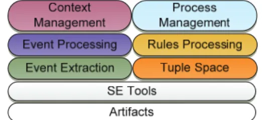
This contribution relies on the infrastructure provided by the Context-aware Software Engineering Environment Event-driven framework (CoSEEEK) [14]. Figure 1 illustrates the different framework components summarized below.
Figure 1: CoSEEEK Conceptual Architecture Artifacts is a placeholder for various artifacts processed in a software development project, e.g., source code or documentation artifacts. Their processing mostly involves different heterogeneous SE Tools such as integrated development environments or version control systems. To enable CoSEEEK to be aware of these tools and artifacts, the Event Extraction module is utilized. This module employs Hackystat [15] sensors that are integrated into various SE Tools, generating events for activities executed in these tools. To enhance these events with greater semantic value, the Event Processing module applies complex event processing (CEP) [16]. Thus, multiple basic events are aggregated into larger events indicating the activities of users. The Rules Processing module contains a rule engine to automatically execute actions based on such events. The communication of all modules is based on a loosely-coupled event architecture, an XML implementation of the tuple space paradigm [17], and the use of web services.
To be able to cope with the complexity and dynamicity of the software development process, activity governance is managed by two modules: the Context Management module and the Process Management module. The Context management module employs semantic technology to enable reasoning over the information aggregated by other modules (e.g.,
information about external tools or users). The use of such technology, in particular ontologies, is advantageous [18]:
it provides a vocabulary including logical statements about the modeled entities and their relations as well as a taxonomy for these entities. Well-structured ontologies also enable automated consistency checking and enhance interoperability between different applications and agents, furthering knowledge sharing and reuse.
The Process Management module utilizes PAIS technology. Due to the dynamic nature of SE, the module must be able to deal with ad-hoc process changes during runtime in order to keep processes consistent with reality.
Therefore the AristaFlow BPM suite (formerly ADEPT2) [3] was used. It allows runtime dynamic process changes while still guaranteeing the structural and behavioral soundness of the modified process instance.
Both of the latter modules are tightly integrated:
process management concepts are enhanced with information in the ontology. Thus, it is possible to leverage context information for automated workflow adaptations, bridging the gap between defined processes and actual activity execution. Guidance is not only provided for workflows, which are part of SE processes, but also for the dynamic activity flows that are extraneous to these processes [19]. The combination of context information and dynamic processes also enables the integration of process management with quality management by fully automating the integration of quality assurance activities into running workflows while meeting current time and resource constraints [20].
A plugin for the Eclipse IDE, Visual Studio, and browser access provide GUI-based process navigation, automated assignment and task guidance, coordination, and notification directly to software engineers within both the overall process and the concrete instantiated workflow while avoiding any WFMS-specific GUI.
3.2 Analysis
Any comprehensive support for both process specification and enactment includes not only the presence of a consistent modeling language that can cover the entire process lifecycle and its workflows, but also a holistic integration of the process into SE environments. Thus, an SE process modeling language must also support various environmental tools, their sensors, and allow for integration changes. For reusability, a facility for easy exchangeability of process fragments or the underlying enactment technology is required.
For specifying abstract SE process definitions, the SPEM was initially considered due to its proliferation.
However, since SPEM was not developed for automated enactment, it was not ideally suited for that purpose.
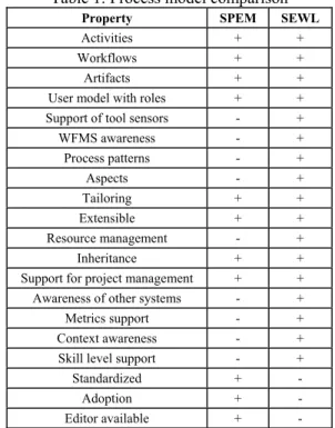
Moreover, additional features or properties desirable in a software engineering workflow language (SEWL) as depicted in Table 1 were also absent, leading to the proposal of a SEWL.
While both models support the basic concepts of activities, users, workflows, inheritance and artifacts, the artifact support of a newly defined model in the CoSEEEK context could foster better integration of these into the development environment. For process adaptability, a SEWL has also advantages since it cannot only support predefined tailoring but also so-called process aspects, which enable unforeseen changes to the model. The SEWL can also provide support for process patterns, which can integrate the process seamlessly into the development environment. This can be done utilizing the context-awareness of CoSEEEK as well as support for tools and restricted resources. Both models are capable of supporting project management by specifying activity durations, but the SEWL can also define metrics to assess process quality during runtime. Another advantage of a SEWL is the awareness of concrete WFMS, which makes it possible for the process engineer to incorporate certain settings into the process description such as, e.g., a mapping of the role/user model to the model of the used WFMS. In contrast, the main advantages of the SPEM are its standardization, proliferation, and editor support.
Table 1: Process model comparison
Property SPEM SEWL
Activities + + Workflows + +
Artifacts + + User model with roles + +
Support of tool sensors - + WFMS awareness - + Process patterns - +
Aspects - +
Tailoring + + Extensible + + Resource management - +
Inheritance + + Support for project management + +
Awareness of other systems - + Metrics support - + Context awareness - + Skill level support - +
Standardized + -
Adoption + -
Editor available + -
AristaFlow was chosen for the concrete enactment due to its existing integration into CoSEEEK. To demonstrate support for workflow heterogeneity in the language, the YAWL WFMS [21] was also integrated.
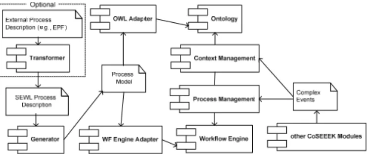
3.3 Process Transformation and Execution Concept To provide as much flexibility as possible, the concept utilizes several components as depicted in Figure 2.
Figure 2: Conceptual Components
The main component in processing of the SEWL is the Generator. It takes an XML description of a SEWL process as input and creates an internal process object model. The transformation of this model into different representations is done by different Adapters. One Adapter creates the required instances in the ontology, while other Adapters create the workflow template in the target workflow engines. Both the ontology and the target workflow engine are utilized and managed by CoSEEEK modules, namely the Process Management module and the Context Management module, which communicate among themselves and with other CoSEEEK modules via events. Since the SEWL is new and not standardized, support for process specification in another notation or tool was also integrated. Therefore, a Transformer module is used to transform the external process description into a SEWL process description.
3.4 SE Workflow Language
The basic concepts of the SEWL will now be described and then exemplified in Section 4. A workflow is specified based on the Process, Element, and Attribute concepts. Process is used as container for all other concepts. Each element of the workflow structure is defined by the Element, which can have different Attributes. By utilizing inheritance, it is possible to hierarchically specify different elements of a workflow.
The SEWL already features standard elements that are defined in an abstract base process from which newly defined processes inherit. Figure 3 shows these elements.
Container is an abstract base class for elements that can contain child elements. Flow is the base class for element flow control, which has different subclasses for sequential and parallel flows.
Figure 3: Element Inheritance Structure
The SEWL features a user model to specify which users execute which activities. It is applied via the concepts Role, User, Group, and Mapping, which all inherit from the base concept of the Resource. Roles serve as placeholders for users or teams when it is not yet known who will execute an activity. Users are members of the project who can occupy certain Roles. Groups are used to aggregate an arbitrary numbers of Roles, Users, or other Groups. The SEWL is designed to be transformable into other models of various target workflow engines that have diverse realizations of a user concept. Thus, Mapping enables the process engineer to map the resources to resources of the desired target engine.
To support the specification of SE processes, the SEWL also includes concepts for artifacts and tools.
Artifacts can have different ArtifactTypes and utilize inheritance to enable hierarchical specification of different Artifacts. The same applies to Tools, which are used to capture the development environment.
An important aspect of process models is the adaptability to the needs and situations of the organizations that use them. The SEWL takes account of this via the concepts of Tailoring and Aspect. Tailoring enables the process engineer to apply predefined change operations on Elements. Examples for such a Tailoring include the changing of an Attribute of the Element or the usage at another position in the process. In contrast to the Tailoring, which is predefined and static, the Aspect allows for unforeseen changes to every process.
Best practices must be captured on a relatively concrete activity level, and to facilitate their reusability as well as to foster process integration in the development environment of the concrete user in conjunction with the contextual features of CoSEEEK, the SEWL contains a Pattern concept. Patterns can be viewed as small processes describing concrete activities such as merging newly developed source code into a repository. It is possible to specify which Artifacts and Tools a Pattern requires. To promote a higher degree of automatism, Patterns make use of complex events that are detected and processed by CoSEEEK.
4. OPERATIONAL SCENARIO
For illustration purposes, the main features will now be described with a scenario. A multi-national company seeks to introduce a new development process in all of its branch offices. Initially, SEWL provides process engineers with support for the creation of a description of the process. Templates for standard development processes like OpenUP or Scrum are already in place.
Utilizing the inheritance and tailoring features of SEWL, the process is tailored to the specific needs of the company, e.g., OpenUP is to be used, but additional roles (e.g., a test manager) are required. For that case, the new process inherits the OpenUP template. Then only the role
has to be created and, via tailoring rules, the activities that shall be executed by the test manager can be subjected to the new role. Localization of the process for the branch offices can be done in the same way by creating a localized version of the process. All localized processes inherit from the company’s standard process and only contain the translations, which are injected via Tailorings.
A global company with multiple branch offices also often requires working with virtual teams that are spread throughout multiple countries. Activities processed by such teams can require additional coordination effort.
Knowing this, a process engineer can define a group comprising all team members and a Coordination Aspect that injects a communication activity to be executed by such groups e.g., at the beginning of each iteration.
SEWL can also support the process engineers with different degrees of process documentation. If only basic process documentation is required, SEWL can provide this utilizing its modular architecture with its multiple adapters. Thus, other process-related documents could be created directly from the SEWL process specification. To exemplify this, a documentation adapter was implemented to automatically generate process related documentation alongside the executable workflow. Figure 4 shows a part of that documentation.
Figure 4: Documentation Adapter
The adapter generates html documents for the workflows. On the left side, a navigation column allows the process structure to be browsed while a graphical representation of the selected workflow is shown. These html documents can serve as a skeleton process documentation, providing the project members with navigability information that can be enhanced with textual descriptions. If more comprehensive process documentation is required, the process can be created and documented in specialized other formats and then transformed into a SEWL representation utilizing its transformers. As a demonstration of this capability, a transformer for the Eclipse Process Framework (EPF) [22] was created to allow EPF to be used as a comprehensive process model with documentation, while automatically transforming the execution relevant parts to SEWL.
The abstraction and exchangeability of the workflow enactment system is another advantage of SEWL. Thus, all process specification and documentation remains invariant while only the workflows for the target system need be generated. For instance, a process engineer can
substitute a different enactment system for which a transformer exists (YAWL, AristaFlow) relatively quickly without additional effort.
The concept of the process patterns SEWL provides in conjunction with CoSEEEK’s sensor and context architecture can also support process specification and enactment. For example, a specialized merge process for source code files has to be followed in the described company. That process can impose certain documentation activities with certain tools based on the outcome of the merge process. This whole process can be encapsulated in a process pattern and then be easily integrated in the tailored OpenUP the company uses. Since patterns are connected to the CEP architecture, they also allow for further automation of the process. A sensor in the source control system can determine the outcome of the merge process. Based on the generated event containing this information, the pattern can automatically choose the proper follow up activity and inform CoSEEEK about the state via another event generated by the pattern. Not only the awareness of tools can be beneficial here, but also the association to the CoSEEEK project context, which can provide information related to the execution. For instance, certain activities can already be specified at the process level to only be executed by experienced software engineers, enabling the system to guard that condition during execution or even perform automated rescheduling.
5. SEWL IMPLEMENTATION
This section concretizes the presented concept and relevant implementation details are described.
5.1 Procedure
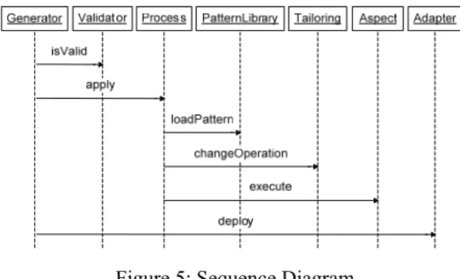
The procedure for converting and applying a SEWL process is illustrated via a simplified sequence diagram in Figure 5.
Figure 5: Sequence Diagram
The Generator first uses the Validator to validate the input XML file against an XSD file, which was created for the SEWL. If the file is valid, the Process class is
called to create an in-memory process representation from the XML file. This class, in turn, interacts with the PatternLibrary to load Patterns as needed and applies Tailorings and Aspects to the process. Finally, the different Adapters are called to create the target representations of the process. The Adapters that interact with WFMS preferably use the APIs of those systems to exploit their built-in correctness checks.
5.2 Language Elements
Due to space limitations, this section explains how selected parts of the SEWL are realized. For most parts of the language, the definitions of the concepts and the concrete instances of these have been separated as shown in Figure 6 and Figure 7.
The central building block of a process is the Element that is defined by the ElementDefinition as depicted in Figure 6.
Figure 6: ElementDefinition
Each ElementDefinition has standard properties that allow specifying the name of the element as well as information on inheritance regarding this element. These are the element from which the current element inherits and if inheritance or instantiation of the current element is allowed. Elements can be extended via custom attributes;
therefore, the ElementDefinition comprises the two collections attributes, which is used for general-purpose attributes, and structure, which is used to store information that is used by the adapters. Examples for structure attributes include tailoring to specify if an element can be changed by Tailorings, or Aspects and children to specify if the element can have child nodes.
Via rules it can be defined which kinds of child nodes are allowed for the current element. The elements sequence, parallel, if, and loop are always allowed. Finally, input and output allow for the specification of input and output artifact types of the current element.
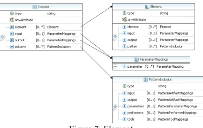
The concept of the Element describes an instance of a process element, as depicted in Figure 7. An Element references an ElementDefinition via the type property. It can include an arbitrary number of other Elements. Via the ParameterMappings for input and output of the Element, an Artifact instance is mapped to a local variable of the Element. Patterns can be integrated within an Element. This is done by the PatternInclusion, which maps all needed parameters to the included Pattern.
As with most other elements, Patterns can use inheritance utilizing the properties base, abstract and final, which have been shown for the Element. A Pattern can also be extended via Attributes and has input and output parameters. Furthermore, it can define special Tool and Artifact types and a set of required Tools. Each Pattern has a defined workflow and communicates with the event infrastructure of CoSEEEK. Thus, the workflow of a Pattern does not need explicit user interaction, but runs on the basis of an automatically detected user environment event, e.g., switching to the debug perspective in the IDE. Currently, Patterns are realized via separate XML files and require a predefined workflow template in the target workflow engine. Listing 1 shows a simplified version of an example Pattern.
Figure 7: Element
The Pattern ‘Merge Files Manually’ is applied for the merging of two source code files by a user. The workflow starts upon receiving a complex event indicating the manual merge process from the CoSEEEK infrastructure.
After that, two parallel activities are to be executed, one for the comparing of the files and one for the actual merge process. Both activities are automatically finished again by complex events, whereas the ‘Merge Finish’ event contains information on the outcome of the process.
Dependent on that event, the pattern can generate a new event informing other modules about a merge error.
Listing 1: Pattern Example
<pattern name="MergeFilesManually">
<workflow>
<wait for="MergeManualStart"/>
<parallel>
<wait for="MergeDone" storeResult="var1"/>
<wait for="CompareDone"/>
</parallel>
<if variable="var1" equals="true">
<send event="MergeError"/>
</if>
</workflow>
</pattern>
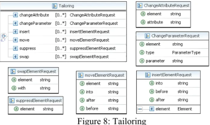
To be able to match predefined processes to different situations, the SEWL features the concepts of Tailoring and Aspect. It can be specified for each Element if such
changes are allowed. Tailoring provides the different predefined changes depicted in Figure 8.
The ChangeAttributeRequest is used for changing the value of an Attribute belonging to an Element. By this means, e.g., the language of the Attributes can be changed to enable different translations of the process without modifying it. Via the ChangeParamterRequest, the input and output Artifacts of an Element can be changed, whereas the replacement Artifacts must be of the same type as the initial ones. The InsertElementRequest allows for the integration of new Elements into the process.
These can be integrated before, after another Element, or as the last child node of an Element. The MoveElementRequest provides the same operations for insertion, but applies these on an Element that is already part of the process. To remove an Element and all of its child nodes, the SuppressElementRequest is utilized. It is also possible to swap two Elements via the SwapElementRequest. All of these operations feature correctness checks, e.g., to ensure that Artifacts are not read by an Element before it exists.
Figure 8: Tailoring
The change operations of Tailorings are fixed and dependent on the process to be changed via inheritance. In contrast, Aspects allow change logic that can be applied without prior knowledge of the process using the Aspect interface. An example for the usage of Aspects is the integration of an additional activity after certain Elements of any process, e.g., to add an assessment meeting after each iteration.
6. MEASUREMENTS
This section provides initial performance and scalability measurements of the SEWL implementation. Future work will include studies in conjunction with industrial partners of this project. In these studies, the CoSEEEK framework will be implemented and practically used at the partner companies and thus the usability and real world applicability of the whole framework including SEWL will be validated.
The test configuration for the measurements consisted of a computer with an Intel Core2Duo E8500 with 8 GB DDR2-800 RAM and three WD6400AAKS hard disks in
a Raid 0 configuration. The software used was Windows 7 Professional x64, Java 1.6.20 (x64) and 1.5.0.22 (x64), Scala 2.7.7 for XML processing, AristaFlow 1.0.0 r71, YAWL 2.1, and Protégé 3.4.4 that generated the classes for ontology access utilizing the Jena API [1]. Five consecutive measurements with the JVisualVM profiler were averaged.
The first measurements cover the different components of the system when a process definition in XML is processed; in this case, the OpenUP process was taken. The used process specification contained all parts of the OpenUP process as well as a small number of roles and artifacts and had 417 lines of XML. Table 2 shows the separate latencies for the input processing of the process model and three output adapter modules. The only module that consumes a considerable amount of time is the AristaFlow adapter. If future studies indicate that this delay is unreasonable, the option to create the AristaFlow workflows not via the API but as XML files will be attempted. These latencies primarily affect the process engineer.
Table 2: Latencies
Component Latency (ms) Process Model 616
YAWL 2576 AristaFlow 57159
OWL 2620
To determine if there are any inherent scalability issues, the second set of measurements were conducted for process models with different inheritance depths and different numbers of elements. The inheritance depth measurement used processes with one user, one element definition, and one activity. The element measurement used a process with four child elements per element.
Table 3 shows the different latencies.
Table 3: Scalability measurements
Inheritance Depth Latency (ms)
Number of Elements
Latency (ms)
0 409 1 409
10 518 100 438 20 619 200 461 30 690 300 482 40 730 400 487 50 797 500 517
Allowing for slight variations due to measurement error and operating system influences, the results show acceptable computing time scalability across a spectrum beyond that of an expected process definition.
7. CONCLUSION
SE process models have hitherto remained very general and abstract. Process tailoring is typically manual and remains burdensome, while process reusability and
exchange across different organizations and projects is hindered without a common exchange format besides human documentation. A gap exists between the abstract processes and the actually executed lower-level workflows that are often not automatically supported and governed.
In this context, our contribution illustrates that a SE workflow language is advantageous for diminishing the gap between processes and workflows for the special difficulties presented in the SE domain. Processes can be abstractly defined and transformed into representations for enactment on different WFMS to support automatic guidance for software developers, and comprehensive process documentation integration (e.g., using EPF) allows for both human and WFMS support. The reuse and exchange of processes and best practices is facilitated via inheritance, Aspects, Tailorings, and process Patterns.
With the integration of CEP, the processes can be seamlessly integrated into the development environment.
Additionally, the combination of SEWL with process management and semantic technology for process enactment facilitates process automation, and in conjunction with context-awareness enables the requisite dynamic adaptability in SE within compliance constraints [19]. The workflow enactment is transparent to developers who are guided by a GUI, enabling the user to seamlessly work with the process. The SEWL is independent of the target WFMS. Process documentation such as diagrams and navigation can also be generated automatically, lessening the burden for process engineers.
In the present development stage, two WFMS are supported. Future work will include the development of adapters for other WFMS. To support the users in the specification of processes in SEWL, the development of a graphical editor is also planned. SPEM compatibility and transformation will also be considered. Future standardization work on a SE workflow language could provide the SE community with a mechanism to more readily exchange, reuse, compare, enact, and govern (sub)processes and best practices, improving the quality and efficiency of SE processes.
Acknowledgement(s)
The authors wish to acknowledge Andreas Nägeli for his assistance with the implementation and evaluation. This work was sponsored by BMBF (Federal Ministry of Education and Research) of the Federal Republic of Germany under Contract No. 17N4809.
REFERENCES
[1] R. Lenz, & M. Reichert, IT Support for Healthcare Processes - Premises, Challenges, Perspectives, Data and Knowledge Engineering, 61(1), 2007, 39-58.
[2] D. Müller, J. Herbst, M. Hammori & M. Reichert, IT Support for Release Management Processes in the Automotive Industry, 4th Int'l Conf. Business Proc. Mgmt., 2006, 368-377.
[3] P. Dadam & M. Reichert, The ADEPT Project: A Decade of Research and Development for Robust and Flexible Process Support - Challenges and Achievements, Springer, Computer Science - Research and Development, 23(2), 2009, 81-97.
[4] W. van der Aalst & K. van Hee, Workflow management:
models, methods, and systems, MIT Press, ISBN 0-262-01189-1, 2002.
[5] N. Debnath, D. Riesco, M.P. Cota, J.B. Garcia Perez- Schofield, & D.R. Uva, Supporting the SPEM with a UML Extended Workflow Metamodel, Proc. IEEE Conf. on Computer Systems and Applications, AICCSA, 2006, 1151-1154.
[6] D. Riesco, G. Montejano, N. Debnath, & M.P. Cota, Formalizing the Management Automation with Workflow of Software Development Process Based on the SPEM Activities View, Proc. 6th Int’l Conf. on information Technology: New Generations, 2009, 131-136.
[7] Y. Feng,. L. Mingshu, W. Zhigang, SPEM2XPDL:
Towards SPEM Model Enactment, Proc. Int’l Conf. on Software Engineering Research and Practice, 2006
[8] R. Bendraou, B. Combemale, X. Crégut, M-P. Gervais, Definition of an eXecutable SPEM 2.0, Proc. 14th Asia-Pacific Software Engineering Conf., 2007.
[9] C. Ouyang, M. Dumas, S. Breutel, A. ter Hofstede, Translating Standard Process Models to BPEL, Advanced Information Systems Engineering, Springer, 2006.
[10] A. Kalnins, V. Vitolins, Use of UML and Model Transformations for Workflow Process Definitions, Communications of the Conf. Baltic DB&IS, 2006.
[11] M. Gnatz, F. Marschall, G. Popp, A. Rausch, & W.
Schwerin, Towards a Living Software Development Process Based on Process Pattern, EWSPT Conf., LNCS, 2077, 2001.
[12] C.O. Coplien, A Generative Development - Process Pattern Language, The patterns handbook: techniques, strategies, and applications, Cambridge University Press, 1998.
[13] K. Bergner, et al., A Componentware Development Methodology based on Process Patterns, Proc. 5th Conf. on Pattern Languages and Programs, 1998.
[14] R. Oberhauser, Leveraging Semantic Web Computing for Context-Aware Software Engineering Environments, Semantic Web, Gang Wu (ed.), In-Tech, Vienna, Austria, 2010.
[15] P. Johnson, Requirement and Design Trade-offs in Hackystat: An in-process software engineering measurement and analysis system, Proc. Int’l Symposium on Empirical Software Engineering and Measurement, Madrid, Spain, 2007.
[16] D. Luckham, The Power of Events: An Introduction to Complex Event Processing in Distributed Enterprise Systems, LNCS, 5321, 2008.
[17] D. Gelernter, Generative communication in Linda, ACM Trans. on Programming Lang. & Systems, 7(1), 1985, 80-112.
[18] D. Gasevic, D. Djuric, & V. Devedzic, Model Driven Architecture and Ontology Development (Springer, 2006).
[19] G. Grambow, R. Oberhauser, & M. Reichert, Semantic Workflow Adaption in Support of Workflow Diversity, Proc.
4th Int’l Conf. on Advances in Semantic Processing (SEMAPRO 2010), Florence, 2010 (to appear).
[20] G. Grambow, R. Oberhauser, & M. Reichert, Employing Semantically Driven Adaptation for Amalgamating Software Quality Assurance with Process Management, Proc. 2nd Int’l.
Conf. on Adaptive and Self-adaptive Systems and Applications (ADAPTIVE 2010), Lisbon, 2010 (to appear).
[21] W.M.P. van der Aalst, A. ter Hofstede, YAWL: Yet Another Workflow Language, Info. Sys., 30(4), 2005, 245-275.
[22] Eclipse Process Framework Project (EPF) http://eclipse.org/epf [August 2010]
[23] B. McBride, Jena: a semantic web toolkit, Internet Computing, Dec. 2002.