Offshore Wind Power Plant Technology Catalogue
Components of wind power plants, AC collection systems and HVDC systems
Oct 2017
2
Copyright:
Reproduction of this publication in whole or in part must include the customary bibliographic citation, including author attribution, report title, etc.
Cover photo: Copyright: Iberdola Published by: Baltic InteGrid Disclaimer:
The content of the report reflects the author’s/partner’s views and the EU Commission and the MA/JS are not liable for any use that may be made of the information contained therein. All images are copyrighted and property of their respective owners.
www.baltic-integrid.eu
Offshore Wind Power Plant Technology Catalogue
Components of wind power plants, AC collection systems and HVDC systems
By Kaushik Das, Nicolaos Antonios Cutululis, Department of Wind Energy Technical University of Denmark, Denmark
Contents
1 Introduction 1
1.1 Motivation . . . 3
1.2 Outline of the Report . . . 3
2 Wind Turbines 4 2.1 Description . . . 4
2.1.1 Doubly-fed Induction Generator (DFIG) based Wind Turbine 4 2.1.2 Fully Rated Converter (FRC) based Wind Turbine . . . 4
2.2 Technical feasibilities . . . 5
2.3 Stages of Development . . . 5
2.4 Cost and Lifetime . . . 5
3 AC Cables 7 3.1 Cross-linked polyethylene (XLPE) cables . . . 7
3.1.1 Technical feasibilities . . . 8
3.1.2 Stages of Development . . . 9
3.1.3 Cost and Lifetime . . . 9
3.2 High Temperature Superconducting (HTS) cables . . . 9
3.2.1 Technical feasibilities . . . 10
3.2.2 Stages of Development . . . 10
3.2.3 Cost . . . 10
4 HVDC Cables 11 4.1 Description . . . 11
4.1.1 Self-Contained Fluid Filled Cables . . . 11
4.1.2 Mass Impregnated Cables . . . 11
4.1.3 Cross-Linked Poly-Ethylene Cables . . . 13
4.2 Technical feasibilities . . . 13
4.3 Stages of Development . . . 14
4.4 Cost and Lifetime . . . 14
5 AC-DC Converters 16 5.1 Line Commutated Converters . . . 16
5.1.1 Description . . . 16
5.1.2 Technical feasibilities . . . 16
5.1.3 Stages of Development . . . 18
5.1.4 Cost and Lifetime . . . 18
5.2 Voltage Source Converters . . . 18
5.2.1 Description . . . 18
5.2.2 Technical feasibilities . . . 18
5.2.3 Stages of Development . . . 19
5.2.4 Cost and Lifetime . . . 19
5.3 Diode Rectifier Units . . . 19
5.3.1 Description . . . 19
5.3.2 Technical feasibilities . . . 20
5.3.3 Stages of Development . . . 20
5.3.4 Cost and Lifetime . . . 20
6 DC-DC Converters 21 6.1 Description . . . 21
6.1.1 Isolated DC-DC Converters . . . 22
6.1.2 Non-Isolated DC-DC Converters . . . 23
6.2 Technical feasibilities . . . 24
6.3 Stages of Development . . . 24
6.4 Cost and Lifetime . . . 24
7 Filters 25 7.1 Passive Filter . . . 25
7.1.1 Description . . . 25
7.1.2 Technical feasibilities . . . 26
7.1.3 Stages of Development . . . 26
7.1.4 Cost and Lifetime . . . 26
7.2 Active Filter . . . 26
7.2.1 Description . . . 26
7.2.2 Technical feasibilities . . . 28
7.2.3 Stages of Development . . . 28
7.2.4 Cost and Lifetime . . . 28
8 Reactive Compensation 29 8.1 Shunt Compensation . . . 29
8.1.1 Description . . . 29
8.1.2 Technical feasibilities . . . 29
8.1.3 Stages of Development . . . 30
8.1.4 Cost and Lifetime . . . 30
8.2 Series Compensation . . . 30
8.2.1 Description . . . 30
8.2.2 Technical feasibilities . . . 31
8.2.3 Stages of Development . . . 31
8.2.4 Cost and Lifetime . . . 31
9 Transformers 33 9.1 Description . . . 33
9.2 Technical feasibilities . . . 34
9.3 Stages of Development . . . 34
9.4 Cost and Lifetime . . . 34
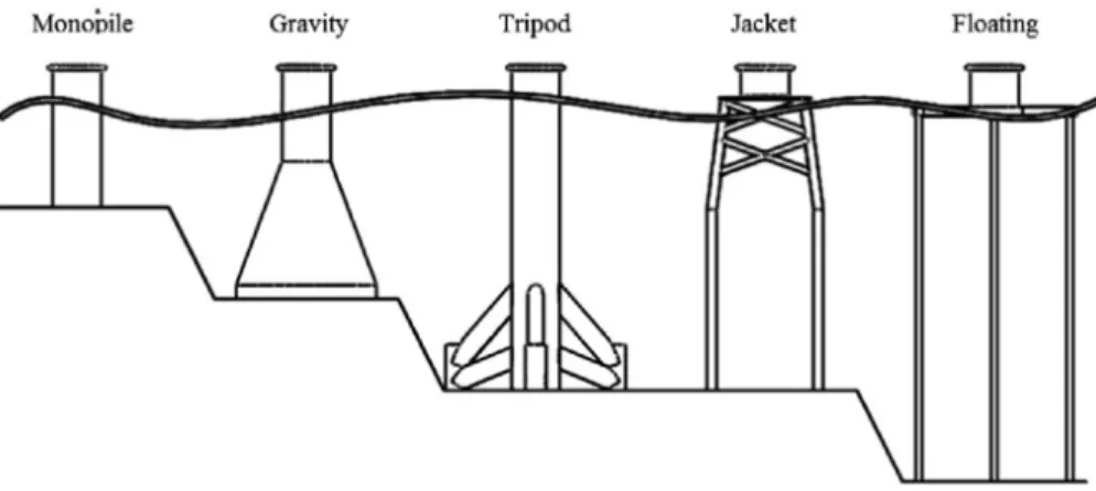
10 Offshore Substructures 35
10.1 Description . . . 35
10.1.1 Monopile Substructures . . . 37
10.1.2 Tripod Substructures . . . 37
10.1.3 Tripile Substructures . . . 38
10.1.4 Jacket Substructures . . . 38
10.1.5 Gravity substructures . . . 38
10.1.6 Floating Substructures . . . 39
10.2 Technical feasibilities . . . 39
10.3 Stages of Development . . . 40
10.4 Cost and Lifetime . . . 41
11 Protection Equipment 42 11.1 AC Circuit Breaker . . . 42
11.1.1 Description . . . 42
11.1.2 Technical feasibilities . . . 42
11.1.3 Stages of Development . . . 43
11.1.4 Cost and Lifetime . . . 43
11.2 DC Circuit Breaker . . . 43
11.2.1 Description . . . 43
11.2.2 Technical feasibilities . . . 44
11.2.3 Stages of Development . . . 44
11.2.4 Cost and Lifetime . . . 45
11.3 Fault Current Limiter . . . 45
11.3.1 Description . . . 45
11.3.2 Technical feasibilities . . . 45
11.3.3 Stages of Development . . . 46
11.3.4 Cost and Lifetime . . . 46
12 Auxiliary Equipment 47 12.1 Tapping equipment . . . 47
12.1.1 Description . . . 47
12.1.2 Technical feasibilities . . . 47
12.1.3 Stages of Development . . . 47
12.1.4 Cost and Lifetime . . . 47
12.2 Supervisory, control and data acquisition (SCADA) . . . 47
12.2.1 Description . . . 47
12.2.2 Technical feasibilities . . . 48
12.2.3 Stages of Development . . . 48
12.2.4 Cost and Lifetime . . . 48
13 Summary 49
Appendices 52
Appendix A HVDC Converter Station Configuration 52
Glossary
AC Alternating Current. 1, 2
CSC Current Source Converter. 2, 14 DC Direct Current. 2
DFIG Doubly-fed induction generator. 4 DRU diode rectifier unit. 17
FRC Fully Rated Converter. 4
HTS High Temperature Superconducting. 6, 8, 9 HVAC High Voltage Alternating Current. 1, 2, 6, 7, 10 HVDC High Voltage Direct Current. 1, 2, 10, 13, 14 LCC Line Commutated Converter. 12, 14–16 MI Mass Impregnated. 10
MV Medium Voltage. 1
MVAC Medium Voltage Alternating Current. 7 OHL Overhead Line. 2
OWPP Offshore Wind Power Plant. 1, 3, 14, 23 PMSG permanent magnet synchronous generator. 4 TCSC Thyristor Controlled Series Compensation. 28 TRL Technology Readiness Level. 3
VSC Voltage Source Converter. 2, 12, 14–16 WPP Wind Power Plant. 7, 8
WRIG wound rotor induction generator. 4 WRSG Wound rotor synchronous generator. 4 WT Wind Turbine. 1
XLPE Cross-linked polyethylene. 6, 7, 10
1 Introduction
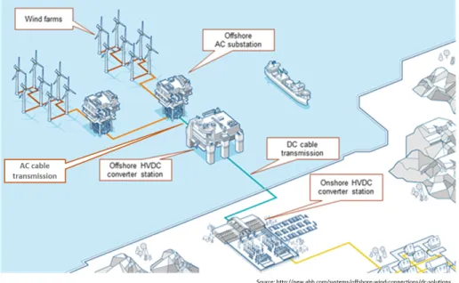
Traditionally, Offshore Wind Power Plants (OWPPs) are connected through many com- ponents as shown in the figure 1. An OWPP consists of controllable, variable speed
Figure 1: Traditional connection of offshore wind power plants
Wind Turbines (WTs). These WTs are connected through Medium Voltage (MV) sub- marine cables typically at voltage level of upto 33-66 kV to the Offshore Alterna- ting Current (AC) substation. The transformer in offshore AC substation steps up the voltage to 132-200 kV for further transmission. The stepping up of voltage is impor- tant to reduce the current flow through the cables. Reduced current flow decreases the copper/aluminium requirement for the cables as well reduce the power losses through them.
Offshore AC substation can be connected to the grid at shore either directly through High Voltage Alternating Current (HVAC) cables or through High Voltage Direct Cur- rent (HVDC) converters and HVDC cables.
HVDC transmission technology has been developed and applied from as early as 1880s. In the early 1950s, HVDC transmission technology was used for the deve- lopment of subsea interconnection with mercury arc valves used for electric AC/DC converters. HVDC transmission lines are applied when there is a need to transport high electrical power over long distances and/or in a controlled manner.
In terms of submarine applications, HVDC transmission technology is mainly ap- plied either for connecting offshore platforms and OWPPs to land or for transmitting electricity over long distances through the sea where overhead lines cannot be used.
Another subsea application can be for connecting the island networks to the main- land. HVDC transmission is the most viable solution available for the transfer of high
power across long subsea distances. However, choice between HVAC and HVDC is based on economic considerations. Furthermore, HVDC is a proven technology for transmission projects that interconnect asynchronous networks.1HVDC subsea trans- mission technology also has been largely applied in single point-to-point connections.
The system approach gives the effective rating. Current maximum HVDC power un- der planning is up to±600 kV and 2200 MW per bipole as a system.2Looking into the future, meshed HVDC subsea systems may become available. However, develop- ment of meshed HVDC networks today is still limited as circuit breaker technology for DC grid is still not commercially matured. Circuit breakers, so called switchgear, secure the operation of the meshed HVDC system. As per the Europacable report,3the development of this circuit breaker technology is in final development phase.
Vaféas et. al.4studied and enumerated the benefits of HVDC technology over con- ventional HVAC in the REALISEGRID project. HVDC technology has been proved to be attractive for various applications such as long distance power transmission, long submarine cable links and interconnection of asynchronous systems. There are mainly two types of HVDC technology. The more recent technology is self-commutated Voltage Source Converter (VSC) technology. VSC technology is more flexible than the more conventional line-commutated Current Source Converter (CSC) since it al- lows controlling active and reactive power independently.5 Independent power flow controllability along with the advantage of increased transmission capacity can make HVDC technology preferable to conventional HVAC. Although the choice of HVDC vs. HVAC should be made based on economic studies; since the investment cost of a VSC-HVDC converter station is generally higher than HVAC substation. However, the overall investment costs of a Direct Current (DC) transmission link can be lower than those ones of a corresponding AC interconnection if a certain transmission dis- tance is reached called “break-even” distance.6The break-even distance upon which DC is more economical is project dependent (typically between 80 and 120 km for offshore submarine cable connections, while for onshore applications, the break-even distance between an AC and DC Overhead Line (OHL) is in the order of magnitude of 700 km)7and the decision of using AC or DC should result from a techno-economic
1. Europacable,An Introduction to High Voltage Direct Current (HVDC) Underground Cables,http : //www.europacable.eu/wp-content/uploads/2017/07/Introduction_to_HVDC_Underground_
Cables_October_2011.pdf, 2011.
2. Europacable,An Introduction to High Voltage Direct Current (HVDC) Subsea Cables Systems,http:
/ / www . europacable . eu / wp - content / uploads / 2017 / 07 / Introduction - to - HVDC - Subsea - Cables-16-July-2012.pdf, 2012.
3. Ibid.
4. A Vaféas, S Galant, and T Pagano, “Final WP1 report on cost/benefit analysis of innovative technolo- gies and grid technologies roadmap report validated by the external partners,”REALISEGRID Deliverable D 1 (2011).
5. Gianluigi Migliavacca,Advanced technologies for future transmission grids(Springer Science & Bu- siness Media, 2012).
6. Ibid.
7. A Vaféas, S Galant, and T Pagano, “Final WP1 report on cost/benefit analysis of innovative technolo- gies and grid technologies roadmap report validated by the external partners,”REALISEGRID Deliverable D 1 (2011).
analysis including the line, station and losses components of costs.8, 9
1.1 Motivation
Building an offshore grid is a technically complex endeavour implying a significant number of components. While for AC connections the technology is mature and well known, in the area of power electronics and HVDC technology the component deve- lopment is in its more incipient phases. This has prompted for the creation of a techno- logy catalogue covering all the main components needed when developing offshore wind power and grids projects.
The main purpose of this Technology Catalogue is to serve as a common source for the techno-economic assessments done in the Baltic InteGrid project. To qualify for this, it should include both technical characteristics and cost parameters for all the relevant components of an OWPP and its connection to the grid.
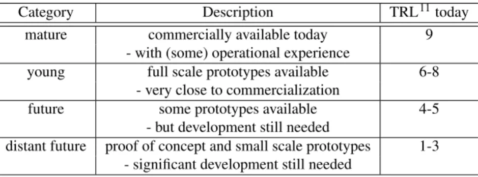
The technology development has been classified in four main categories in this technology catalogue and described in Table 1. European definition of Technology Readiness Level (TRL)10is associated with the categories.
Table 1: Categories of technology development
Category Description TRL11today
mature commercially available today 9
- with (some) operational experience
young full scale prototypes available 6-8
- very close to commercialization
future some prototypes available 4-5
- but development still needed
distant future proof of concept and small scale prototypes 1-3 - significant development still needed
1.2 Outline of the Report
This report aims to cover most of the technical components for offshore network star- ting from wind turbines up to the onshore connecting substation. This report contains small description of each of the components followed by stages of development, cost and lifetime.
8. Patrick PANCIATICI et al., “e-HIGHWAY 2050 Modular Development Plan of the Pan-European Transmission System 2050.”
9. Gianluigi Migliavacca,Advanced technologies for future transmission grids(Springer Science & Bu- siness Media, 2012).
10. European Commission,Technology readiness levels (TRL),https://ec.europa.eu/research/
participants/data/ref/h2020/wp/2014_2015/annexes/h2020-wp1415-annex-g-trl_en.pdf.
2 Wind Turbines
2.1 Description
Wind turbine technology has been drastically improving and has become matured du- ring the last decade. While wind turbine design objectives were traditionally convention- driven but they have been changed over these years to being optimized driven within the operating regime and market environment.12Not only the wind turbines have become larger in size, but also the wind turbine technology have progressed from fixed-speed, stall-controlled and with drive trains with gearboxes, to become pitch controlled, vari- able speed and with or without gearboxes.13Decreasing cost of power electronics also increasingly supports the trend toward variable speed turbines.
Offshore wind turbines are categorically converter based variable speed wind tur- bines.14
The most commonly applied variable speed wind turbines can be categorized into two types:
2.1.1 Doubly-fed Induction Generator (DFIG) based Wind Turbine
Doubly-fed induction generator (DFIG) configuration represents variable speed con- trolled wind turbine with a wound rotor induction generator (WRIG) and partial-scale frequency converters (rated to approx. 30% of nominal generator power) on the rotor circuit. Stator of the wind turbine generator is directly connected to the grid. Partial- scale frequency converter controls rotor speed. The speed range of the rotor is dicta- ted by power rating of the partial-scale frequency converter. Speed range is typically around pm30% of the synchronous speed. The frequency converters can provide ad- ditional support like reactive power compensation.15
2.1.2 FRC based Wind Turbine
In this configuration, full variable speed control of the wind turbine is achieved through full-scale frequency converters. The generator is isolated from the grid through this full-scale frequency converter. The frequency converter provides additional supports like reactive power compensation and a smooth grid connection. FRC based wind tur- bine can operate in the entire speed range as opposed to limited speed range of DFIG.
The generator can either be electrically excited (Wound rotor synchronous generator (WRSG)) or permanent magnet excited type (permanent magnet synchronous genera- tor (PMSG)).16Some FRC based wind turbines may have no gearbox but a bulky direct
12. Anca Daniela Hansen et al., “Grid integration impacts on wind turbine design and development,” in PowerTech, 2009 IEEE Bucharest(IEEE, 2009), 1–7.
13. Anca D Hansen et al., “Review of contemporary wind turbine concepts and their market penetration,”
Wind Engineering28, no. 3 (2004): 247–263.
14. Ibid.
15. Ibid.
16. Anca D Hansen et al.,Dynamic wind turbine models in power system simulation tool DIgSILENT, technical report (2004).
driven multipole generator.17
2.2 Technical feasibilities
Installed offshore wind turbines are typically today in the 2-6 MW range, which is a mature and well proven technology today. According to Wind Europe,18the average size of installed offshore wind turbine was 4.2 MW in 2015, a 13% increase over 2014.
This was due to the increased deployment of 4-6 MW turbines in 2015.19 However, all the major wind turbine suppliers are commercially offering wind turbines in the 6-8 MW range20, 21 with some of them being able to produce up to 9 MW,22 qualifying them as a young technology today, but with clear prospects and development timeline.
In the 10-20 MW range, there are no commercially available wind turbines today.
However, research efforts in providing initial designs are being performed, mainly by academia. A 10 MW reference wind turbine design has been developed by Technical University of Denmark (DTU).23In the European project-INNWIND, this design was up-scaled to 20 MW,24 however no detailed design data are available yet. This is considered a future technology.
2.3 Stages of Development
Mature
2.4 Cost and Lifetime
• Capex: 1500-2500 US$/kW25
• Opex: N/A
17. Anca D Hansen et al., “Review of contemporary wind turbine concepts and their market penetration,”
Wind Engineering28, no. 3 (2004): 247–263.
18. EWEA,The European offshore wind industry - key trends and statistics 2015, 2016,https://www.
ewea.org/fileadmin/files/library/publications/statistics/EWEA- European- Offshore- Statistics-2015.pdf.
19. Ibid.
20. Siemens Wind Power,SWT-7.0-154,http://www.siemens.com/global/en/home/markets/
wind/turbines/swt-7-0-154.html.
21. Mitsubishi Vestas Offshore,V164-8.0 MW,http://www.mhivestasoffshore.com/innovations /.
22. Mitsubishi Vestas Offshore,World’s most powerful wind turbine once again smashes 24 hour power generation record as 9 MW wind turbine is launched,http://www.mhivestasoffshore.com/new-24- hour-record/.
23. Bak, Christian and Zahle, Frederik and Bitsche, Robert and Kim, Taeseong and Yde, Anders and Henriksen, Lars Christian and Hansen, Morten Hartvig and Blasques, Jose Pedro Albergaria Amaral and Gaunaa, Mac and Natarajan, Anand,The DTU 10-MW Reference Wind Turbine,http://orbit.dtu.dk/
files/55645274/The_DTU_10MW_Reference_Turbine_Christian_Bak.pdf, 2013.
24.Innovative Wind Conversion Systems (10-20MW) for Offshore Applications, INNWIND Project,www.
innwind.eu.
25. Bak, Christian and Zahle, Frederik and Bitsche, Robert and Kim, Taeseong and Yde, Anders and Henriksen, Lars Christian and Hansen, Morten Hartvig and Blasques, Jose Pedro Albergaria Amaral and Gaunaa, Mac and Natarajan, Anand,The DTU 10-MW Reference Wind Turbine,http://orbit.dtu.dk/
files/55645274/The_DTU_10MW_Reference_Turbine_Christian_Bak.pdf, 2013.
• lifetime: 20-25 years
3 AC Cables
Most prevalent types of HVAC Cables are Cross-linked polyethylene (XLPE) cables.
Another technology, High Temperature Superconducting (HTS) cables is mature but their large application in electricity highways can be limited due to constraints of the cryogenic systems. However, HTS cables can be deployed in specific projects based on economic studies.
3.1 XLPE cables
XLPE cables belong to the class of extruded cables. Extruded cables can generally be categorized into 3 categories:
• EPR - ethylene propylene rubber
• PE - polyethylene
• XLPE - cross-linked polyethylene
Cross-linked polyethylene has good electrical properties such as low dielectric loss factor, which makes it feasible to operate at higher voltage than other kind of material like Poly Vinyl Chloride (PVC) insulated cables. Polyethylene as thermoplastic mate- rial is used as cable insulation but with applications limited by thermal constraints.26 Cross-linking is performed in XLPE through the process known as ‘vulcanization’ or
‘curing’. Chemical additives are added to the polymer in small quantity which enable the molecular chains of the polymer to be cross-linked into a lattice structure.27
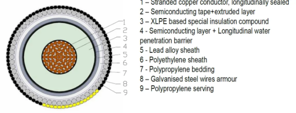
Figure 2: Example of XLPE cable design28
Example of XLPE cable design is shown in Figure 2. Extruded insulation cables consist of many layers. Surrounding the conductors, there is inner semi-conducting
26. Eric Alwyn Reeves and Martin Heathcote,Newnes electrical pocket book(Routledge, 2013).
27. Ibid.
28. Europacable,An Introduction to High Voltage Direct Current (HVDC) Subsea Cables Systems,http:
/ / www . europacable . eu / wp - content / uploads / 2017 / 07 / Introduction - to - HVDC - Subsea - Cables-16-July-2012.pdf, 2012.
screen layer, the insulation compound and an outer semi-conducting insulation screen, extruded simultaneously.29A semi-conducting water swelling tape separates the outer semi-conducting screen and the metallic sheath limiting water propagation along the cable core in case of cable damage. A layer of polyethylene compound is extruded over the lead alloy based metallic sheath.30
XLPE cables are used for both HVAC as well as Medium Voltage Alternating Cur- rent (MVAC).
3.1.1 Technical feasibilities
• Length: 20-100 km; However, maximum length depends on voltage rating and amount of shunt compensation .31
• Maximum Voltage: 500 kV32
• Current Rating: 1.9-2.6 kA33
• Cross-section: Example for Prysmian MVAC/HVAC cables is given in Table below.34
Rated Voltage (kV) Cross-section (mm2)
66 240-2000
110 400-2500
132 400-2500
150 400-2500
220 630-2500
275 630-2500
345 800-2500
400 800-2500
500 1600-2500
• Deep Sea Installation: 400kV subsea cables can be either single core or 3-core.
Although, sea depth does not influence maximum transmissible power through the cable, however, cable laying facilities can limit the cable diameter at the deepest water.35
29. Soo-Bong Lee et al., “Development of 250kV HVDC XLPE cable system in Korea,” inElectrical Insulating Materials (ISEIM), Proceedings of 2014 International Symposium on(IEEE, 2014), 334–337.
30. Europacable,An Introduction to High Voltage Direct Current (HVDC) Subsea Cables Systems,http:
/ / www . europacable . eu / wp - content / uploads / 2017 / 07 / Introduction - to - HVDC - Subsea - Cables-16-July-2012.pdf, 2012.
31. Grid Innovation Online,Technology Database,http : / / www . gridinnovation - on - line . eu / Technology-Database.
32. Prysmian,High Voltage Cables,http : / / nl . prysmiangroup . com / nl / business _ markets / markets/hv-and-submarine/downloads/datasheets/Prysmian-Delft-HVac.pdf.
33. Ibid.
34. Ibid.
35. Grid Innovation Online,Technology Database,http : / / www . gridinnovation - on - line . eu / Technology-Database.
3.1.2 Stages of Development
Mature
3.1.3 Cost and Lifetime
• Capex: 3675-4062 ke/km (installation cost = 29%)36
• Opex: 7.3-8.1 ke/km (OPEX assumed at a 0.2% p.a.)37
• Lifetime: N/A
The prices stated for the cables above also include installation costs that vary substanti- ally depending on the area of application. For example, the prices for the XLPE-HVAC cables can be higher than that for the XLPE-HVDC cables. The reason is that the in- stallation costs are included per km. The AC cables are mainly used for the array cabling of the Wind Power Plant (WPP), that means there are a lot of cables with a length of less than 1km. However, every cable needs lifting work and a connection on both ends. Therefore, extrapolating this cost toe/kmcan make the installation costs very high. Approximate CAPEX based on cable area of cross-section are as follows:
• 95mm2: 113ke/km
• 150mm2: 136ke/km
• 240mm2: 174ke/km
• 400mm2: 240ke/km
• 630mm2: 336ke/km
Installation costs are depending on the length and amount of lines of the WPP
3.2 HTS cables
The property of HTS to transmit power without resistance loss allows the utilities to increase power density by 2 to 8 times.38
Benefits of HTS Power Cables39
• Increased current carrying capability
• No resistive electrical losses
• Use of liquid nitrogen as coolant which in environmentally benign
• Can be installed into existing conduit infrastructure
36. Grid Innovation Online,Technology Database,http : / / www . gridinnovation - on - line . eu / Technology-Database.
37. Ibid.
38. SuperPower-Inc,HTS Transmission Cable,http://www.superpower- inc.com/content/hts- transmission-cable.
39. Ibid.
• Takes up less space than conventional cables therefore further expansion possible
• Increased power requirements of existing substations can be satisfied
• Can operate at high current levels with much lower losses also requiring less voltage transformations (reduced cost of transformers)
3.2.1 Technical feasibilities
• Length: 3 km; Although, there is no theoretical limitation in length however, actual maximum single length without joint installed is about 600 m. Major economic limitation for mass application of HTS lies mainly in the operation and maintenance of the cryogenic system.40
• Maximum Voltage: 220 kV41
• Current Rating: 4 kA42 3.2.2 Stages of Development
Mature 3.2.3 Cost
• Capex: N/A
• Opex: N/A
• Lifetime: N/A
Cost in future will depend on the evolution of the market and material properties of HTS in future.
40. Grid Innovation Online,Technology Database,http : / / www . gridinnovation - on - line . eu / Technology-Database.
41. Ibid.
42. Ibid.
4 HVDC Cables
4.1 Description
HVDC transmission technology is mainly applied when either transport of high electri- cal power over long distances becomes uneconomical for HVAC transmission; power transmission needs to be done with higher controllability and/or to connect two asyn- chronous networks.
Subsea application of HVDC transmission is predominantly used for connecting offshore wind farms to land or transmitting electricity over long distance through the sea where application of overhead lines may be technically or economically not fe- asible. However, HVDC cables are beginning to be used also for land transmission projects for transmitting high volume of power. HVDC is a proven technology for transmission projects that interconnect asynchronous networks.43
HVDC underground cables are used to carry medium and high power (100 MW
−1,000 MW) over distances above 50 km. HVDC underground cables have been commercially been used since the 1950s. Two types of HVDC cable technologies are mainly available commercially - Mass Impregnated (MI) Cables and XLPE Cables.
Self-contained fluid filled cables are also becoming popular however they are used for very high voltage and short connections due to hydraulic limitations.44
4.1.1 Self-Contained Fluid Filled Cables
Self-Contained Fluid Filled Cables are paper insulated oil filled cables. These kinds of cables are more suitable for HVDC transmission for short distances up to approx- imately 50 km. The insulation system in these cables need to be constantly under oil pressure. This oil pressure prevents from formation of cavities when oil contracts as the cable cools down. These kind of cables can be used for both AC and DC operations.
Examples using low pressure oil filled cables are the interconnections between Saudi Arabia - Egypt (“Aqaba Project”) and the Spain-Morocco project.45
4.1.2 Mass Impregnated Cables
Mass-impregnated subsea HVDC cables do not need oil feeding and therefore, there is no limitation in terms of length. Mass-impregnated cables are composed of a high viscous impregnating material which does not cause any leakage in events of cable da- mage/failure. Compared to oil filled cables, the compact design of Mass-impregnated subsea HVDC cables also allows for deep water applications. An example using mass- impregnated subsea HVDC cables is the interconnection between Spain - Mallorca
43. Europacable,An Introduction to High Voltage Direct Current (HVDC) Underground Cables,http : //www.europacable.eu/wp-content/uploads/2017/07/Introduction_to_HVDC_Underground_
Cables_October_2011.pdf, 2011.
44. Europacable,An Introduction to High Voltage Direct Current (HVDC) Subsea Cables Systems,http:
/ / www . europacable . eu / wp - content / uploads / 2017 / 07 / Introduction - to - HVDC - Subsea - Cables-16-July-2012.pdf, 2012.
45. Ibid.
(“Cometa Project”).46
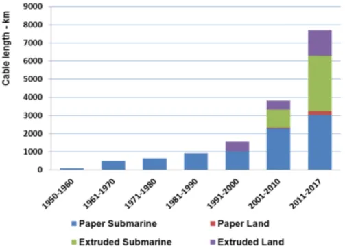
This type of cable is currently one of the most used, however, extruded cables are being used more and more in recent years as can be seen from Figure 3.47, 48
Figure 3: Evolution of length for mass impregnated paper cables and extruded cables for submarine and underground applications49
Mass impregnated cables has been in service for many years and is a matured technology that can be used for voltages up to±500 kV and 1600 A DC which corre- sponds to a maximum pole rating of 800 MW and bipole rating of 1600 MW. Conduc- tor sizes are typically up to 2500mm2(at transmission capacity of 2000 MW bipole).
46. Europacable,An Introduction to High Voltage Direct Current (HVDC) Subsea Cables Systems,http:
/ / www . europacable . eu / wp - content / uploads / 2017 / 07 / Introduction - to - HVDC - Subsea - Cables-16-July-2012.pdf, 2012.
47. E. Zaccone,High voltage underground and subsea cable technology options for future transmission in Europe, presentation at E-Highway2050 WP3 workshop April 15th, 2014 Brussels, 2014,http://www.e- highway2050 . eu / fileadmin / documents / Workshop4 / 7b _ Europacable _ for _ WP3 _ Workshop _ Technology_Presentation_15_April_2014_c.pdf.
48. Mircea Ardelean and Philip Minnebo,HVDC Submarine Power Cables in the World, JRC Technical Reports, 2015,http://publications.jrc.ec.europa.eu/repository/bitstream/JRC97720/
ld-na-27527-en-n.pdf.
49. E. Zaccone,High voltage underground and subsea cable technology options for future transmission in Europe, presentation at E-Highway2050 WP3 workshop April 15th, 2014 Brussels, 2014,http://www.e- highway2050 . eu / fileadmin / documents / Workshop4 / 7b _ Europacable _ for _ WP3 _ Workshop _ Technology_Presentation_15_April_2014_c.pdf.
Further improvement in voltage and capacity can be expected in the near future.50 4.1.3 Cross-Linked Poly-Ethylene Cables
Polymeric cables are only used in Voltage Source Converters(VSC) applications that al- low reversing power flow without reversing the polarity.51This technology has mainly been applied at voltages up to±200 kV (in service with a power capacity of 400 MW).
However, recent project such as European TEN-E France - Spain Interconnector (IN- ELFE) has voltage rating of±320 kV and power rating of 1000 MW per cable.52, 53
4.2 Technical feasibilities
• HVDC cables: XLPE
– Transmission Distance:>1000 km54
– Losses: 27 W/m (21 W/m in future) (Typical losses per circuit (bipole))55 – Maximum Voltage: 400-525-640 kV56 57
Recently 640 kV extruded HVDC cable system has been developed, howe- ver, mainly for underground applications.58
– Current rating: 1900 kA59
– Max Power per VSC substation (bipole): 1524-1710 MW (1710-1895 MW in future)60
– Max Power per LCC substation (bipole): 600 MW61
50. Europacable,An Introduction to High Voltage Direct Current (HVDC) Subsea Cables Systems,http:
/ / www . europacable . eu / wp - content / uploads / 2017 / 07 / Introduction - to - HVDC - Subsea - Cables-16-July-2012.pdf, 2012.
51. Europacable,An Introduction to High Voltage Direct Current (HVDC) Underground Cables,http : //www.europacable.eu/wp-content/uploads/2017/07/Introduction_to_HVDC_Underground_
Cables_October_2011.pdf, 2011.
52. Europacable,An Introduction to High Voltage Direct Current (HVDC) Subsea Cables Systems,http:
/ / www . europacable . eu / wp - content / uploads / 2017 / 07 / Introduction - to - HVDC - Subsea - Cables-16-July-2012.pdf, 2012.
53. P Labra Francos et al., “INELFE—Europe’s first integrated onshore HVDC interconnection,” inPower and Energy Society General Meeting, 2012 IEEE(IEEE, 2012), 1–8.
54. Grid Innovation Online,Technology Database,http : / / www . gridinnovation - on - line . eu / Technology-Database.
55. Ibid.
56. Ibid.
57. ABB,The new 525 kV extruded HVDC cable system, 2014,https://library.e.abb.com/public /7caadd110d270de5c1257d3b002ff3ee/The%5C%20new%5C%20525%5C%20kV%5C%20extruded%5C%
20HVDC%5C%20cable%5C%20system%5C%20White%5C%20PaperFINAL.pdf.
58. NKT,640 kV extruded HVDC cable system, 2017,http : / / www . nkt . de / fileadmin / user _ upload / 01 _ Page _ images _ global / general _ images _ pages / About _ us / Innovation / 640 _ kV _ extruded_HVDC.pdf.
59. Grid Innovation Online,Technology Database,http : / / www . gridinnovation - on - line . eu / Technology-Database.
60. Ibid.
61. Ibid.
– Cross-section Area: 2500mm2for voltage rating of 320 kV62 – Deep sea installations: 500 m (1000 m in future)63
• HVDC cables: MI – Losses: 10.4 W/m64
– Maximum Voltage: 600 kV65
– Current rating: 1555 kA (1950 kA in future)66 – Max Power per VSC substation (bipole): 1860 MW67
– Max Power per Line Commutated Converter (LCC) substation (bipole):
1860 MW68
– Cross-section Area: 2000mm2for 300 kV69 – Deep sea installations: 1600 m (2000 m in future)70
Europe’s longest interconnector: NordLink project with VSC converters rated at +/- 525 kV and 1400 MW bipole configuration having route length of 623 km route length is being built71
4.3 Stages of Development
Mature
4.4 Cost and Lifetime
• HVDC cables: XLPE
– Capex: 1470-1625 ke/ km (Installation costs: 29%)72 – Opex: 2.9-3.2 ke/km (OPEX assumed at a 0.2% p.a.)73
62. ENTSO-E,Offshore Transmission Technology,http://www.benelux.int/files/6814/0923/
4514/offshore_grid_technology.pdf.
63. Grid Innovation Online,Technology Database,http : / / www . gridinnovation - on - line . eu / Technology-Database.
64. Ibid.
65. Ibid.
66. Ibid.
67. Ibid.
68. Ibid.
69. Northern Pass Project-Diagrams of Cross-Section of Underground Cables,https : / / energy . go v / sites / prod / files / 2013 / 08 / f2 / Exhibit \ %203 \ %20 - \ % 20Diagrams \ %20of \ %20Cross - Section\%20of\%20Underground\%20Cables.pdf.
70. Grid Innovation Online,Technology Database.
71. Magnus Callavik, Peter Lundberg, and O Hansson, “NORDLINK Pioneering VSC-HVDC intercon- nector between Norway and Germany,”ABB White Paper, 2015,
72. Grid Innovation Online,Technology Database,http : / / www . gridinnovation - on - line . eu / Technology-Database.
73. Ibid.
– lifespan:>40 years74
• HVDC cables: MI – Capex: N/A – Opex: N/A
– lifespan:>40 years75
• HVDC cables: Self-Contained Fluid Filled – Capex: N/A
– Opex: N/A – lifespan: N/A
Experience of HVDC underground cabling and their cost is currently limited. Ba- sed on analysis conducted by Realise Grid76in 2010, the cost of HVDC underground cables (two cables, ±350 kV, 1,100 MW) is between 1 - 2.5 millione/km. Some estimations of costs for HVDC cables for different cross-sections can be found in some reports.77, 78, 79
74. Grid Innovation Online,Technology Database,http : / / www . gridinnovation - on - line . eu / Technology-Database.
75. Ibid.
76.EU-FP7 project - REseArch, methodoLogies and technologieS for the effective development of pan- European key GRID infrastructures to support the achievement of a reliable, competitive and sustainable electrical supply,http://realisegrid.rse-web.it/.
77. Kalid Yunus, “Steady state analysis of HVDC grid with Wind Power Plants” (PhD diss., Chalmers University of Technology, 2017).
78. ENTSO-E,Offshore Transmission Technology,http://www.benelux.int/files/6814/0923/
4514/offshore_grid_technology.pdf.
79. REALISEGRID,D3.3.2 Review of costs of transmission infrastructures, including cross border con- nections,http://realisegrid.rse- web.it/content/files/File/Publications%5C%20and%
5C%20results/Deliverable_REALISEGRID_3.3.2.pdf.
5 AC-DC Converters
All the electricity transmission and distribution networks in the world are based on AC systems. In order to transmit power from far off OWPP through HVDC cables, AC power are converted to DC power and vice versa using AC-DC power converters.
Power converters currently available on the market can be classified in two major cate- gories in terms of technology: Line Commutated Converters(LCC) and Voltage Source Converter (VSC).80 Both of these type of technologies can be used in a full HVDC scheme (AC/DC converter - HVDC line or cable - DC/AC converter) or in a back-to- back (B2B) HVDC scheme (AC/DC converter - DC circuit - DC/AC converter, with all these components installed in a single station) or a more recent configuration for multi-terminal HVDC (MTDC) applications.81
LCC and VSC have different characteristics and are operated in different manner because of the intrinsic differences of power electronic components. The characteris- tics of LCC and VSC are compared in Table 2.
5.1 Line Commutated Converters
5.1.1 Description
LCC or CSC are the conventional, mature and well established power converter techno- logy which has been used to convert electrical current from AC to DC and vice versa since early 1950. Such converters require robust AC voltage source at either end.
Multi-terminal LCC connections are possible and exist (two schemes exist). Howe- ver, larger systems with a more complex structure may not be practical configuration mainly due to limitations on controllability of LCC converters.82
5.1.2 Technical feasibilities
• Voltage (line to ground) for converter: 800-1100 kV83
• Voltage (line to ground) for cables: 550 kV84
• Current: 4-5 kA (6 kA in future)85
• Max Power per substation (bipole) : 8-11 GW (upto 13.2 GW in future)86
80. Europacable,An Introduction to High Voltage Direct Current (HVDC) Subsea Cables Systems,http:
/ / www . europacable . eu / wp - content / uploads / 2017 / 07 / Introduction - to - HVDC - Subsea - Cables-16-July-2012.pdf, 2012.
81. e-Highway2050,Technology Assessment Report (HVDC) - Annex to D3.1 - Technology Assessment Report,http://www.e-highway2050.eu/fileadmin/documents/Results/D3/report_HVDC.pdf, 2014.
82. Ibid.
83. Grid Innovation Online,Technology Database,http : / / www . gridinnovation - on - line . eu / Technology-Database.
84. Ibid.
85. Ibid.
86. Grid Innovation Online,Technology Database,http : / / www . gridinnovation - on - line . eu / Technology-Database.
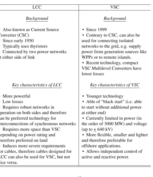
Table 2: Comparison between LCC and VSC
LCC VSC
Background Background
• Also known as Current Source • Since 1999
Converter (CSC) • Contrary to CSC, can also be
• Since early 1950 used for connecting isolated
• Typically uses thyristors networks to the grid, e.g. supply
• Connected by two power networks power from generation sources like at either side of link WPPs or to remote islands.
• Recent technology, compact VSC Multilevel Converters have lower losses
Key characteristics of LCC Key characteristics of VSC
• More powerful • Younger technology
• Low losses • Able of “black start” (i.e. able
• Requires robust networks in to start without additional power operation on both sides and therefore at either end)
can be preferred technology for • Currently limited in power (in interconnections of synchronous networks the order of 3000 MW) and voltage
• Requires more space than VSC (up to + 640 kV)
depending on power rating and • More flexible, smaller and lighter therefore preferred on land and therefore preferable for
• Induces more severe requirements offshore applications.
for cables, therefore cables designed for • Allows independent control of LCC can also be used for VSC, but not active and reactive power.
vice versa.
• Maximum length of the line: 2000 km87
• Maximum length of the cable: 580-600 km88
• Transmission Losses: 0.7-1.1% of rated power per converter station.89A conver- ter station usually contains converters, capacitors or synchronous condensers for reactive power, filters for harmonic suppression, switch gears, auxillary equip- ment and transformers.
87. Grid Innovation Online,Technology Database,http : / / www . gridinnovation - on - line . eu / Technology-Database.
88. Ibid.
89. Ibid.
5.1.3 Stages of Development
Mature
5.1.4 Cost and Lifetime
• Capex: 101-112 Me/GW (Installation costs: 37% )90
• Opex: 2% of investment costs per year91
• lifetime: 40 years92
Cost ranges are given per “per terminal" for the typical 1000 MW LCC configuration at 2013.93
5.2 Voltage Source Converters
5.2.1 Description
VSC are self-commutated converters using devices suitable for high power and high voltage applications. This technology can rapidly control both active and reactive po- wer independently.94It allows higher flexibility and controllability to place converters at different locations in the AC network since no robust AC voltage source is required to be connected at its end. Although there are some technology challenges that still needs to be addressed, such as DC breakers, higher powers, losses reduction etc. for larger deployment in multi-terminal applications.95
5.2.2 Technical feasibilities
• Voltage (line to ground) for converter: 500-800 kV (1100 kV in future)96
• Voltage (line to ground) for cables: 500 kV97
• Current: 1.5-3 kA (3-4 kA in future)98
• Max Power per substation (bipole) : 2000-4800 MW (6400 MW in future)99
90. Grid Innovation Online,Technology Database,http : / / www . gridinnovation - on - line . eu / Technology-Database.
91. Ibid.
92. Ibid.
93. Ibid.
94. J Duncan Glover, Mulukutla S Sarma, and Thomas Overbye,Power System Analysis & Design, SI Version(Cengage Learning, 2012).
95. e-Highway2050,Technology Assessment Report (HVDC) - Annex to D3.1 - Technology Assessment Report,http://www.e-highway2050.eu/fileadmin/documents/Results/D3/report_HVDC.pdf, 2014.
96. Grid Innovation Online,Technology Database,http : / / www . gridinnovation - on - line . eu / Technology-Database.
97. Ibid.
98. Ibid.
99. Ibid.
• Maximum length of the line: 700-2000 km (3000 km in future)100
• Maximum length of the cable: 400 km101(600-1000 km in future)102
760 km long HVDC interconnector called Viking Link between Denmark and UK is being proposed.103
• Transmission Losses: 0.9-1.3% of rated power (0.7-1.1% in future) per conver- ter station.104A converter station usually contains converters, capacitors or syn- chronous condensers for reactive power, filters for harmonic suppression, switch gears, auxillary equipment and transformers.
5.2.3 Stages of Development
Mature
5.2.4 Cost and Lifetime
• Capex: 106-118 ke/MW (Installation costs: 31%)105
• O&M costs: 2% of investment costs per year106
• Lifetime: 40 years107
Cost ranges are given per “per terminal" for typical configuation of a bipolar VSC terminal of power rating of 1100 MW at 2013.108Some estimations of costs for VSC for different power ratings can be found in some reports as well.109, 110, 111
5.3 Diode Rectifier Units
5.3.1 Description
The design of diode rectifier unit (DRU) developed from an idea originated at the Uni- versity of Valencia in Spain, replaces the air-insulated IGBT based traditional converter
100. Grid Innovation Online,Technology Database,http : / / www . gridinnovation - on - line . eu / Technology-Database.
101.NordBalt,https://en.wikipedia.org/wiki/NordBalt.
102. Grid Innovation Online,Technology Database,http : / / www . gridinnovation - on - line . eu / Technology-Database.
103.Viking Link,http://viking-link.com/.
104. Grid Innovation Online,Technology Database,http : / / www . gridinnovation - on - line . eu / Technology-Database.
105. Ibid.
106. Ibid.
107. Ibid.
108. Ibid.
109. Kalid Yunus, “Steady state analysis of HVDC grid with Wind Power Plants” (PhD diss., Chalmers University of Technology, 2017).
110. ENTSO-E,Offshore Transmission Technology,http://www.benelux.int/files/6814/0923/
4514/offshore_grid_technology.pdf.
111. REALISEGRID,D3.3.2 Review of costs of transmission infrastructures, including cross border con- nections,http://realisegrid.rse- web.it/content/files/File/Publications%5C%20and%
5C%20results/Deliverable_REALISEGRID_3.3.2.pdf.
and air-insulated DC switch gear — which requires much space and costly air conditi- oning with diode rectifiers.
For example, a 0.9GW VSC requires 50,000 cubic metres of space. Whereas, DRU with a 1.2GW rating requires three platforms each with a pair of DRUs converting from 66kV to 106.7kV strung together to add up to 320kV as provided by the VSCs used today. The three platforms have a total volume of just 6,500 cubic metres, or a nearly 90% volume saving on the VSC platform.112
DRU are simple, robust, encapsulated and have low losses & low maintenance costs. However, DRU does not allow bidirectional power flow as compared to VSC technology. Since WTs need auxiliary power to maintain systems, mainly grid outage;
therefore additional AC cable is needed running parallel to the DC cables from the onshore network.
AC voltage control is performed by the WTs 5.3.2 Technical feasibilities
• Nominal power: 200 MW113
• Nominal voltage AC: 66 kV114
• Nominal voltage DC: 106.7 kV115
• Size fits for transport by road and ship116
• Bio degradable and flame retardant ester insulation117 5.3.3 Stages of Development
Future
5.3.4 Cost and Lifetime
• Capex: N/A
• Opex: N/A
• lifetime: N/A
112. Sara Knight,Analysis: Siemens’ radical substation plan, News Article - WindPower Offshore, 2015, http://www.windpoweroffshore.com/article/1338456/analysis- siemens- radical- substa tion-plan.
113. Grid Innovation Online,Technology Database,http : / / www . gridinnovation - on - line . eu / Technology-Database.
114. Ibid.
115. Ibid.
116. Ibid.
117. Ibid.
6 DC-DC Converters
6.1 Description
This would be a device to convert one DC voltage to another DC voltage level and have equivalent function of a transformer in an AC grid. The AC transformer has greatly fa- cilitated AC transmission systems to operate at different voltage levels (110kV, 220kV, 400kV etc.) optimising the AC grid and its components. The DC equivalent can fulfil the same function in future HVDC grid also sometimes referred as Supergrid. Unless the Supergrid is specifically designed to operate at a common DC voltage, DC–DC converters will be essentially required to combine DC networks at different voltage levels.118, 119
There has been some recent standardisation efforts to unify voltage levels and to avoid the need for DC-DC conversion. However, still different voltage levels may ap- pear. For example, several different DC voltage levels are already applied for offshore wind integration in Germany. The fast progress in converter and cable technology also implies that significantly higher voltages can be foreseen in future. Utilising a standard voltage would waste future possible benefits from improved future voltage ratings.
There are generally two possibilities to connect two different DC voltage levels:
• With a DC-DC converter
• Through regular 50 Hz AC with an DC-AC converter and an AC-DC converter120 A DC-DC converter is likely to be cheaper and more efficient than two separate converters with regular 50Hz AC in between.121DC-DC converter also has the advan- tage to regulate the current or power flow through the converter, which helps to operate a meshed DC grid. It could even be applied for this purpose only, connecting two buses of the same voltage level. However, there is other component specialised for this kind of function called DC current flow controller.122 123
DC-DC converters topologies can be effectively classified into two groups:124
• Isolated DC-DC Converters
• Non-isolated DC-DC Converters
118. e-Highway2050,Technology Assessment Report (HVDC) - Annex to D3.1 - Technology Assessment Report,http://www.e-highway2050.eu/fileadmin/documents/Results/D3/report_HVDC.pdf, 2014.
119. Friends of the SuperGrid,Roadmap to the Supergrid Technologies,http://mainstream- downlo ads.opendebate.co.uk/downloads/WG2_Roadmap_to_the_Supergrid_Technologies_2013_
Final_v2.pdf, 2013.
120. Til Kristian Vrana and Raymundo E Torres Olguin, “Technology perspectives of the North Sea Offs- hore and storage Network (NSON),” 2015,
121. Ibid.
122. Ibid.
123. CD Barker and RS Whitehouse, “A current flow controller for use in HVDC grids,” in10th IET Inter- national Conference on AC and DC Power Transmission (ACDC 2012)(IET, 2012).
124. Til Kristian Vrana and Raymundo E Torres Olguin, “Technology perspectives of the North Sea Offs- hore and storage Network (NSON),” 2015,
6.1.1 Isolated DC-DC Converters
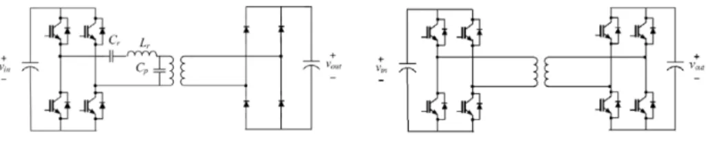
In an isolated DC-DC converter, the input and the output port are isolated using gal- vanic insulation. Isolated DC-DC converter comprises of two AC-DC converters con- nected to each other by a transformer. Example of possible topology is shown in Figure 4. Main design parameters of an isolated DC-DC converter are switching frequency and
Figure 4: Isolated DC-DC converters
left: Resonant bridge converter; right:Dual active bridge converter125
AC side frequency. AC side frequency is typically higher than the network nominal fre- quency (50/60 Hz). Operating in high frequency can allow for significant reduction of the size and volume of the transformers and components like capacitors and inductors.
However, a higher frequency leads to increased power losses and complex design of transformer (e.g. amorphous core materials, Litz wires).126, 127, 128
Availability of DC-DC converter for high power application as market product is rather limited and studied academically for power ratings spanning from tens of kVs to a few MWs and with an AC operating frequency in the kHz range using several topologies.129, 130, 131, 132, 133
125. Til Kristian Vrana and Raymundo E Torres Olguin, “Technology perspectives of the North Sea Offs- hore and storage Network (NSON),” 2015,
126. Robert L Steigerwald, Rik W De Doncker, and H Kheraluwala, “A comparison of high-power DC- DC soft-switched converter topologies,”IEEE transactions on industry applications32, no. 5 (1996): 1139–
1145.
127. Abdelrahman Hagar, “A new family of transformerless modular DC-DC converters for high power applications” (PhD diss., University of Toronto, 2011).
128. Til Kristian Vrana and Raymundo E Torres Olguin, “Technology perspectives of the North Sea Offs- hore and storage Network (NSON),” 2015,
129. J Taufiq, “Power electronics technologies for railway vehicles,” inPower Conversion Conference- Nagoya, 2007. PCC’07(IEEE, 2007), 1388–1393.
130. Liyu Yang et al., “Design and analysis of a 270kW five-level dc/dc converter for solid state transformer using 10kV SiC power devices,” inPower Electronics Specialists Conference, 2007. PESC 2007. IEEE (IEEE, 2007), 245–251.
131. Michael Steiner and Harry Reinold, “Medium frequency topology in railway applications,” inPower Electronics and Applications, 2007 European Conference on(IEEE, 2007), 1–10.
132. G Ortiz et al., “1 Megawatt, 20 kHz, isolated, bidirectional 12kV to 1.2 kV DC-DC converter for renewable energy applications,” inPower Electronics Conference (IPEC), 2010 International(IEEE, 2010), 3212–3219.
133. Stephan Meier et al., “Design considerations for medium-frequency power transformers in offshore wind farms,” inPower Electronics and Applications, 2009. EPE’09. 13th European Conference on(IEEE, 2009), 1–12.
6.1.2 Non-Isolated DC-DC Converters
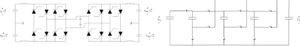
Non-isolated DC-DC converters are structurally simpler, cheaper and smaller than iso- lated converters.134, 135Two topologies are shown as an example in Figure 5. However, these converters are only capable of achieving a limited voltage ratio, which reduces the scope of application for these types of converters.
Figure 5: Non-isolated DC-DC converters136
left: Bidirectional high-power DC transformer137; right:Modular multi-level capacitor- clamped DC-DC converter138
Classical DC-DC converter configurations such as buck, boost, cuk are not suitable for high power applications since they require large duty cycles at higher conversion ratio which lead to low efficiency and reliability. There are some proposals in the litera- ture, for example a switched capacitor multilevel DC-DC converter has been proposed by Zhang et. al.139 and Vrana et. al.140 A main limitation lies in terms of lack of bidirectional power and modularity.141, 142Modular multilevel capacitor clamped con- verters are proposed by Vrana et. al.143 and Khan & Tolbert144Although modular multilevel capacitor clamped converter has advantage of modular design, bidirectio- nal and high frequency operation and low current ripple at input and output; but it has major drawback in terms of unequal voltage stress at the switches.145, 146 Anot-
134. Til Kristian Vrana and Raymundo E Torres Olguin, “Technology perspectives of the North Sea Offs- hore and storage Network (NSON),” 2015,
135. Abdelrahman Hagar, “A new family of transformerless modular DC-DC converters for high power applications” (PhD diss., University of Toronto, 2011).
136. Til Kristian Vrana and Raymundo E Torres Olguin, “Technology perspectives of the North Sea Offs- hore and storage Network (NSON),” 2015,
137. Dragan Jovcic, “Bidirectional, high-power DC transformer,”IEEE transactions on Power Delivery24, no. 4 (2009): 2276–2283.
138. Faisal H Khan and Leon M Tolbert, “A multilevel modular capacitor-clamped DC–DC converter,”
IEEE Transactions on Industry Applications43, no. 6 (2007): 1628–1638.
139. Fan Zhang et al., “A new design method for high-power high-efficiency switched-capacitor DC–DC converters,”IEEE Transactions on Power Electronics23, no. 2 (2008): 832–840.
140. Til Kristian Vrana and Raymundo E Torres Olguin, “Technology perspectives of the North Sea Offs- hore and storage Network (NSON),” 2015,
141. Abdelrahman Hagar, “A new family of transformerless modular DC-DC converters for high power applications” (PhD diss., University of Toronto, 2011).
142. Til Kristian Vrana and Raymundo E Torres Olguin, “Technology perspectives of the North Sea Offs- hore and storage Network (NSON),” 2015,
143. Ibid.
144. Faisal H Khan and Leon M Tolbert, “A multilevel modular capacitor-clamped DC–DC converter,”
IEEE Transactions on Industry Applications43, no. 6 (2007): 1628–1638.
145. Abdelrahman Hagar, “A new family of transformerless modular DC-DC converters for high power applications” (PhD diss., University of Toronto, 2011).
146. Til Kristian Vrana and Raymundo E Torres Olguin, “Technology perspectives of the North Sea Offs-
her interesting topology is soft-switched transformer-less topologies using thyristors.
However, expensive large resonant capacitor is needed for this kind of technology.147
6.2 Technical feasibilities
N/A
6.3 Stages of Development
Distant future
6.4 Cost and Lifetime
• Capex: N/A
• Opex: N/A
• lifetime: N/A
hore and storage Network (NSON),” 2015,
147. Til Kristian Vrana and Raymundo E Torres Olguin, “Technology perspectives of the North Sea Offs- hore and storage Network (NSON),” 2015,
7 Filters
Large OWPPs consist many non-linear devices such as power electronic devices in wind turbines, FACTS devices and/or HVDC transmission and other passive compo- nents such as cable arrays, transformers, transmission cables etc. Consequently, there are many harmonic generation sources.148Bradt et. al.149summarize the most impor- tant issues with respect to harmonics and resonances within wind power plants.
Primarily there are two ways to mitigate harmonics in WPPs: (i) avoiding harmo- nic resonance and emission by appropriate design (ii) use of harmonic filters. A good design can avoid high levels of harmonic voltages or currents through system layout, component selection and tuning of controller parameters. Both passive and active har- monic filtering can be used for harmonic mitigation. Passive filter technology is the state-of-the-art technology. Passive filter requires extensive system knowledge during the WPP design, which is very complex process since, there are many uncertainties involved in this process.
Although active and hybrid filters have been commonly used for harmonic filtering in many other industrial applications, however they have not been so common practice in WPP applications. Passive filters are more common for WT level and on the sy- stem level, e.g. point of common coupling (PCC). A major challenge for passive filter is that resonance can occur due to natural frequency matching with line impedance.
Active filters have recently being introduced more and more for WTs as well, with the development of semiconductor devices and improvement of current control strategies.
7.1 Passive Filter
7.1.1 Description
Passive filters consist of a bank of tuned LC filters and/or low-pass/high-pass filter.
They have been very popular owing to low initial cost and high efficiency. They have following disadvantages:150
• Filtering is strongly dependent on source impedance.
• Harmonic currents on the source side can drastically increase at certain frequen- cies owing to parallel resonance between source and passive filter.
• Similarly, excessive harmonic currents can flow into the passive filter due to series resonance with source impedance.151
148. Vladislav Akhmatov, Jørgen Nygaard Nielsen, Jan Thisted, et al., “Siemens Wind Power 3.6 MW wind turbines for large offshore wind farms,” inProc. 7th International Workshop on Large Scale Integration of Wind Power and on Transmission Networks for Offshore Wind Farms(Energynautics GmbH, 2008), 494–
497.
149. M Bradt et al., “Harmonics and resonance issues in wind power plants,” inTransmission and Distribu- tion Conference and Exposition (T&D), 2012 IEEE PES(IEEE, 2012), 1–8.
150. Hideaki Fujita and Hirofumi Akagi, “A practical approach to harmonic compensation in power systems-series connection of passive and active filters,”IEEE Transactions on industry applications27, no. 6 (1991): 1020–1025.
151. Hideaki Fujita and Hirofumi Akagi, “A practical approach to harmonic compensation in power