Research Collection
Doctoral Thesis
Investigations on Test-Mass Actuation and Rotation Measurement for Gravitational Wave Detectors
Author(s):
Meshksar, Neda Publication Date:
2021
Permanent Link:
https://doi.org/10.3929/ethz-b-000469094
Rights / License:
In Copyright - Non-Commercial Use Permitted
This page was generated automatically upon download from the ETH Zurich Research Collection. For more information please consult the Terms of use.
ETH Library
i
INVESTIGATIONS ON
T EST -M ASS A CTUATION AND
R OTATION M EASUREMENT FOR
G RAVITATIONAL W AVE D ETECTORS
N
EDAM
ESHKSARDiss.-No. ETH 27178 Eidgenössische Technische Hochschule Zürich
Diss.-No. ETH 27178
Investigations on Test-Mass Actuation and Rotation Measurement for
Gravitational Wave Detectors
A thesis submitted to attain the degree of DOCTOR OF SCIENCES OF ETH ZURICH
(DR. SC. ETH ZURICH)
by
NEDA MESHKSAR
M.Sc., Leibniz Universität Hannover
born on September 20th 1985 citizen of Iran
accepted on the recommendation of PROF. DR. DOMENICO GIARDINI
DR. LUIGI FERRAIOLI
PROF. DR. GERHARD HEINZEL
ASSOC. PROF. DR. WILLIAM J. WEBER
PROF. DR. PHILIPPE JETZER
Zurich, 2021
Supervisor: Prof. Dr. Domenico Giardini D-ERDW, ETH Zürich Co-Examiner: Dr. Luigi Ferraioli
D-ERDW, ETH Zürich Co-Examiner: Prof. Dr. Gerhard Heinzel
Albert Einstein Institute, Leibniz Universität Hannover External Examiner: Assoc. Prof. Dr. William J. Weber
Università di Trento External Examiner: Prof. Dr. Philippe Jetzer
Universität Zürich
Chairperson: Prof. Dr. Andreas Fichtner D-ERDW, ETH Zürich Date of Defence: December 11th2020
Dedicated to:
my mother, a strong woman and an inspiring example for me, my father, who always motivated me to grow in my academic path,
Saba, my wonderful sister and a real friend, Mandana, a generous mentor and a valuable friend.
vii
Abstract
Direct detection of gravitational waves by the on-ground detectors opened a new era in astronomy. These powerful messengers allow us to investigate a huge part of the universe, that does not interact with electromagnetic waves.
Although the on-ground detectors are the most precise instruments ever made, the noisy nature of the measurement environment, the Earth, limits the measurement bandwidth.
This limitation can be overcome by moving to space, far away from the Earth or other planets, to obtain a calm and large laboratory for our giant and ultra sensitive detectors.
This enables us to detect the gravitational waves of more fascinating sources and to understand our universe more than ever.
Currently, the European Space Agency (ESA) is leading theLaser Interferometer Space Antenna(LISA) mission. The first space-based gravitational wave detector, which is scheduled for the early 2030s. The sophisticated technology requirements for LISA have been already tested by theLISA Pathfindersatellite, which flew from December 2015 to July 2017 and obtained a performance better than expected.
In the LISA Pathfinder mission two test-masses were put in free-fall along the sensitive measurement axis. This was the axis connecting the centers of the test-masses. The relative displacement of the test-masses was then monitored precisely by a laser inter- ferometer, from which the main mission observable, namely the relative acceleration of the test-masses was calculated. The position of the test-masses in other degrees of freedom were controlled by electrostatic actuators in the Gravitational Reference Sensors.
Electrostatic actuation will be largely integrated into the LISA mission, and thus, it is crucial to investigate its precision and verify any optimization requirements for LISA.
This is especially due to the fact, that inaccuracies in the electrostatic actuation influence the mission observable directly.
Precise actuation is not possible without providing precise test-mass position readout.
The science interferometers on board LISA Pathfinder and LISA provide a high sensitive position readout along the main measurement axis. But the other degrees of freedom are sensed by capacitive sensors, which provide less sensitive measurements compared to the interferometric methods. Due to the complex setup and large scale of the typical interferometers it is not possible to apply them for sensing the other degrees of freedom.
However, many investigations are progressing to obtain small scaled, simple structured and high sensitive interferometers, that can ideally be applied in the future gravitational wave detectors and graviometers.
This thesis considers the open questions regarding the test-mass actuation and position sensing. In the first part, it investigates the accuracy of actuation electronics in the Gravitational Reference Sensors of the LISA Pathfinder and the LISA missions, and in
viii
the second part it proposes an interferometer setup for high precision and wide-range test-mass rotation measurements.
ix
Zusammenfassung
Der direkte Nachweis der Gravitationswellen durch die Detektoren auf der Erde eröffnete eine neue Ära in der Astronomie. Mit diesen mächtigen Botenstoffen können wir einen großen Teil des Universums untersuchen, der nicht mit elektromagnetischen Wellen interagiert.
Obwohl die Gravitationswellendetektoren auf der Erde die präzisesten Instrumente sind, die jemals hergestellt wurden, begrenzt die verrauschte Natur der Erde die Messbandbre- ite. Diese Einschränkung kann durch die Verlegung von Messungen in den Weltraum überwunden werden. Weit weg von der Erde und anderen Planeten ermöglicht die Rauscharmut die hochpräzise Messung. Dies würde es uns ermöglichen, die Gravitation- swellen von faszinierenderen Quellen zu messen und unser Universum mehr denn je zu verstehen.
Derzeit leitet die Europäische Weltraumorganisation (ESA) die MissionLaser Interferom- eter Space Antenna(LISA), der erste weltraumgestützte Gravitationswellendetektor, der Anfang der 2030er Jahre eingesetzt werden soll. Die hoch entwickelten Technologiean- forderungen für LISA wurden bereits vom SatellitenLISA Pathfindergetestet, der vom Dezember 2015 bis Juli 2017 flog und eine viel bessere Leistung erzielte als erwartet.
In der LISA Pathfinder-Mission wurden zwei Testmassen entlang der empfindlichen Mes- sachse in den freien Fall gebracht. Dieses war die Achse, die die Zentren der Testmassen verband. Die relative Verschiebung der Testmassen wurde dann mit einem Laserinterfer- ometer genau gemessen, aus dem die Missionsobservabel, die relative Beschleunigung der Testmassen, berechnet wurde. Die Position der Testmassen in anderen Freiheitsgraden wurde durch einen elektrostatischen Kontrollmechanismus gesteuert, der ein Teil der sogenannten Gravitationsreferenzsensoren ist. Dieser Mechanismus wird weitgehend in die LISA-Mission integriert. Daher ist es wichtig, seine Präzision zu untersuchen und etwaige Optimierungsanforderungen vor der Integration in LISA zu überprüfen. Dies liegt insbesondere daran, dass Ungenauigkeiten in der elektrostatischen Positionssteuerung die Missionsobservable direkt beeinflusst.
Die genaue Positionssteuerung der Testmasse ist ohne einer genauen Positionserfas- sung der Testmasse nicht möglich. Die Interferometer im LISA Pathfinder und LISA Sattelitten bieten eine hochempfindliche Positionsmessung entlang der empfindlichen Messachse. Die anderen Freiheitsgrade werden jedoch von kapazitiven Sensoren erfasst, die im Vergleich zu interferometrischen Methoden eine weniger empfindliche Messung ermöglichen. Aufgrund des komplexen Aufbaus und des großen Maßstabs der typis- chen Interferometer ist es nicht möglich, sie zur Erfassung der anderen Freiheitsgrade anzuwenden. Viele Untersuchungen schreiten jedoch voran, um kleinräumige, einfach strukturierte und hochempfindliche Interferometer zu entwickeln, die idealerweise in zukünftigen Gravitationswellendetektoren oder Graviometern eingesetzt werden können.
x
Diese Doktorarbeit befasst sich mit den offenen Fragen zur Positionssteuerung und Positionsmessung der Testmasse. Im ersten Teil wird die Genauigkeit der Steuerungselek- tronik in den Gravitationsreferenzsensoren des LISA Pathfinder und der LISA-Missionen untersucht. Im zweiten Teil wird ein Interferometer-Aufbau für hochpräzise und weitre- ichende Messung der Testmassenrotation vorgeschlagen.
xi
Acknowledgements
This doctorate was full of valuable experiences for me, and it is beautiful to think about all the great people, who went along with me and supported me in my path.
First of all I express my thanks to my supervisor, Prof. Dr. Domenico Giardini, for making this doctoral position possible and supporting my research project generously.
Domenico, you helped me to learn how to define milestones and manage my projects.
This ability will benefit me also in my future career.
My sincere thanks to Dr. Luigi Ferraioli for leading me through my research projects.
Luigi, your supportive and calm manner also made challenging scientific discussions comfortable. I appreciated the freedom in my work and having your permanent support in my research.
My deepest thanks to Prof. Dr. Gerhard Heinzel at the Albert Einstein Institute (AEI) Hannover for supervising one of my research projects. Gerhard, working again in your research group after finishing my masters at the AEI was a great pleasure, and I sincerely thank you for this opportunity. I always felt welcome in Callinstrasse 36, and enjoyed every moment of the work and contact with my colleagues and friends in Hannover. I also thank you for being a member of my examination committee.
My sincere thanks to Prof. Dr. Karsten Danzmann at AEI Hannover. Herr Danzmann, you allowed me to remain a member of AEI after starting my doctorate at ETH. I appreciated attending the AEI lecture weeks and workshops.
Many thanks to Dr. Moritz Mehmet for many meetings and hours of discussions. Moritz, shaping the forth chapter of my thesis wouldn’t have been possible without your support and supervision. Also, thanks to Dr. Katharina-Sophie Isleif for her cooperation in this chapter.
My deepest thanks to Dr. Davor Mance, Jan ten Pierick and Dr. Peter Zweifel. You not only helped me to deepen my knowledge in electronics through hours of discussions, but you also allowed me to enjoy our small-talk and chats during coffee and lunch breaks.
A special thanks to Prof. Dr. Philippe Jetzer, who drew my attention to this doctoral position as we met in one of the LISA meeting in Hannover in September 2015. Philippe, without your recommendation, I wouldn’t have found my way to Zürich. I also thank you for being a member of my doctoral examination committee.
During my doctorate, I was honoured to work in the LISA Pathfinder collaboration, a great community, where I learned many personal skills besides science. I thank all members of this unique team, who allowed me to experience working in a diverse but familiar, respectful and professional environment.
xii
Thanks to Prof. Dr. William J. Weber for our discussions on the LISA Pathfinder actuation system during the LISA Pathfinder meetings and during my visit to the University of Trento. Bill, I also thank you sincerely for accepting to be a member of my doctoral examination committee.
I also thank Prof. Dr. Andreas Fichtner for accepting to be the chairperson of my doctoral examination committee.
My deepest thank to my good friends and colleagues Anne Obermann, Maria Haney, Gudrun Wanner, Neda Darbeheshti, Mehrdad Ahkami and Meysam Rezaeifar, for their support and helpful advises in the challenging phases of my doctorate.
Many thanks to my friends, office-mates and colleagues at the ETH and the University of Zürich: Marcus Herrmann, Yifan Yin, Vanille Ritz, Angel Ling, Graciela Rojo Limón, Verena Simon, Dominik Zbinden, Alejandro Javier Duran Neme, Matteo Bagagli, Yannick Bötzel and Lionel Philippoz for the enjoyable office time, lunch and coffee breaks, and the beautiful events in our free time that we spent together.
Thanks to Sarah Paczkowski, Andreas Wittchen, Vitali Müller, Victor Huarcaya, Yongho Lee, Miguel Dovale, Tim Haase, Guy Apelbaum, Gerald Bergmann, Daniel Penkert, Axel Schnitger, Jonas Junker, Lennart Wissel, Marie-Sophie Hartig, Brigitte Kaune, Michael Born, Roberta Giusteri and Olaf Hartwig for being my valuable colleagues and friends in Hannover.
Thanks to Ulrike Kastrup and her team atfocusTerra for the fantastic time that I spent with them for preparing my research story for the exhibition "Expedition Solar System".
Uli, you always motivated me with your creative and ambitious manner.
I sincerely thank Elisabeth Läderach, Monika Bolliger, Sigrid Trindler, Philip Kästli, Andrea Leandra Eberle and André Blanchard for all their administrations, IT and office support. My deepest thanks also to Sandra Bruns, Fumiko Kawazoe and Kirsten Labove at the AEI Hannover, who made all administrations easy and accessible for me.
Thanks to my Iranian friends and community for all the beautiful and exciting experi- ence beside my doctorate: Mehrdad Ahkami, Narjes Yousefi, Morteza Nejati, Meysam, Samaneh and Elize Rezaifar, Mahsa Bazrafshan, Ali Mohammadi, Amaneh Kaveh Firous, Edris Agheb, Hoda Javanmard, Nina Zarrineh and Ahoura Jafarimanesh.
Thanks to Mijodrag Miljanovic, who invited and showed me Switzerland for the first time, a few years before I started my doctorate in Zürich. Mio, I still remember my first visit to the ETH main building and Polyterrasse as a tourist as you showed me Zürich in 2014. Moving to Switzerland wouldn’t have been so comfortable without your help.
I thank my wonderful sister, Saba, for exchanging our experiences and providing each other with inputs on improving our soft skills and working manner.
And my lovely thanks to my parents. Their permanent support and love made me strong in my decisions and allowed me following my ambitions and values.
This doctorate was an enjoyable and unique experience, and I deeply thank all of you for being a part of it.
xiii
Contents
Abstract vii
Zusammenfassung ix
Acknowledgements xi
1 Introduction 1
1.1 Gravitational Waves . . . . 1
1.2 Gravitational Wave Detection . . . . 3
1.3 The Laser Interferometer Space Antenna . . . . 4
1.4 LISA Pathfinder . . . . 6
1.5 Test-Mass Actuation and Position Sensing . . . . 9
1.5.1 Actuation precision and the impact on LISA Pathfinder and LISA 10 1.5.2 Position readout and investigations for achieving a higher sensitivity 11 1.6 This Thesis . . . . 11
2 Analysis of the Accuracy of Actuation Electronics in LPF 13 2.1 Introduction . . . . 14
2.2 Actuation Electronics . . . . 15
2.3 Actuation Accuracy . . . . 17
2.4 Simulation . . . . 18
2.5 Analysis and Results . . . . 19
2.5.1 Systematic error of the waveform generation . . . . 19
2.5.2 Error of the control loop . . . . 20
2.5.3 Effect of actuation error on the LPF data. . . . 21
2.6 Conclusion . . . . 24
2.A ADC Noise . . . . 24
2.B Cross Correlation . . . . 25
3 Analysis of the Accuracy of Actuation Electronics for LISA 27 3.1 Introduction . . . . 27
3.2 Actuation Electronics . . . . 28
3.3 Impact of Rounding Precision on Actuation Accuracy . . . . 31
3.4 Conclusion . . . . 34
4 Applying DWS and DPS for Simultaneous Precise and Wide-Range Test- Mass Rotation Measurements 37 4.1 Introduction . . . . 38
4.2 Interferometer Setup . . . . 39
4.3 Efficiency Optimization and the Interferometer Layout . . . . 40
xiv
4.4 Considerations for a Practical Implementation . . . . 44
4.5 Conclusion and Outlook . . . . 47
5 Conclusion and Outlook 49 Appendices 51 A GRS vs. OMS Calibration in LISA Pathfinder Data Analysis 53 A.1 Introduction . . . . 53
A.2 Method overview . . . . 54
A.3 Observation . . . . 54
A.4 Conclusion and outlook . . . . 55
B GRS Front-End Electronics Simulator for LISA 59 B.1 Introduction . . . . 59
B.2 GRS FEE simulator for LISA Pathfinder . . . . 60
B.3 Detailed description of the blocks and development for LISA . . . . 61
B.3.1 Actuation unit . . . . 61
B.3.2 Sensing unit. . . . 62
B.4 Conclusion and outlook . . . . 63 C Abstracts of Related Co-Authored Publications 65
List of Figures 71
List of Tables 75
1
Chapter 1 Introduction
The direct detection of the gravitational waves by the Laser Interferometer Gravitational Wave Observatory (LIGO) detectors [1] in 2015 opened a new era in astronomy. For the first time, it was possible to detect the radiation of a black hole binary merging into a single spinning one in a distant galaxy more than one billion light years from the Earth. Before the direct detection of the gravitational waves the electromagnetic waves were our only key to discover the universe. Though, our observations were limited to a small part, as a huge part such as dark matter and dark energy does not interact with the electromagnetic waves. Two years later after the first detection, the LIGO detectors measured the Gravitational waves of two colliding neutron starts [2].
By localizing the region of sky from which the radiations originated, the Gravitational wave scientists enabled the electromagnetic astrophysicist to observe the collision of the neutrons stars with their telescopes hours later. The impact of gravitational waves detection on cosmology, astronomy, astrophysics and further disciplines is not deniable.
These powerful messengers carry invaluable information about their sources and they reach us without being absorbed or scattered at any matter.
1.1 Gravitational Waves
More than a hundred years ago, Albert Einstein predicted the existence of the gravita- tional waves as a consequence of his general theory of relativity. In his revolutionary description gravity is not a force as described by Newton, but it is the curvature of the four-dimensional continuum, called space-time, which is a mathematical model combin- ing the three dimensions of space and one dimension of time. Each mass deforms the fabric of space-time in a similar way, as a heavy ball curving the surface of a trampoline.
On the other hand, the geometry of the space-time determines the motion of masses. If a lighter ball is placed in a close distance to the heavy ball on the trampoline surface it follows the surface curvature towards the heavy ball. The relation between the amount of mass (and energy) and the geometry of space-time is mathematically described by the Einstein field equation
Gµn+Lgµn = 8pG
c4 Tµn, (1.1)
whereby Gµn is the Einstein tensor describing the geometry of space-time, Tµn is the stress-energy tensor describing mass and energy,Lis the cosmological constant,gµn is the metric tensor,Gis the gravitational constant andcis the speed of light.
2 Chapter 1. Introduction The linearized field equation in vacuum (Tµn !0) can be written as follows for the flat space-time, wheregµn =hµn+hµn, and by assuming the transverse-traceless (TT) gauge
✓
—2 1 c2
∂2
∂t2
◆
hµn =0, (1.2)
with|hµn|⌧1 being a perturbation of the Minkowsky metric tensor of the flat space-time hµn. The simplest solution to this equation is the a wave equation described by
hµn = 0 BB
@
0 0 0 0
0 h+ h⇥ 0 0 h⇥ h+ 0
0 0 0 0
1 CC
Aei(wt ~k·~z), (1.3)
for propagation alongz. As a consequence of the Einstein field equation, accelerating masses produce distortions in space-time, called gravitational waves, that travel at the speed of light, and stretch and squeeze the fabric of space-time perpendicular to the direction of propagation. In equation1.3h+andh⇥are the two independent polarisation directions. To understand the polarization, we can assume a set of freely floating particle shaping a ring on thexy-plane. A gravitational wave passing through the ring surface distort the distance between the particles, shaping plus(+)or cross(⇥)form oscillations as illustrated in the figure1.1.
h+
hx
time FIGURE 1.1: The possible scenarios of the distortion of the space between a set of free floating particles featuring the two independent
polarization states of a gravitational wave.
Gravitation waves cause a space distortionDLbetween two free-floating particles with the initial relative distance ofLaccording to
DL L =1
2h (1.4)
In this equation, h is a dimensionless quantity describing the strain amplitude of the gravitational wave. Considering equation1.1, the inverse of the Einstein gravitational constantk = 8pGc4 is of the order of 1042 N. This large number indicates that a huge amount of energy is needed to distort the space-time. For instance, merging the binary black holes that produced the gravitational wavesGW150914detected by LIGO, converted almost three solar masses into gravitational wave energy. This radiation power was almost ten times larger than the combined luminosity of every star and galaxy in the observable
1.2. Gravitational Wave Detection 3 Universe [1]. This energy distorted the relative distance between two freely floating particles with an initial distance ofL=4 km from each other by onlyDL=40·10 18m.
Detection of this extremely small distortion requires ultra sensitive instruments. The gravitational wave detection technique is elaborated in the next section.
1.2 Gravitational Wave Detection
As mentioned in the previous section, gravitational waves stretch the space-time con- tinuum in one direction and squeeze it in the perpendicular direction. For two particles in the free-fall condition – This is when particles are only influenced by gravity – the gravitational waves change the distance between them. Therefore, it is possible to observe the gravitational waves by putting two masses, usually called test-masses or proof-masses, in free-fall and monitoring their distance by a laser interferometer.
∆L
∆L
L L L
L
+ +
FIGURE1.2: A Michelson interferometer (left) and how it is influenced by gravitational waves (right). While the gravitational waves increase the distance between the mirror and the beam-splitter in one interferometer arm, they decrease the distance between the mirror and the beam-splitter in the second arm. This results in a phase shift between the beam, that
can be observed on the photo diode.
A laser interferometer is a high precision instrument for measuring displacements. It consists of a laser beam that is split into two sub-beams by a beam splitter. The sub-beams travel two perpendicular paths, called the interferometer arms. Each sub-beam is reflected from a mirror and directed to a beam-splitter again, such that it interferes with the other sub-beam at the end of its path. This is illustrated in figure1.2. Any changes in one of the interferometer arms results in a phase shift of the corresponding sub-beam with respect to the other one. A photo diode measures the intensity of the interfered beams, from which the phase difference between the sub-beams and accordingly the residual optical path length can be derived. When the sub-beams travel different distances, for instance due to the gravitational waves, then a phase shift can be observed on the photo diode.
LIGO and other ground-based detectors, such as VIRGO [3] and GEO600 [4] are in prin- ciple Michelson interferometers. Although they are suitable instruments for gravitational wave detection, they are limited by several noise sources elaborated below [5,6]. At frequencies above 200 Hz the sensitivity is limited by the shot noise. This is caused by
4 Chapter 1. Introduction fluctuation in arriving time of the photons impinging the photo diode, that in turn results in fluctuation of the measured light intensity. The shot noise can be reduced by increasing the power of the laser beam up to a "quantum limit", but this results in increasing the radiation pressure noise on the mirrors, because increasing the laser power results in more number of photons that transfer momentum to the mirrors when hitting them. The radiation pressure noise and the suspension thermal noise are the limiting noise sources at intermediate frequencies. The limiting noise sources at low frequencies, i.e. around 10 Hz and below, are the gravity gradient and the seismic noise. The gravity gradient, also called Newtonian noise, can be understood as the gravitational field variation caused by variations of the amount of mass under the Earth surface and in the atmosphere, and the seismic noise is due to Ground and mechanical vibrations.
Avoiding the gravity gradient and the seismic noise is only possible by building gravita- tional wave detectors in space. Furthermore, moving to space allows for increasing the interferometer arm length. According to equation1.4, the long arms are essential because otherwise the effect of the gravitational waves (DL) would be too small to be sensed.
Currently, the European Space Agancy is leading the first space-based gravitational wave observatory, called the Laser Interferometer Space Antenna (LISA) [7]. LISA enables us to detect gravitational waves at frequencies below 1 Hz, such as the radiation of the Mas- sive black hole binaries, the Extreme Mass Ratio Inspirals (EMRIs), the Ultra-compact binaries and further sources.
1.3 The Laser Interferometer Space Antenna
The Laser Interferometer Space Antenna (LISA) is the first space-based gravitational wave observatory planned by the European Space Agency (ESA), which aims to detect gravitational waves in frequency range from below 10 4Hz to above 10 1Hz [7].
LISA is a constellation of three identical spacecrafts, which are located at the corners of an equilateral triangle with a distance of 2.5 million kilometres from each other, and they are linked by laser beams. The center of mass of the constellation follows the Earth in its heliocentric orbit with a distance of about 50 million kilometers, as shown in figure1.3.
E A CLA IFIED - F
!
1 INTROD CTION
T a LISA a a a -
a a a . I a a (
2008 a 2009 a a a ), LISA a (2017) a , a ,
a a P a CDF (2017). I a ( )
- LISA a a a a a a
a ( a ) a a S/C P a A. D
a a a a - P a A a
a .
T a S 2
a a a (S 3). T ,
MOSA, S 4a a a a a ,
a a a a a , , a a -
. D a a S 5, a a -
a , a , a a a a a -
, , a a . S 6a a a
a DFACS a a a AOCS. I - a a a ,
a a a a a S 7, -
a - a a , a a a S 8. S 9 a -
a a a a a a -
. S a a a a a S 10. C a
S 11a 12 a a . F a , a -
a a a (A A), a (A B) a
MOSA a (A C).
I a a a E I a D , -
a a , a a a
a a a . T EID P a A,
.
2 MISSION PROFILE AND MEAS REMENT PRINCIPLE
T LISAS/C Ea - a ,
a Ea ( F 1).
1:LISA O
Pa 21/219
LISA Pa a D D
I Da D 4, 2017 R ESA-L3-EST-INST-DD-001
! FIGURE1.3: LISA orbit.
Credit:Pau Amaro-Seoane et al [7]
Each spacecraft contains two free floating cubes, called test-masses, which are detached from the spacecraft to avoid the relative acceleration between the test-mass and the spacecraft. Each test-mass is located in the center of a hollow housing within the Gravitational Reference Sensors (GRS) that in turn are located in a vacuum chamber to shield the test-mass from parasitic disturbances, such as the solar radiation pressure.
1.3. The Laser Interferometer Space Antenna 5
E A CLA IFIED - F
!
2:TM TM ea e e c e e aLISA ( ) a d c e e f e e fe e c ea e e aMOSA(b ).
Page 24/219
LISA Pa ad De c D c e
I e Da e Dece be 4, 2017 Ref ESA-L3-EST-INST-DD-001
!
FIGURE 1.4: The upper figure shows how the test-mass to test-mass (TM-TM) measurement in a LISA arm is divided into three parts: test- mass to spacecraft (TM-S/C), spacecraft to spacecraft (S/C - S/C), and test-mass to spacecraft (TM-S/C) in the distant spacecraft. The first spacecraft (S/C 1) is designed and linked to the other spacecrafts simi- larly. The lower figure shows the interferometer scheme of the S/C-S/C and TM/SC measurements.Credit: LISA Payload Description Docu-
ment, ESA [8]
Moreover, the spacecrafts are controlled by the Drag-Free Attitude Control System (DFACS) to follow the test-masses along their geodesic path. More details on the GRS and the drag-free control mechanism are provided in section1.4.
Each triangle edge acts as an interferometric arm as elaborated below. Each test-mass at a corner of a triangle edge serves as a mirror at the end of an interferometer arm.
The interferometric measurement is divided into three steps as shown in figure 1.4:
measuring the distance between the test-mass and the spacecraft, measuring the distance between the two spacecrafts and finally measuring the distance between the test-mass in the distant spacecraft and the distant spacecraft. These measurements are combined in on-ground data processing, and they facilitate two independent and virtual Michelson type interferometers, which allow for detection and polarization determination of the gravitational waves, and one Sagnac type interferometer, that is used to characterise the instrumental noise background [7]. Further information can be found in [9,10,11].
LISA aims to detect gravitational waves in frequencies down to 20µHz from sources such as the Massive black hole binaries, the Extreme Mass Ratio Inspirals (EMRIs), and the Ultra-compact binaries. Figure1.5illustrates the LISA characteristic strain sensitivity in terms of amplitude spectral density [7,12]. LISA strain sensitivity is mainly limited by two noise sources. First, any force noise that contaminates the natural geodesic motion of
6 ○ Chapter 1. Introduction
z = 3 107 106 105M⊙
z =1.2
FIGURE1.5: LISA characteristic strain amplitude and the gravitational wave sources in the LISA frequency range.Credit:Pau Amaro-Seoane
et al [7]
the free floating test-masses. Converting the force noise to acceleration noise for a single test-mass, the noise level in terms of amplitude spectral density is given by equation1.5.
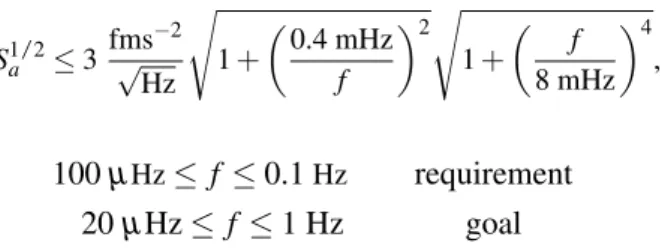
Second, any interferometric readout noise, that contaminates the test-mass to test-mass distance measurement. The level of this noise is given by equation 1.6. In these equation, the sensitivity requirement is set to 100µHz for more simplicity in testing. But the design aims to cover a wider frequency range, labelled goal in the equations.
Sa1/23 fms 2 pHz
s 1+
✓0.4 mHz f
◆2s 1+
✓ f 8 mHz
◆4
, and (1.5)
S1/2IFO10 pm pHz
s 1+
✓2 mHz f
◆4
, with (1.6)
100µHzf 0.1 Hz requirement 20µHz f1 Hz goal
The challenging technologies required to build LISA were successfully tested with the LISA Pathfinder Satellite. LISA Pathfinder demonstrated, that it is possible to place two test-masses in a nearly perfect free-fall condition, and measure their relative displacement precisely in space. The LISA Pathfinder mission is elaborated in the next section.
1.4 LISA Pathfinder
The LISA Pathfinder satellite [13] was a European mission, that was launched in Decem- ber 2015 towards its orbit around L1, the first Lagrange point of the Earth-Sun system, in a distance of about 1.5 million kilometers from the Earth, and it flew until July 2017.
1.4. LISA Pathfinder 7 The successful mission demonstrated the availability of the sophisticated technology requirements for LISA and paved the way for the future space-based gravitational wave observatory [14,15].
In the LISA Pathfinder mission two test-masses were placed in nearly pure free-fall condition, and they were followed by the spacecraft along their geodesic paths. Further- more, their relative displacement, which was the main mission observable, was monitored precisely by a laser interferometer. LISA Pathfinder was basically one of the LISA arms reduced to 38 cm distance between the test-masses in one single spacecraft. Although the short distance did not allow for gravitational waves measurements, it was sufficient to test the functionality of the different subsystems for LISA [16, 17]. Some of these subsystems, which are important for understanding the mission concept in the scope of this thesis are listed and explained as follows.
• Gravitation Reference Sensors
Each LISA Pathfinder test-mass was a 1.93 kg gold-platinum cube with a 46 mm side, surrounded by a set of electrodes, which were mounted on an electrode- housing with a gap of 2.9-4 mm to the test-mass on different axes. Each of these electrodes created a capacitor with the test-mass surface, which facilitated touch- free control and sensing of the test-mass position.
Position control was achieved by applying voltages to the electrodes. This generated an electrostatic field and consequently, an electrostatic force that was used to control the test-mass dynamics [16]. The control system is elaborated in section2.2.
Position sensing was based on the capacitive readout. Test-mass dynamics caused an imbalance in the gap between the test-mass and the opposing electrodes, which influenced the capacitance. By measuring the differential capacitance between the electrodes and the test-mass the position of the test-mass could be measured [18].
LISA Pathfinder achieved a sensing precision given by 1.8 nm/p
Hz for linear and 200 nrad/p
Hz for angular displacement down to 1 mHz frequencies [18].
A caging mechanism was implemented for mechanical fastening of the test-mass during the launch and releasing it in commissioning. A UV light discharge system was applied to remove the charge on the test-mass caused by cosmic rays [19].
These elements were placed in a vacuum chamber to shield the test-mass from disturbance forces, and together with the related electronics for actuation and sensing, they constructed the Gravitational Reference Sensors (GRS) [20]. The LISA Pathfinder GRS will be largely integrated into LISA.
• Optical Metrology System
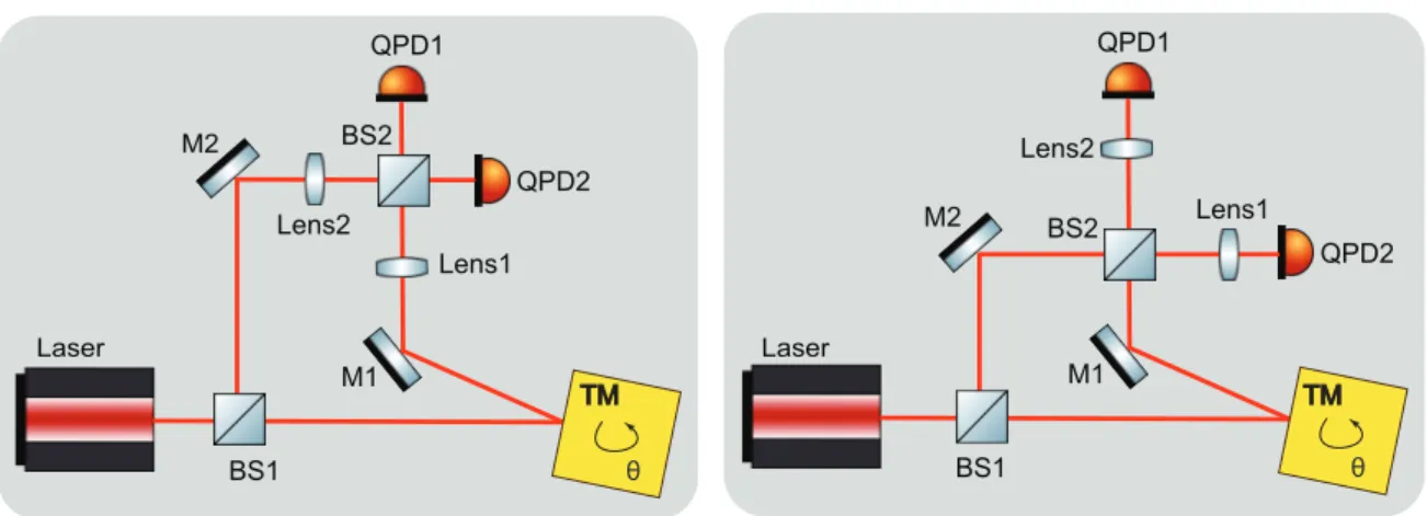
The Optical Metrology System (OMS) included among other sub-units an Nd:YAC NPRO laser with wavelength of 1064 nm and 35 mW, an optical bench, a laser modulator that produced two beams of slightly different frequencies necessary for the heterodyne interferometry, and two science interferometers. The first one was responsible for measuring the relative linear displacement of the two test-masses along the science axis x, that connected the center of the test-masses. It also measured the relative angular displacement of the test-masses aroundyandzaxes, using the Differential Wavefront Sensing (DWS) Method. The second science in- terferometer measured the relative linear and angular displacement of the drag free test-masses, also labelled TM1, with respect to the spacecraft [21]. More details
8 Chapter 1. Introduction about the drag free test-mass is provided in the next paragraph. OMS achieved the expected precision with a noise level below 9 pm/p
Hz and 20 nrad/p
Hz between 3 mHz and 30 mHz frequencies [17,14].
270 Hz, depending on the degree of freedom, which avoids the mixing of low-frequency electrical noise into force noise in the measurement band [5].
Voltages are simultaneously applied to all electrodes, with commanded carrier amplitudes adjusted to produce any desired force with amplitude up to a fixed limit—
referred to here as the actuation“authority”—while holding the resulting electrostatic force gradient (or stiffness) constant. Force noise associated with this electrostatic suspension depends on the applied force levels but also on the force and torque authorities [9]. To limit this noise contribution we have reduced the authority for the critical x and ϕ (rotation aroundz, see Fig. 2) degrees of freedom during science operations.
Our science signal is in the differential displacement of the two TM along the x axis, Δx≡x2−x1, and this is measured by a dedicated heterodyne laser interferometer [10–12]. A second interferometer measures the displace- ment of TM1 relative to the spacecraft, x1. Both interfer- ometers have quadrant diode wavefront sensing, allowing measurement of both TMϕ andηrotations aroundz andy (see Fig. 2), respectively.
The TMs and the spacecraft constitute a three-body dynamical system in which we control all 12 degrees of freedom of the relative motion of the TMs and spacecraft.
At frequencies below 1 mHz we also control the orientation of the spacecraft relative to the J2000 reference frame.
Describing the details of this system goes beyond the scope of this Letter[13]. Here we just recall the logic of the control scheme for the x axis. Along this axis the spacecraft is forced to follow TM1 to keep it in the center of its electrode housing. For this,x1is fed to a controller residing within the onboard computer. The controller commands a set of cold- gas micronewton thrusters to ensure the spacecraft follows TM1 (see Fig. 2). This scheme, called drag-free control [13], is also an essential element of the LISA spacecraft control, and is therefore one of the key elements under test.
A second control loop forces TM2 to stay at a fixed distance from TM1 and thus centered in its own electrode housing; we call this electrostatic suspension. The con- troller, which operates at low frequencies compared to the LPF measurement band, uses Δx as an error signal, and commands the electrostatic actuation system to generate the necessary forces on TM2. This controller is required because any static difference in force between the TMs would accelerate TM2 relative to TM1, eventually pushing it into contact with its electrode housing.
B. Comparing to LISA
Electrostatic suspension along the sensitive axis is not needed in LISA as the two TMs at the ends of the same arm can be followed independently by their respective space- craft along the direction of the laser beam [2]. This results in both TMs staying centered along the beam direction in their respective housings.
In LPF, this necessary applied control force must be subtracted from the measured acceleration to give the relevant Δg. The subtraction of the commanded force time series, gcðtÞ, and its calibration, is discussed in the next section. This also introduces potentially important actuation force noise, that is not present in LISA, into our LPF data.
Note that everywhere in this Letter forces are expressed per unit mass and that we treat signals as continuous, as the 10 Hz sampling frequency is much larger than the maxi- mum frequency of interest of about 0.1 Hz.
The electrostatic suspension is not the only difference with LISA. As all measurements and controls in LPF are performed relative to the spacecraft reference frame, the component of the centrifugal force from rotation around y andzis directly picked up as an effective differential force.
This force is quite relevant for frequencies below 0.5 mHz as the input to the attitude controller of the spacecraft is a set of autonomous star trackers with relatively high sensing noise of about10−3 rad= ffiffiffiffiffiffi
pHz
at 0.1 mHz. This noise causes a significant noisy angular velocity ΩnðtÞ relative to the local inertial frame. ΩnðtÞ adds to the quasistatic part, ΩqsðtÞ, of a few degrees per day, needed to keep the communication antenna pointed toward the Earth. As the centrifugal force is quadratic in the angular velocity, it acquires, to first order in Ωn, a noisy component propor- tional to ΩnðtÞΩqsðtÞ. Nominally, this effect will not be present in LISA where the two TMs at the end of each FIG. 2. A schematic of LPF. The figure shows TM1, TM2, and
the optical bench beam paths for measuring Δx and x1. The measurement of Δx drives the electrostatic suspension of TM2, which applies the necessary electrostatic forces by means of the electrodes represented by the four gold plates facing TM2.
All other electrodes surrounding the TMs are not shown.
The measurement of x1 drives the drag-free control loop that uses the micronewton thrusters to exert forces on the spacecraft.
The figure depicts thexandyaxes we use in this Letter, whilezis normal to the figure.
PRL 116, 231101 (2016) P H Y S I C A L R E V I E W L E T T E R S week ending
10 JUNE 2016
231101-4
FIGURE1.6: LISA Pathfinder scheme. The two test-masses are placed in a hollow electrode housing within one single spacecraft and their relative distance (labelledDxin the figure, andx12 in the text) is measured precisely by a laser interferometer. Furthermore, the position of TM1 is measured with respect to the spacecraft (x1). This is used by the DFACS, which apply the micro-newton thrusters to force the spacecrfat following TM1. Moreover, the position of the test-masses with respect to their electrode housing is measured by the capacitive sensors, which are the electrodes surrounding the test-masses. For sake of simplicity, only four electrodes around TM2 are shown in the figure. DFACS use the capacitive readout to control the position of TM2 within its electrode
housing.Credit:Armano et al [14]
• Drag Free Attitude Control System
In the LISA mission the two test-masses belonging to the same interferometer arm are located in different spacecrafts. In the LISA Pathfinder mission however, the two test-masses were placed in the same spacecraft. Due to the residual force gradients in the spacecraft environment, which caused a slow drift of the test- masses, it was impossible to keep both test-masses centred in their GRS electrode housing and simultaneously follow them along their geodesics. Therefore, only one of the test-masses, labelled drag-free TM or TM1, was continuously put in free-fall along the sensitive measurement axis,x, and the spacecraft was controlled using the micro-newton thrusters to follow TM1. This control system is called
1.5. Test-Mass Actuation and Position Sensing 9 drag-free control and it is also essential for the LISA spacecrafts. The other test- mass, labelled TM2, was actuated by the capacitive sensors in GRS, to follow the spacecraft and TM1. This control scheme is called suspension control loop and it is not foreseen for LISA, as the two test-masses belonging to the same interferometer arm are located in different spacecrafts and they can be followed along the sensitive measurement axis independently. This was the task of the Drag Free Attitude Control System (DFACS) [22]. Furthermore, The DFACS were responsible to keep the spacecraft pointing towards the sun and the antenna pointing towards the Earth by using the star trackers as sensors.
Figure1.6illustrated the LISA Pathfinder scheme and the interaction between the above mentioned subsystems. The main mission observable, labelledDg, was the differential stray forces acting on the two test-masses, calculated per unit mass.
Dg(t) =x¨12(t) +w22x12(t) + (w22 w12)x1(t) gc(t) gW(t) (1.7) In this equation,x12andx1are respectively the relative displacement between the two test-masses, and the displacement of the drag-free test-mass with respect to the spacecraft, measured by the science interferometers. x¨12 indicates the second time derivative or the relative acceleration between the test-masses measured by the interferometer. The parasitic stiffnessesw1andw2can be understood as spring constants per unit mass for oscillatory like force couplings between the test-masses and the spacecraft. The actuation forcegc(t)is the one commanded by the suspension control loop to keep TM2 centered in its electrode housing. The impact of actuation force error on Dg is analysed and discussed in chapter2. Finally,gw(t)indicates the centrifugal force that arose due to the fact, that the displacement measurements were performed in the spacecraft frame, which was a non-inertial frame causing fictitious forces when rotating alongy andz.
Nominally, actuation force and centrifugal force will not be present in LISA along the sensitive measurement axis [15].
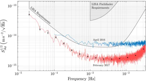
Shortly after starting the science measurements, the successful mission demonstrated a measurement sensitivity much better than the expected requirements, and by the end of the mission it achieved a performance even better than that of expected for LISA. This is demonstrated in figure1.7. Improvement of the performance was based on decreasing the Brownian noise by continuously venting the vacuum tank to space, and consequently reducing the gas pressure around the test-masses. Furthermore, a systematic source of noise caused by erroneous actuation force applied to TM2 was identified and compensated in post-processing the data. This is further elaborated in chapter2. Additionally, the effect of factious forces caused by spacecraft rotation were considered, and finally the data were cleaned by removing the quasi-impulse force events, called glitches, to achieve uninterrupted and long data series [15].
1.5 Test-Mass Actuation and Position Sensing
As mentioned in the previous section, the GRS are responsible for sensing the position of the test-mass in all degrees of freedom, and control its position to keep it centred in the electrode housing. Among others, the GRS performance is limited by the precision of actuation and also the precision of sensing. The relevance of actuation precision for the LISA Pathfinder and the LISA missions is explained in subsection1.5.1. Investigations and analyses of actuation precision and its impact on both missions shapes the first part of