Semantics of the Phase Model of Production: Formalization
Jürgen Ebert and Martin Schulze, University of Koblenz, Germany
Corresponding Author: M. Schulze
Universität Koblenz-Landau, Campus Koblenz, Institut für Softwaretechnik Postfach 201602, D-56016 Koblenz, Germany
+49-261-287 -2722 (J. Ebert) / -2703 (M. Schulze) / -2721 (Fax) {ebert,schulze}@uni-koblenz.de
http://www.uni-koblenz.de/ist/
Abstract
Syntax and semantics of most visual languages are not formally defined. But to build tools like editors or to use diagrams as input for a simulation algorithm, a formalization of the syntax and semantics is necessary to define which diagrams are valid and what is their meaning.
In this paper a method, developed in software engineering to formalize the semantics of visual languages, is applied to a visual language in process control engineering, namely the “Phase Model of Production”. In this approach class diagrams and constraints in aZ-like formal notation (EER/GRAL) are used as conceptual models to define the syntax of visual languages. Then, the semantics is defined operationally by abstract automata defined inZ, that make use of the syntax description. Two different semantics, for discrete processes and for continuous processes, are presented.
1 Introduction
1.1 Visual Languages
Visual languages are a means of communication often used in process control engineering, software engineering, as well as in other disciplines. Diagrams are used to describe models of parts of reality. They are used as a means for discussions between experts and laymen. They can be used to document existing systems or to specify planned systems. On the one hand diagrams are easy to understand, on the other hand they serve as a formal specification of a system. Examples for commonly used visual languages in the fields of process control engineering and software engineering are flowsheets [4], Petri nets [2], and the sublanguages of the Unified Modeling Language UML [3].
Many visual languages do not have a formal specification and are used unprecisely. This is not a problem per se, since for drafts one does not want to be plagued by strictness and one likes to sketch one’s ideas without restrictions. But if diagrams are used in a contract or in an instruction, one has to know exactly what is meant by them. Furthermore, to work efficiently with diagrams, one needs software tool support. To implement tools for visual languages, a precise formalization is needed, too. To build a visual editor a software engineer has to know exactly the syntax of the diagrams: which elements are used, how they may be connected, which further constraints must hold. For example, in Petri nets there are places, transitions, tokens and connections. Tokens may only be put on places but not on transitions, and the graph of places and transitions with their connections must be bipartite. To simulate the behaviour of a modeled system one must also know the exact meaning, the semantics of the diagrams. For example, to simulate a system by means of a Petri net, one has to know, under which conditions the transitions fire and how the tokens are moved between places thereby.
In this paper, we demonstrate a method to formalize the semantics of visual languages to put them onto a math- ematical foundation [5]. The method has been used successfully to formalize the semantics of object-oriented languages in the field of software engineering [10]. We apply this method to a visual language often used in process control engineering, the “Phase Model of Production”.
1.2 Phase Model of Production
The Phase Model of Production (PMP) [8], [1] is a visual language to specify production processes and other processes. It was developed from flowsheet diagrams by adding markers for products between the processes.
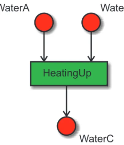
Figure 1 gives a very simple example, a processHeatingUpconsuming two productsWaterAandWaterBand producing a productWaterC. The symbols used in Phase Model diagrams, their application areas, advantages, and disadvantages are discussed in [7] in detail.
HeatingUp
WaterA WaterB
WaterC
Figure 1: Simple Example of a Phase Model of Production
A formal semantics for the Phase Model of Production does not exist yet. In fact, the diagrams are used for different scenarios that are not distinguished in the syntax. For instance, the flow of products between the processes can either be discrete or continuous. Furthermore, a diagram can be seen either as a kind of dataflow diagram or as a kind of state transition diagram. In a cooperation between the Lehrstuhl für Prozessleittechnik (RWTH Aachen, Germany) and the Institut für Softwaretechnik (University of Koblenz-Landau, Germany) several variants of the semantics have been discussed and formally defined. In this paper we will introduce two different semantics to give an impression of the spectrum covered by this approach.
1.3 Contents
The paper is organized as follows: In chapter 2 conceptual modeling with class diagrams and a constraint language is introduced as a method to define the syntax of visual languages, and this method is applied to the Phase Model of Production. In chapter 3 abstract automata are introduced as a method to define the semantics of visual languages. The method is applied to formalize two semantics, one dataflow like semantics and one state transition like semantics. In chapter 4 we draw a conclusion and explain what has to be done yet.
2 Formalization of Syntax
2.1 Conceptual Modeling
Our approach to formalize the syntax of (visual) languages is to use class diagrams as meta-models of the abstract syntax of the language [6]. We do not need to define the shapes of the symbols and their spatial arrangement.
Classes define the constituents of the diagrams. Associations define the allowed relations between these con- stituents. Attributes of classes and associations define the possible properties of the constituents and their rela- tions. Further constraints are expressed as multiplicities of associations and by additional clauses in a language called GRAL.
Formally, a class diagram defines a set of graphs. Any correct diagram of the modeled visual language can be represented as a graph that is a member of that set. In our approach to define the semantics of a visual language we use these conceptual models as a basis for the semantics formalism.
2.2 Application to Phase Model Diagrams
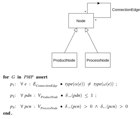
The conceptual model of Phase Model diagrams is shown in figure 2. Phase Model diagrams consist of nodes (Node) which represent either processes (ProcessNode) or products (ProductNode). They are connected by flows (ConnectionEdge). The class diagram is extended by three GRAL-constraints: There must not be
any flow connections between the same kind of nodes (p1), no product may be consumed by more than one process (p2), and every process consumes at least one product and produces at least one product (p3).
ProductNode ProcessNode Node
*
*
ConnectionEdge
for G in PMP assert
p1: 8 e : EConnectionEdge type((e)) 6= type(!(e)) ; p2: 8 pdn : VProductNode Æ*(pdn) 1 ;
p3: 8 pcn : VProcessNode Æ*(pcn) > 0 ^ Æ(
(pcn) > 0 end .
Figure 2: Conceptual Model of Phase Model Diagrams
3 Formalization of Semantics
3.1 Abstract Automata
Our approach to formalize the semantics of (visual) languages is to map diagrams to abstract automata. The abstract automata serve as an operational semantics for the visual language [5]. We define these abstract automata using the specification languageZ1[9]. A definition of an abstract automaton has four parts.
Global definitions are the basis for the other parts. They define the level of abstraction of the semantics definition.
The Configuration schema defines the state space of the automaton.
The Delta schema defines the transitions from one state to the next.
The Init schema defines the set of start states of the automaton.
All parts can have references to the abstract syntax description by using properties of the syntax graph.
3.2 Application to Phase Model Diagrams of Discrete Processes
Phase Model diagrams can be used to describe systems, in which discrete individual products flow from one process to another. The processes may consume, change, and produce the products and are activated step by step.
See [7] for an example.
1We assume some basic knowledge aboutZ. A very short summary of the usedZ-concepts is given in the appendix.
Global Definitions (1)
We assume the existence of a universe PRODUCT, the set of all possible products.
[PRODUCT]
Values of product attributes express properties of products. The concrete attributes depend on the kind of product, but here we ignore this fact. We assume the existence of a universe ATTRIBUTE of all possible attribute identifiers and of a universe VALUE of all possible values.
[ATTRIBUTE;VALUE]
A mapping PRODUCT STATE from attribute identifiers to values characterizes the state of a product.
PRODUCT STATE==ATTRIBUTE!77 VALUE An example for a PRODUCT STATE is given in figure 3.
Figure 3: A PRODUCT STATE
Configuration
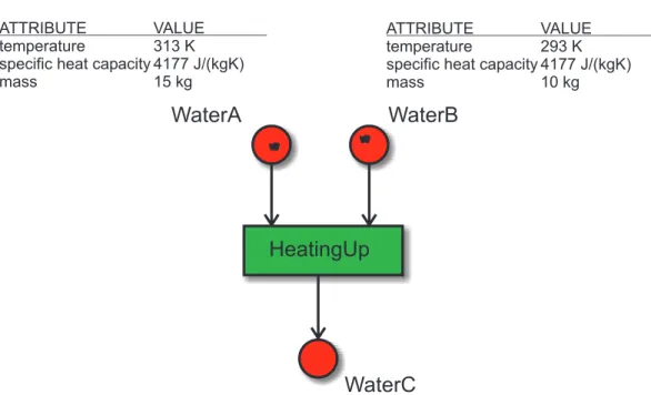
A state of a system described by a Phase Model diagram is characterized by the products in the system, their allocation to product nodes and their current properties expressed by the values of their attributes.
ConfigPMP Discrete
products:FPRODUCT
allocation:VProductNode77 PRODUCT
currentProperties:PRODUCT !77 PRODUCT STATE ran allocation=dom currentProperties=products
products is the set of all products existing in a Phase Model diagram at the given state. allocation describes which product lies on which product node. On every product node there may be one product at most, and every existing product must lie on a product node. currentProperties maps a product state (in terms of attribute value pairs) to each product.
Figure 4 sketches a state of the example diagram depicted in figure 1.
Global Definitions (2)
The knowledge about the processes that are performed on a process node is not specified in a Phase Model diagram. To describe the semantics one needs to supply the transformation function for each process node which defines the behaviour of the respective processes.
transform:VProcessNode!
((EConnectionEdge!77 PRODUCTPRODUCT STATE)
!(EConnectionEdge!77 PRODUCTPRODUCT STATE))
8pcn:VProcessNode
first(jdom transform(pcn)j) (pcn)^ first(jran transform(pcn)j)+(pcn)
transform is a function that provides to every process node the transformation function of the processes that are performed on it. The transformation function describes which products in which state lie on the output product nodes of the process node after executing the process, depending on the states of the products on the input product nodes. To perform a simulation of a system, concrete transformation functions for all process nodes have to be provided. Figure 5 sketches an extract of an exemplary transformation function.
HeatingUp
WaterA WaterB
WaterC
ATTRIBUTE VALUE
temperature 313 K specific heat capacity 4177 J/(kgK)
mass 15 kg
a ATTRIBUTE VALUE
temperature 293 K specific heat capacity 4177 J/(kgK)
mass 10 kg
a
Figure 4: A State of the Example Phase Model of Production
HeatingUp
out1: temperature= massin1temperaturein1 +massin2
temperaturein2
massin1 +massin2
+
8000W100s
(massin1 +massin2
)cin1
mass=massin1
+massin2
c=cin1
ProcessX out1: out2:
Figure 5: Extract of a transform function
Delta
In the discrete case a state change of the system means executing one process on a process node, thereby consum- ing the products on its input product nodes, and producing products on its output product nodes according to the transformation function.
DeltaPMP Discrete
ConfigPMP Discrete
pcn:VProcessNode
LET
output(pcn)==
transform
(pcn)
(fe: (pcn)(e7!(allocation((e));currentProperties(allocation((e)))))g) IN
products0=
(productsnallocation(j (pcn)j))[first(joutput(pcn)(j+(pcn)j)j) allocation0=
( (pcn)Callocation)[(fe:+(pcn)(!(e);first(output(pcn)(e)))g currentProperties0=
products0C(currentPropertiesfe:+(pcn)output(pcn)(e)g END
Executing a process pcn changes products, allocation, and currentProperties in a straightforward manner. products0, the set of products in the system after execution, is the old set products without the consumed products and ex- tended by the produced products of pcn. allocation and currentProperties are changed accordingly to reflect the change.
Init
A system defined by a Phase Model diagram may be started in any valid state.
InitPMP Discrete
ConfigPMP Discrete
3.3 Application to Phase Model Diagrams of Continuous Processes
An alternative view on systems is given if Phase Model diagrams are interpreted as state transition descriptions.
These kinds of descriptions occur for instance if a continuous flow through the system is modeled and processes are executed simultaneously. See [7] for an example.
Global Definitions
Because in the continuous case the products do not have an identity, they need not be modeled explicitly. The universe PRODUCT is not needed anymore and transform has a simpler signature.
transform:VProcessNode
!(EConnectionEdge!77 PRODUCT STATE)
!(EConnectionEdge!77 PRODUCT STATE)
8pcn:VProcessNode
dom(jdom transform(pcn)j)=f (pcn)g
^dom(jran transform(pcn)j)=f+(pcn)g Configuration
Due to the elimination of PRODUCT, the state of a system is now characterized by currentProperties alone.
products and allocation are not needed anymore.
ConfigPMP Continuous
currentProperties:VProductNode!PRODUCT STATE
Delta
To define the transformation process of the continuous case a clock pulse is still needed. But because there are no products to be removed or created, it only has to be modeled how the states of the output product nodes currentProperties0of all processes depend via transform on the states of the input product nodes currentProperties one time step before.
DeltaPMP Continuous
ConfigPMP Continuous
8pcn:VProcessNode
fe:+(pcn)e7!currentProperties0(!(e))g
=transform(fe: (pcn)e7!currentProperties((e))g) Init
Like in the discrete case, a system may be started in any valid state.
Init PMP Continuous ConfigPMP Continuous
4 Conclusion
A method to formalize the semantics of visual languages by abstract automata on the basis of a conceptual model was presented and used to define two different kinds of semantics for the Phase Model of Production. The presented semantics have a similar structure, so it is easy to see their differences. All semantics postulate the existence of a transformation function for the processes. If a concrete transformation function for a modeled system is given, it would be possible to generate a simulation tool for the system.
The presented semantics are only a part of a broad spectrum of possible semantics. Many more have been dis- cussed in the cooperation between the project partners.
E.g: the presented semantics for continuous processes assumes that all processes have the same dead time, i.e.
the attribute values at the output product nodes of all processes only depend on the attribute values at the input product nodes exactly one time step before. This is not realistic, so a more sophisticated semantics was developed, that is not presented here. This semantics allows different dead times for each combination of input and output product nodes of all processes and it even allows dependencies to more than one time step in the history of an input process node. The idea is to assign to each product node his history as a sequence of product states and to expand transform such that it takes into account all states of this history.
Another variant of the presented semantics was developed for stationary systems. In this case the dead time is0 and the attribute values of the output product nodes depend on the values of the input product nodes at the same time. Such a system never does change its state.
Further work is being done to formalize a semantics of systems that consist of discrete and continuous processes simultaneously. Therefore buffers and transitions between both kinds of processes have to be modeled.
Acknowledgement
The authors would like to thank Ulrich Epple, Michael Heeg, and Ulrich Werr for a very productive cooperation that lead to this paper.
Summary ofZ
Z[9] is a concise mathematical notation based on predicate calculus and set theory.
Structured data may be defined using schemas. A schema consists of some declarations describing the components of a composite structure and some predicates.
S
<declarations>
<predicates>
By the declarations variables are bound to elements of sets. The predicates add constraints, that the variables should fulfill. An axiomatic definition introduces some global constants in an analogous manner.
<declaration>
<predicates>
Sets may be introduced as given sets as in[X]or they may be built by expressions such asPX (FX) as powersets (finite powersets). For two sets X and Y, X ! Y (X !7 Y, X !77 Y, X Y) denotes the set of all total (partial, finite partial, injective) functions from X to Y. dom f (ran f ) delivers the domain (range) of function f . XCf (XCf ) returns the function derived from f by restricting its domain to (reducing its domain by) X. fg overrides f on the domain of g by g. Functions may be applied on sets by using(jandj)as parentheses.
Using i == e anyZ-expression e may be bound to an identifier i. Using LET i == e IN e0 END such an abbreviation definition may be made local to another expression e0.
A schema may be used to describe the states of a system. If a schema defines transitions between states, the components of the new states are primed by a dash symbol. S introduces the components of S in an unprimed and a primed version.
In GRAL [6]Z is used to describe graph properties. Here V (E) denotes vertex (edge) sets. For a given vertex v, (v)describes its adjacent vertices, and(v)its incident edges. Æ(v)returns its degree. For an edge e,(e) (!(e)) stands for its start (end) vertex.
References
[1] Wolfgang Ahrens and Martin Polke. Netzmodelle als systemtechnische Informationsbasis für die Prozeßleit- technik. at, 37(3):94–144, 1989.
[2] Bernd Baumgarten. Petri-Netze, Grundlagen und Anwendungen. Spektrum, Heidelberg, 2nd edition, 1996.
[3] Grady Booch, James Rumbaugh, and Ivar Jacobson. The Unified Modeling Language User Guide. Addison Wesley, Reading, 1999.
[4] DIN 28004. Fließbilder verfahrenstechnischer Anlagen. Beuth, Berlin, May 1988.
[5] Jürgen Ebert and Roger Süttenbach. Integration of Z-Based Semantics of OO-Notations. In Jan Bosch, editor, Object-Oriented Technology, volume 1357 of Lecture Note of Computer Science, pages 173–177.
Springer, Berlin, 1997.
[6] Jürgen Ebert, Andreas Winter, Peter Dahm, Angelika Franzke, and Roger Süttenbach. Graph Based Mod- eling and Implementation with EER/GRAL. In Bernhard Thalheim, editor, 15th International Conference on Conceptual Modeling — ER’96, volume 1157 of Lecture Note of Computer Science, pages 163–178.
Springer, Berlin, 1996.
[7] Michael Heeg and Ulrich Epple. Semantics of the Phase Model of Production: Application. In Inge Troch and Felix Breitenecker, editors, Proceedings of MATHMOD 2003, to appear 2003.
[8] Martin Polke. Prozessleittechnik. Oldenbourg, München, 2nd edition, 1994.
[9] J. Michael Spivey. The Z Notation: A Reference Manual. International Series in Computer Science. Prentice Hall, Hemel Hempstead, 2 edition, 1992.
[10] Roger Süttenbach. Formalisierung visueller Modellierungssprachen objektorientierter Methoden. PhD the- sis, University of Koblenz, 2001.