Working Paper
Design of slender reinforced concrete frames
Author(s):
Aas-Jakobsen, Knut Publication Date:
1973
Permanent Link:
https://doi.org/10.3929/ethz-a-000674501
Rights / License:
In Copyright - Non-Commercial Use Permitted
This page was generated automatically upon download from the ETH Zurich Research Collection. For more information please consult the Terms of use.
ETH Library
Design of Slender Rein¬
forced Concrete Frames
YKnutAas-Jakobsen
November 1973 Bericht Nr. 48
BirkhauserVerlag Basel und Stuttgart Institutfür Baustatik ETH Zürich
Design of Slender Reinforced Concrete Frames
von
Dr.sc.techn. Knut Aas-Jakobsen
Institut für Baustatik
Eidgenössische
Technische Hochschule ZürichZürich November 1973
FOREWORD
The two main
problems
in theanalysis
of slender reinforced concrete framesare the influence of the
displacements
on theequilibrium
(second ordertheory)
and the non-linear material behavior of the concrete and steel.The author has made a
general study
of theanalysis
anddesign problem.
Hedeveloped
apractical design
method and tested the aecuracyagainst
a pre-viously developed general Computer
program for theanalysis
of such frames (Bericht Nr. 45, Institut für Baustatik, ETH-Zürich, Januar 1973).In its
present
form thestudy
constitutes a basis for thedevelopment
ofpractically applicable Computer
programs. Furthermore it can serve in the formulation ofsimplified design
rules for routineproblems
in thedesign
of reinforced concrete columns.
The author has
prepared
thisstudy
inpartial
fulfilment of his doctoral work at the Institute of StructuralEngineering.
Zürich, August
1973 Prof. Dr. B. ThürlimannCONTENTS
Page
1. Introduction 7
1.1
Objectives
71.2
Glossary
71.3 Outline 8
1.4
Background
92. Basis of the Methods 16
2.1 Determination of a
point
on the realload-displacement
curve 162.2 Elastic frame
analysis
162.3 Cross sectional
analysis
173. Frame
Analysis
193.1 Procedure 19
3.2 Assumed material
properties
234.
Design
Method 274.1
Introductory
remarks 274.2 General
design
method 274.3
Simplified design
method 324.4 Procedure 34
4.5
Design
criterion 364.6
Special
cases 405.
Aecuracy
of thesimplified design
method 435.1
Types
of errors 435.2 Errors due to lack of "middle" strain
equality
435.3 Errors due to lack of "curvature"
equality
455.4 Errors in the estimated creep effect 54
6.
Design Examples
586.1 Tail
bridge pier
606.2 Arch 67
6.3 Tail
building
67Appendix
A2 82Appendix
A3 88Summary
91Zusammenfassung
92Resume 92
Notation 95
References 98
INTRODUCTION
1.1
Objectives
The
present investigation
is concerned with theanalysis
anddesign
ofslender reinforced concrete frames
subjected
to short-time and sustainedloading.
Thestudy
is limited toplane
frames.The
objectives
of thisinvestigation
are- the
development
of a method which enables the determination of the maximum loadcapacity
of a slender frame withgiven
cross sectionsand reinforcements. This method will be termed a frame
analysis.
- the
development
of a methodwhereby
cross sections and reinforcementscan be determined for a frame
subjected
togiven
loads. This method will be termed adesign
method.Although
the basicassumptions
areessentially
the same for both the ana¬lysis
and thedesign,
some differences do exist in the number ofsimpli¬
fying assumptions
made. The former will be formulated asaccurately
aspossible
while in the latter exactness is sacrificed for the sake of sim¬plieity.
1.2
Glossary
The
key
terms andexpressions
used in thisinvestigation
are defined asfollows:
§!§§tic §D§^y§i§
^s used to determine elasticforces,
M and N, and thecorresponding
strain distribution for all sections of the frame. Thegiven properties
aregeometry
of the frame, loads andrigidities
for all members.The
equilibrium equations
in the elasticanalysis
are formulated for thedeformed frame. The
resulting
elastic forces, therefore, include secondorder effects.
Cross_sectional analysis
is used to determine inelasticforces,
M. and N., which are the resultants of the stresses over a cross section. Given pro¬perties
are cross section,reinforcement,
materialproperties
and strain distribution. In the cross sectionalanalysis
the real behavior of the materials are considered.M = M.
l N = N.
(1.1)
§train_eguality
is satisfied for a section when the strain e calculated inthe elastic
analysis
isequal
to the strain e. used in the cross sectionalanalysis.
The strain isgiven by
(seeFig.
3, page 18)1
e = e - (—) • z for the elastic analysis
m r J
1
e.= e .-(—)• z for the cross sectional analysis
l mi r. J
l
where
e , e . m mi
are the axial strain at the level of the
system
lineVr, Vr. are the curvatures
is the distance from the
system
lineStrain
equality
is definedby
e = e .
m mi
1=1
r r.
(1.2)
1.3 Outline
The two main difficulties in the
analysis
anddesign
of slender reinforced concrete frames are due to- the influence of the
displacements
on theequilibrium
of the frameproducing
a"geometrical non-linearity".
- the non-linear stress-strain-time relations for the materials
causing
a "material
non-linearity".
The two non-linearities are treated
separately
of each other. Thegeometri¬
cal
non-linearity
is considered in an elasticanalysis,
and the material non-linearity
is taken into account in a cross sectionalanalysis.
The two non-- 9
linearities are
coupled through
therequirements
of forceequality
(Eq.
1.1) and strainequality (Eq.
1.2). Theseaspects
are considered inChapter
2.The elastic
analysis,
the pross sectionalanalysis
and the force- and strainequalities
outiined inChapter
2, are the basis for both frame ana¬lysis
anddesign. Chapter
3 shows how these can beapplied
in a frame ana¬lysis.
Theprocedure
used in thedesign
method is discussed inChapter
4.A
general design
method which has the same aecuracy as the frameanalysis,
is outiined. The
procedure
is thensimplified
togive
a morepractical design
method.The aecuracy of the
simplified design
method isinvestigated
inChapter
5.Three realistic
design problems
inChapter
6 demonstrate theefficiency
ofthe
proposed design
method.1.4
Background
The foundation for the
understanding
of theload-carrying capacity
of com¬pression
members and the associatedphenomenon
ofinstability
is thetheory
of Euler (1759)
[1]*
for the bifurcation load P of a concentrically loadede J
elastic column:
P
tt2
• EI*2
Euler was the first to realize that a column could reach failure not neces-
sarily by crushing,
but alsoby instability arising
from deformations.At the
beginning
of ourCentury,
the Eulertheory
was extended to columns with non-elastic materials. Two basichypothesis
were formulated, known as thetangent
modulus(Engesser)
and the reduced modulus(Engesser-
von Kar¬man) theories. The former
gives
the load where bifurcation starts, and the latter a theoretical maximum value which can never be reached.A most
signifieant
contribution to thestudy
ofeccentrically
loaded columnswith non-elastic material
properties
was the work of von Karman[2]
in 1910.He
presented
ageneral
non-linearanalysis
based on the actual stress-strainrelationship
of the material.Assuming
thatplane
sections remainplane,
*) Numbers in braekets refer to references listed at the end.
ture
relationship.
From numericalintegration
of the curvaturealong
thecolumn
length,
the deflectionshape
of the column was determined.Some
representative investigations
about slender reinforced concrete col¬umns and frames are summarized in
Fig.
1. The survey is notcomplete,
butit is believed to
represent
some of the moreimportant developments.
Thestudies have been classified
according
to thetype
of structure, theshape
of the deflection curve, the load
history
and theapplied
creep law.Most
investigations
have concentrated on thehinged
columnsubjected
to anaxial load with constant end eccentricities. Broms
[4]
andPfrang
and Siess[5]
introduced elasticSprings
with infinite momentcapacity
at the endsof the column in order to simulate the effect of
connecting
beams. Breen[6]
and Manuel and
MacGregor [10]
studiedsimple
braced frames where the real behavior of the beams was taken into account. Aas-Jakobsen and Grenacher[14]
developed
a method tostudy
anytype
ofplane
frames.The
geometrical non-linearity
has either been taken into accountby assuming
the form of the deflection curve (for instance a cosine wave) or
by
deter¬mining
the real curve. The formerprocedure requires considerably
less nume¬rical work.
Three
types
of load histories were considered in thepast.
These were (seeFig.
2) :1. Short-time
loading
- the load increasesinstantaneously
fromzero until maximum load
capacity
isreached.
2.
Long-time loading
- the load is increasedinstantaneously
to a desired load level and then sus-
tained until
instability
occures.3.
Long-short-time loading
- the load iskept
constant over a defined timeperiod
and then raised instantane¬ously
to maximum loadcapacity.
The first studies of the influence of creep treated the
long-time loading
case
[7], [8], [9].
In laterinvestigations
thelong-short-time loading
has
caught increasing
interest [10], [13],[15].
This latterrepresenta¬
tion is believed to be a more realistic Simulation of the actual
loading
conditions than the
long-time loading.
Thelong-short-time loading implies
that the effect of creep is taken into account at the
working
load level,structure
deflection
curveloadhistory
creep lawcomments
Baumann,1934 [3] hinged
andclamped
columnrealshort-
time Broms, 1956 [4] restrained
columncosine
wavelong- time
reduced modulus Pfrang and Siess,
1961[5] restrained
columnrealshort- time Breen, 1962 [e] braced frame
realshort- time Warner
andThürlimann, 1963 [7J hinged
columncosine
wavelong- time
rateof
creepI-section with
zerowebthickness Mauch
andHolley, 1963 [8] hinged
columncosine
wavelong- time
rateof
creepGreen, 1966 [9] hinged column
reallong- time
reduced modulus Manuel
andMacGregor, 1966 [lü]
braced frame
reallong-short- time
rateof
creepAroni,1967 [ll] hinged column
realshort- time prestressed column Oelhafen, 1970 [12] hinged
columnreallong- time
~rate
of
creepstudied influence of
thevariance of material and sectional properties
onthecolumnbehavior Hellesland, 1970 [13] hinged column
cosine
wavelong-short- time
*•
general rheological. model for
concreteAas-Jakobsen and Grenacher, 1972 [14j general frame
reallong-short- time
rate
of
creepFig. 1: Review of previous investigations
long- time long-short-time
J
/
w
p-
\
\
T,
W
Fig. 2: Types of load histories
and that the failure load is an instantaneous overload (such as wind and
earthquake).
The assumed stress-strain relations for concrete under short-time load dif- fer
only slightly
in thesurveyed
papers. On the other hand the creep of concrete has been considered in several different ways.Broms
[4]
and Green[9]
used the reduced modulus method. In this method the increase of strain under sustained load is taken into accountby increasing
all strains in the short-time stress-strain
diagram by
the same factor (seeFig.
14, page 32). Thisimplies
that the Variation of concrete stress underthe
long-time period
isneglected.
The rate of creep method (which is
equivalent
to theDischinger
law) is per-haps
the method which has been used mostfrequently
to estimate the effectof variable stresses. The most
complete description
of therheological
be¬havior of concrete seems to be the one
by
Hellesland[13].
He also consi-ders the increase in
strength
due to continuedhydration
of thecement,
andthe decrease in
strength resulting
at stresses above a certain "critical"stress.
All
investigations
reviewedreport
a closeagreement
betweenanalysis
andtests. Oelhafen [12]
compared
the theoretical confidence limits of the load-displacement
curves with test results [15], and concluded that the Statisti¬cal
analysis
confirmed thereliability
of thecomputation
method.13
Most studies in the field of slender reinforced concrete columns and frames have been concerned with the behavior and maximum load
capacity
of suchstructures. The
design problem,
which is theprime
motive of this research, has attractedrelatively
little interest.Thus,
a gap seems to exist between thepresent knowledge
about the behavior of slender concrete structures on one hand, and thepractical
Solution to thedesign problem
on the other.With few
exceptions
the firstdesign
methods for slender reinforced concretecolumns were based on either the "u-method"
[3], [16]
or the American re¬duetion factor method based on the
investigation by
Broms[4].
Both methods reduee thedesign
of a slender column todesign
of a section. In the "id-method" the axial force and the first order moment are
multiplied by
a w-factor
greater
than 1,0. In the American method the allowable axial force for the section ismultiplied by
a R-factor less than 1,0.A severe
shortcoming
of these earlierdesign
methods is that the same ec-centricity
is maintained for the section and the column. This is contradic-tory
to the actual behavior of slender columns where the reduetion in loadcarrying capacity
is causedby
the increasedeccentricity
due to the de- flections.The Swiss SIA code
[17]
(1955) introduced an increasedeccentricity.
Re¬written in the form for ultimate load
design
ei 1 1 -
*
N
er
e is the total
eccentricity
for the sectionei is the first order
eccentricity
from external loadsN is the ultimate axial force
N is the maximum force for the
centrically
load column.er
About 1960 the CEB-recommendations
[18]
introduced ultimate loaddesign
and an additional moment
approach
for slender columns.In the last years the German DIN and the American ACI codes have been re-
vised, both
introducing
ultimate loaddesign. According
to the DIN codeslender columns are
designed
for an additional moment, and the ACI code in¬creases the first order moment
using
a similarexpression
as the SIA codereferred to above.
The
design procedure
for the codesjust
mentioned may be summarized as follows:1. Determine the moments and axial forces from a first order elastic
analysis.
2. Determine the elastic
buckling length
of each column.3. Account for the slenderness effect
by increasing
the firstorder moments.
4.
Design
the cross section.The sources of errors in this
procedure
are:- The first and second
step imply
anassumption
of the El-values. Theseare often calculated on the basis of the net concrete cross section
although
it is well known that this is a ratherrough approximation.
Therigidity
alsodepends
on the reinforcement, the moments and axialloads,
and asatisfactory
El-value must take this into account.- The third
step
is based on theassumption
that the increase in momentdue to the deflection of the structure can be related to the elastic
buckling length
of each individual column. This is anassumption
oftenused in the
theory
of elasticstability.
- In the third and fourth
step
thestability problem
is reduced to the pro¬blem of a short column associated with material failure under excessive strains in steel and concrete. Slender structures
usually
fail under muehsmaller strains, i.e. before the material failure state is reached. Gen-
erally,
adisagreement
between actual failure state anddesign
stateexists in the
approximate
methods reviewed.In addition to the
simplified design
methods outiined above, most codes en-courage the use of more
comprehensive
methods which consider thesecondary
moments and the actual material response.
A
design
methodattempting
a betteragreement
with the real behavior is the so called "model column" methodpresented
in theCEB-buckling
manual[19].
The method is based on an assumed form of the deflection curve and the ac¬
tual stress-strain relations, and is restricted to cantilever columns.
Beck and Bubenheim
[20] developed
adesign
method forplane
frames undershort-time loads. Their method is based on an elastic second order ana-
15
lysis
and a cross sectionalanalysis
which determines the "secantrigidi-
ties" (the secant
rigidity
is the moment determined in a cross sectionalanalysis
divided with thecorresponding
curvature). Cross sections and re¬inforcements must be known in advance. The maximum load
capacity
is deter¬mined in a
"step by step" procedure
where the secantrigidities
are deter¬mined
iteratively
at eachstep. By
means of aspecial algorithm
the rein¬forcement is
changed
until the calculated maximum load and thegiven design
load coincide.
2. BASIS OF THE METHODS
2.1 Determination of a
point
on the realload-displacement
curveA
point
on theload-displacement
curve is definedby equilibrium
and com¬patibility.
In the case of slender concrete frames both thegeometrical
and material
non-linearity
must be considered. These twonon-linearities,
which combine to affect the overall structural response, can
conveniently
be considered in two
steps:
1. The
geometrical non-linearity
is accounted for in an elasticsecond order frame
analysis.
Thisanalysis
is based ongiven
loadsand assumed
rigidities
andyields
elastic forces, M and N, andcorresponding strains,
em andVr,
for all sections.Equilibrium
and
compatibility
are satisfied in the elasticanalysis.
2. The material
non-linearity
is taken into account in the cross sec¬tional
analysis through
the use of the real stress-strain-time relations. For a given° straindistribution,
e . and Vr., the in-mi l
elastic forces, M. and N., can be determined.
A
point
on the realload-displacement
curve is now definedby
forceequali¬
tyJ (M = M.; N = N.) and,
similarly,
strainequality
(Vr = Vr.; e = £ .)ii im mi
for all sections. It should be
recognized
that the mainproblem
involvedin the frame
analysis
anddesign
method is tosatisfy
the force and strainequalities.
2.2 Elastic frame
analysis
The elastic analysisJ yieldsJ elastic forces, M and N, and
strains,
em andm
Vr, for
given geometry
of the frame, loads andrigidities.
Theanalysis
isperformed by
means of the finite element method. A detaileddescription
of this method isgiven
inAppendix
A1. A short review ispresented
in thefollowing.
The frame is divided into beams and columns which are termed members. The members are subdivided into elements. The elements are connected at their ends, the so-called nodal
points.
Thedisplacements
of these nodalpoints
are the unknowns. Based on the
load-displacement
relation for each element,the
load-displacement
relation for the whole structure isdeveloped,
and maysymbolically
be written17 -
([KJ
+[K2])-{w>
={P}
(2.1)[Ki]
is the first order stiffness matrix[K2]
is thegeometrical
stiffness matrix{w}
is the unknowndisplacement
vector{P}
is the load vectorAn elastic
analysis
may be of first or second order. In a first order ana¬lysis
theequilibrium equations
are formulated for the undeformedstructure,
and the
geometrical
stiffness matrix[K2]
inEq.
2.1 vanishes.In a second order
analysis
theequilibrium equations
are formulated for thedeformed structure. The additional stiffness matrix
[K2]
isdependant
on theaxial forces N in the elements. The axial forces
depend
in turn of the ex¬ternal loads. A non-linear relation between
displacements
and loads results.Due to the fact that the
geometrical
stiffness matrix[K2] depends
on theaxial forces in the elements, an iterative
procedure
results. Based onassumed values of N, new axial forces are determined. The
procedure
is re¬peated
until assumed and calculated axial forces coincide.2.3 Cross sectional
analysis
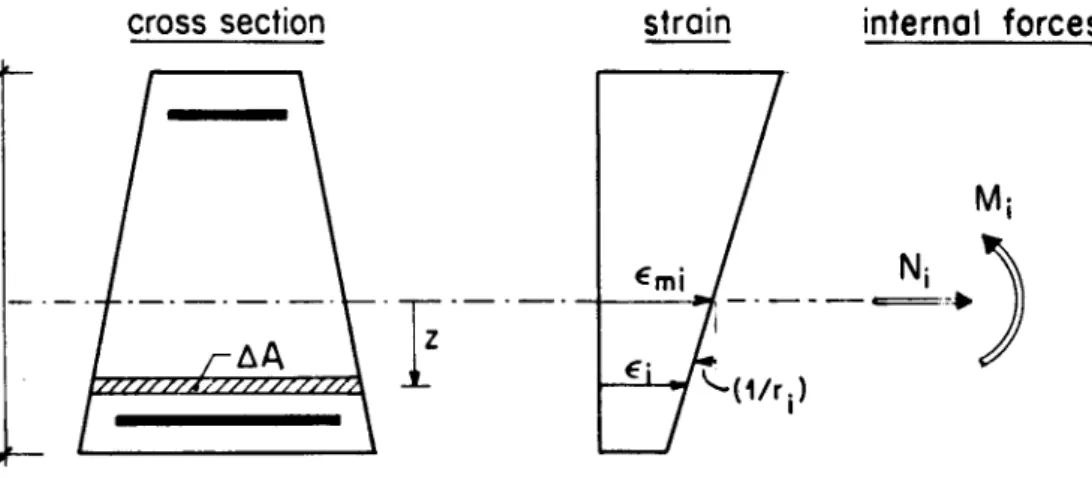
The resultant inelastic forces, M. and N., are determined from
given
strain distribution, cross section, reinforcement and materialproperties
(seeFig.
3)M. = E o • z • AA 1
N. = E o • AA (2.2)
1
The strain e. is assumed to be
positive
when in tension and to belinearly
distributed over the section. Then
e. = e .-(—)• z (2.3)
1 mi r.
e . is the axial strain at the level of the
system
linemi
Vr. is the curvature
is the distance from the
system
linecross
section
/ ^AA \
2strain internal forces
Ni
Fig. 3: Cross section, strain distribution and forces
The stress a
depends
on the strain e.a = f(e.) (2.4)
The
adopted
stress-strain relations are different in the frameanalysis
anddesign method,
and are outiined in theirrespective chapters.
19
FRAME ANALYSIS
3.1 Procedure
The purpose of the outiined frame
analysis
is to determine the maximum load for aplane
frame withgiven
cross sections and reinforcements. To be able to account for anabritrary
loadhistory,
astep by step procedure
is used.The increase of stress is related to the increase of strain and time, and loads and time are increased in small increments. A
Computer
program wasdeveloped
inconjunetion
with thisstudy,
and method and program are des¬cribed in detail in
[14].
However, as it forms an essential base for thisstudy,
a briefdescription
will begiven
below.The maximum load
capacity
of a frame withgiven
cross sections and rein¬forcements is considered in two
steps.
First, apoint
on theload-displace¬
ment curve is determined, and second, it is checked whether this
point
re¬presents
the maximum loadcapacity.
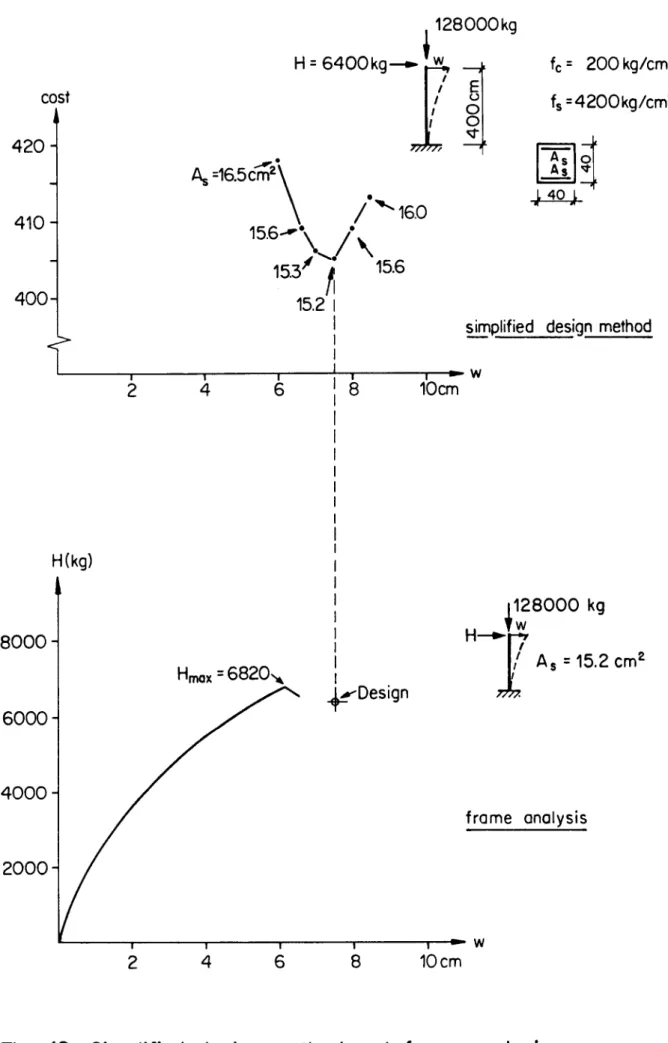
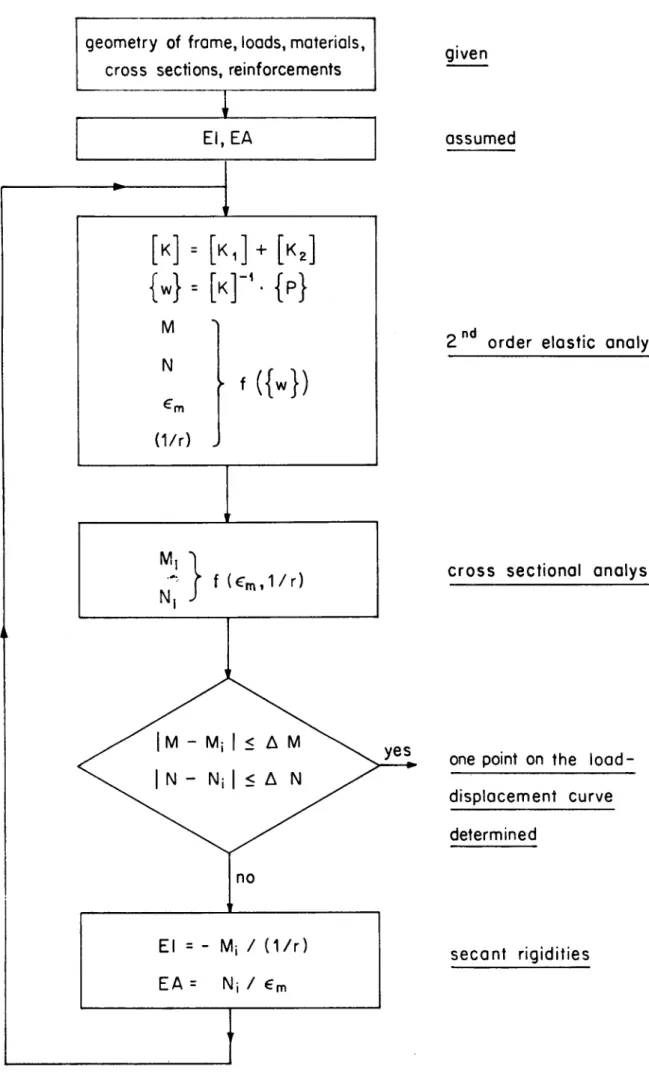
Fig.
4 shows the flow-chart used fordetermining
apoint
on the load-dis¬placement
curve. Theprocedure
starts with assumedrigidities
for all ele¬ments. In a second order elastic
analysis,
the elastic forces M and N, andthe strain distribution
expressed
byJ middle strain e and curvature (Vr) mare determined for all elements. The inelastic forces M. and N. are deter-
l l
mined in a cross sectional
analysis
based on the strain distributions found in the elasticanalysis.
Thus strainequality
isautomatically
satisfied.Force
equality
then becomes the iteration criterium of theprocedure.*
If
equality
is not satisfied,improved
secantrigidities
are determinedfrom the inelastic forces, and the
procedure
isrepeated.
The maximum load
capacity
of slender reinforced concrete frames is asso¬ciated with
instability
as indicated inFig.
5. In load controlled proce¬dure where the external load is increased
step by step,
a poor convergencecan be
expected
near to the maximum load. In adisplacement
controlled pro¬cedure, where a characteristic
displacement
is increasedstep by step,
and thecorresponding
load is calculated, noproblem
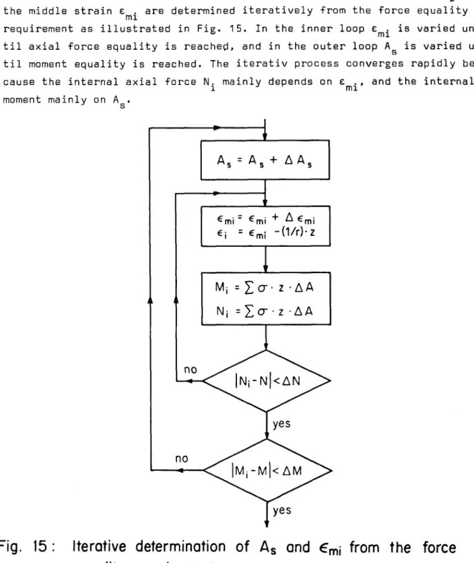
of convergence is encountered.*) A
slight
differentprocedure
was used in the program[14]
in order to ensure convergence. In the cross sectionalanalysis
the middle strain e .mi was determined
iteratively
tosatisfy
the axial forceequilibrium.
The curvature waskept
constant. Moment and middle strainequality
becamethe iteration criteria in this case.
geometry of frame, loads, materials,
cross
sections, reinforcements
EI.EA
[k]
=[k,]+[k2]
M N
(1/r)
> f ({«})
M, N,
f Um,1/r)
no
El
=EA
=M; / (1/r) N-, / em
given
assumed
2
ndorder elastic analysis
cross
sectional analysis
ye^.
onepoint
onthe load-
displacement
curvedetermined
secant
rigidities
Fig. 4: Flow-Chart for frame analysis
21
maximum load capacity, instability failure
material failu're
*-
displacement
Fig. 5: Load-displacement curve for a slender reinforced concrete frame
In the
present study,
external loads on a frame are diveded into constantand
proportional
loads(Fig.
6). The latters areproportional
to a loadfactor X, the^maximum value of which is searched. A
displacement
controlledprocedure
will be used. Thedisplacement
w is increased insteps
until themaximum value of X has been found.
For each value of the
speeified displacement
w, thecorresponding
load fac¬tor X is found
iteratively
as outiined in thefollowing.
Firstrigidities
are assumed for all elements. Then, for the same
rigidities,
the load fac¬tor X is increased in
steps
until calculated andspeeified displacement
eoineide. New
rigidities
can now be determined in the cross sectional ana¬lysis.
Theprocedure
isrepeated
until assumed and calculatedrigidities
agree. The outiined
procedure
wasslightly
modified in the above mentionedprogram in order to
speed
up the convergence (seeFig.
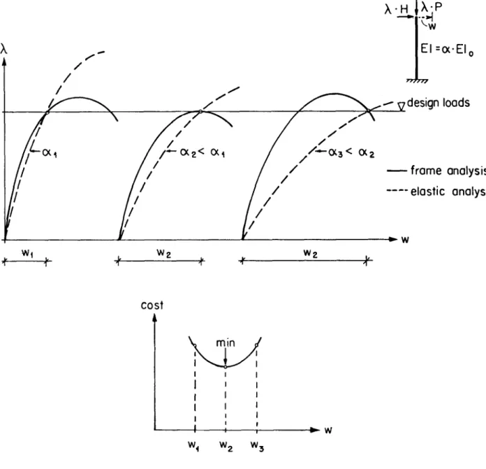
6).Generally,
anon-linear relation exists between the load factor and the
displacements
even if the
rigidities
arekept
constant. The reason is that thegeometri¬
cal stiffness matrix
[K2] (Eq.
2.1)depends
on the axial forces N which, in turn,depend
on the load factor X. However, if the axial forces intro¬duced into the
geometrical
stiffness matrix are assumedindependent
of X,a linear relation between X and the
displacements
results. In this caseit is suffieient to consider two
loading
cases, for instance Xequal
to 1and X
equal
to 2. The load factorcorresponding
to thespeeified displace-
X
k
2-
' \ elastic
1. iteration
last iteration
/ i./ >¦
elasticanalysis, EA,El,N
areassumed
/ /v
constantin each iteration
"/' / X=2
real load-displacement
curveXP
-+-¦
controlled displacement
wFig. 6: Displacement controlled determination of a point on the
real load-displacement curve
ment w is found
by
linearinterpolation
as indicated inFig.
6. For thisnew load factor new
rigidities
and axial forces to be introduced in[K2]
are determined. The
procedure
isrepeated
until the calculatedrigidities
and axial forces agree with the assumed ones.
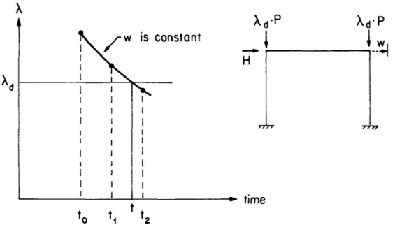
Under sustained loads the
long-time
load factor X, isgiven
(seeFig.
7).The
displacement
w is increased insteps
as before(Fig.
7corresponds
toone value of w. The starting6 time is t ). For each
step
of w, the time iso
increased in
steps.
For eachstep
in time, thecorresponding
load factor Xis determined as before
considering
the creep of concrete. When the cal¬culated load factor X is
equal
to thegiven
load factor X ., the time cor¬responding
to the chosendisplacement
has been found. If the calculated Xat the starting° time t is less than X ,, creep
instability
failure has takeno d
place.
- 23
w
is constant
Xh-p
H
XdP
I-,
time
*0 U f2
Fig. 7: Displacement controlled procedure under sustained loads
3.2 Assumed material
properties
The assumed short-time stress-strain relations* for steel and concrete un¬
der instantaneous
loading
to failure for apreviously
unloadedspecimen
areshown with solid lines in
Fig.
8. Tensile stresses o are takenpositive.
The maximum stress in the short-time stress-strain relation is the
strength
on the
material,
which will be denoted f. Material failure is related to the strain. A failure strain for concrete of -0.0035 is assumed. The stress- strain relations under instantaneousunloading,
and instantaneousreloading
after a time of creep are indicated with dashed lines in
Fig.
8.Creep
under variable stress is calculatedby dividing
the stresshistory
into time intervals, andassuming
a constant stress within each intervalas indicated in
Fig.
9. Two methods, outiined in ref.[24],
are considered.For both methods it is assumed that creep under
varying
stress can be ob¬tained from creep curves for constant stresses. Such curves, for two stress levels o and 0 , are indicated
by
solid lines inFig.
9. The two methodsci c2
differ in the manner data from the creep curves for constant stress is
) The mathematical formulation of the assumed stress-strain-time rela¬
tions is
given
inAppendix
A2.arctan
E,
steel stress-strain relation
1 ?
€i
0.010concrete stress-strain relation
(Tr.
(neg)
rshort-time: ac
=fc[2(ö|fe)
+(äöoz)2] for 0>€t> -0.002
instantaneous loading
nstantaneous unloading
&C3^arctan Ec
*
creep under constant stress
0.002 -0.0035
€t(neg)
Fig. 8: Stress-strain relations
stress history
rateof creep method
<TC
k
°c2-]
ac\-
strain hardening method
t,
-1« -**
-^t
Fig. 9: Creep under variable stress
25 -
transformed to the
varying
stress case.The first method, the "rate of
creep"
method, is based on theassumption
that the creep increase
during
the time interval At =t2
-ti (Fig.
9)under the stress a is
equal
to the creep increase betweenti
andt2
in c2the constant-stress creep curve for the stress a .
Thus,
the creep increase c2is
independent
of theprevious
stresshistory.
The second method called the "strain
hardening" method,
is also based onthe increase of strain in the time interval At taken from the constant- stress creep curve. However, instead of
starting
at the timetj,
the strainincrease is calculated from a fictitious time t_
corresponding
to the timethat would have been necessary to
develop
the totalprior
creep e underc c
the new stress level 0 . This is indicated
by
the horizontal translation c2in
Fig.
9. Hence, the increase of strain in the strainhardening
method de¬pends
on theprevious
stresshistory.
A
comparision
between recorded andpredicted
strainsby
the two methods isshown in
Fig.
10 (taken from Ref.[24]).
Undermonotonically increasing
stress the rate of creep method
underestimates,the
strainhardening
methodoverestimates the increase of creep strain. Thus, the two methods seem to
give
a lower and upper bound for the increase of creep.-2000
^-1600-1
|-12001
u
-800
"
-400 0
-500
-400
o
-300
I -200
o
B -100
strain hardening-v
observed
,VCUV"
^H
—j
rate
of creep
0 8 40 80 120
age in days
Fig. 10: Comparison of recorded strains (from Ref.[25]) with pre
dictions by rate of creep and strain hardening methods.
The figure is taken from Ref. [24]
- 27 -
4. DESIGN METHOD
4.1
Introductory
remarksThe purpose of a
design
method is to determine cross sections and reinforce¬ments for
given design
loads. It isimportant
to note that thedesign
methodoutiined in the
following
can beapplied
to any limit state. Forinstance,
ifdisplacements
underworking
loads govern thedesign,
thedesign
methodcan be used as well. In this case the limited
displacements
introduce addi¬tional restraints.
Basis of the
design
methods are the elasticanalysis,
the cross sectionalanalysis
and the force and strainequality requirements.
The essential ofthe methods concerns the cross sectional
analysis.
In an interative proce¬dure the cross section and reinforcement are
changed
tosatisfy
the forceand strain
equality requirements.
The
design
methods consideronly
thedesign
loads and not theloading path
up to this load level. The stress in any
part
of a structuredepends
on theprior
stress-strain-timehistory
as outiined in Section 3.2, and it isgenerally
necessary to follow thishistory step by step.
Theonly
case wherethis
step by step procedure
issuperfluous,
is short-timeloading
where thestress increases
monotonically
in allparts
of the structure. Thegeneral design
method will be limited to short-timeloading,
and the short-time stress-strain relationsgiven
inFig.
8 will be assumed. For thesimpli¬
fied
design method,
anapproximate
way to account for sustained loads will be outiined.4.2 General
design
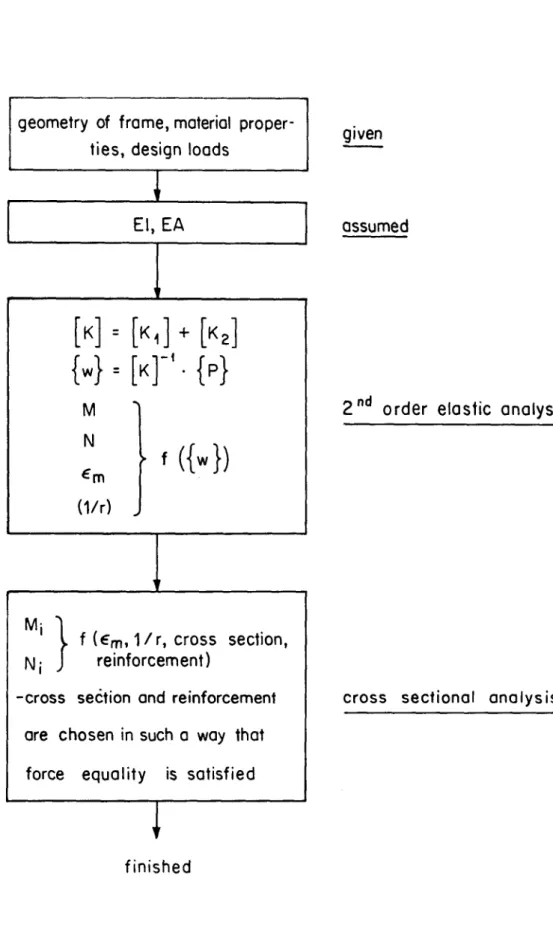
methodThe
general procedure
is outiined inFig.
11 in the form of a flow-chart.Given is a set of
design
loads.Rigidities
of the elements are assumed.Elastic forces and strain distributions are determined in a second order elastic
analysis.
The inelastic forces in the cross sectionalanalysis
are calculated for the strain distributions found in the elasticanalysis.
Thusstrain
equality
is satisfied. The cross section and reinforcement for each section areiteratively changed
until forceequality
is satisfied. Then,according
to Section 2.1, the Situationcorresponds
to apoint
on the realload-displacement
curve of the frame.Two
major
difficulties are encountered in the outiineddesign
method.geometry of frame, material proper¬
ties, design loads
El, EA
[k]= [><<]
+[k2]
{w}.[k]-'.{p}
M N
*m (1/r)
> f ({•})
Mi 1
,y f (€m, 1/r,
crosssection, Nj J reinforcement)
-cross
section
andreinforcement
are
chosen in such
away that force equality is satisfied
T
finished
given
assumed
2
ndorder elastic analysis
cross
sectional analysis
Fig. 11: Flow-chart for general design method
29 -
The first one concerne the choice of
rigidities.
This choice affects themoment
distribution,
the slenderness effect andconsequently
the straindistribution. This
aspect
will be considered further in connection with thedesign
criterionia
Section 4.5.The choice of cross section and reinforcement to
satisfy
the forceequality requirement represents
anotherproblem.
This is illustrated with reference to asimplified
section shown inFig.
12.£
vA
o-2 =
f (e2)
cr1=f(€<)
=»
N
M
Fig. 12 : Determination of cross section
The elastic forces M and N, and the strain distribution
expressed by
themiddle strain e and the curvature Vr have been determined in a second or- m
der elastic
analysis. Equality
between inelastic and elastic forces re¬quires
Ol + 02 • A N
These two
equations together
with the real stress-strain relation for the materialgive
the unknowns, i.e. the area A and thedepth
h. In the caseof an elastic material these can be obtained
explieitly
asA = N/(2*E«e )
m
h = /- 2-n
/(E-A'Vr))'
In the case of non-linear materials such as reinforced concrete, the un¬
knowns are determined

![Fig. 10: Comparison of recorded strains (from Ref.[25]) with pre](https://thumb-eu.123doks.com/thumbv2/1library_info/4425048.1584411/29.874.268.625.144.762/fig-comparison-recorded-strains-ref-pre.webp)