Anisotropic optical properties of Fe/GaAs(001) nanolayers from first principles
Sebastian Putz, Martin Gmitra, and Jaroslav Fabian
Institute for Theoretical Physics, University of Regensburg, D-93040 Regensburg, Germany (Received 28 February 2014; revised manuscript received 13 June 2014; published 31 July 2014) We investigate the anisotropy of the optical properties of thin Fe films on GaAs(001) from first-principles calculations. Both intrinsic and magnetization-induced anisotropy are covered by studying the system in the presence of spin-orbit coupling and external magnetic fields. We use the linearized augmented plane wave method, as implemented in theWIEN2Kdensity functional theory code, to show that theC2vsymmetric anisotropy of the spin-orbit coupling fields at the Fe/GaAs(001) interface manifests itself in the corresponding anisotropy of the optical conductivity and the polar magneto-optical Kerr effect. While their magnetization-induced anisotropy is negligible, the intrinsic anisotropy of the optical properties is significant and reflects the underlyingC2v
symmetry of the Fe/GaAs(001) interface. This suggests that the effects of anisotropic spin-orbit coupling fields in experimentally relevant Fe/GaAs(001) slabs can be studied by purely optical means.
DOI:10.1103/PhysRevB.90.045315 PACS number(s): 31.15.A−,75.70.Tj,78.20.Ls,79.60.Jv
I. INTRODUCTION
Spintronics is an attempt to generalize conventional elec- tronics by exploiting the electron spin as an additional degree of freedom. The goal of semiconductor spintronics [1,2] is to design novel nanoelectronic devices [3–5] that exploit spin ef- fects, and whose fabrication can be seamlessly integrated into the existing infrastructure for complementary metal-oxide- semiconductor (CMOS) technology. Semiconductor spintron- ics rests on three pillars: spin injection, spin manipulation, and spin detection. First, a nonequilibrium spin distribution needs to be created by spin injection from a ferromagnet into a semiconductor. By exploiting spin-orbit coupling (SOC) effects in the material, it can then be manipulated by magnetic or electric fields before the resulting spin distribution is eventually detected.
The Fe/GaAs heterostructure was the first system in which room-temperature spin injection from a ferromagnet into a semiconductor was achieved [6]. It is an ideal model system for spin injection: Iron contributes its high Curie temperature and spin moment, and gallium arsenide its high carrier mobility and its long spin lifetime. Moreover, the lattice mismatch of these materials is rather small [7]. That allows for the epitaxial growth of unstrained Fe/GaAs interfaces, whose preparation is cheap and has been demonstrated repeatedly [8–10].
Although the Fe/GaAs(001) interface quality is known to be limited by various surface reconstructions and possible interdiffusion processes, it is easier to prepare than the Fe/GaAs(110) variant [11,12] and is thus the more widely studied system. The interface structure crucially determines the electronic structure of the system, such as the spin polarization at the Fermi level and the magnetic moments.
It was found that arsenic termination of the Fe/GaAs(001) interface limits diffusion processes and favors a flat interface structure over a partially intermixed one [13–15]. Given the complexity of a quantitative calculation covering two interface structures in the same unit cell, we choose a model system covering only the dominant (flat) inferface structure. Since the symmetry properties of both aforementioned interface structures are equal, we do not expect a qualitative change of the results. Consequently, an As-terminated flat interface
was chosen as the basic structure for the model calculations of the present study.
The microscopic structure of the Fe/GaAs(001) interface exhibits C2v symmetry [2], which manifests itself in many properties of the system. For example, the in-plane mag- netocrystalline anisotropy of thin Fe layers on GaAs(001) has a dominant uniaxial contribution [16–22]. Furthermore, Fe/GaAs(001) shows a small but very robust tunneling anisotropic magnetoresistance effect, which was demonstrated by Moser et al. in 2007 [23]. The tunneling anisotropic magnetothermopower and spin-Seebeck effects are similar phenomena that have been predicted for this system [24,25].
All these anisotropic effects can be directly attributed to the C2v symmetry of the effective SOC magnetic field at the Fe/GaAs(001) interface [26–28], which includes both Bychkov-Rashba [29] and Dresselhaus [30] contributions that stem from the structure inversion asymmetry and the bulk inversion asymmetry of the system, respectively.
In the present paper we investigate the influence of the anisotropic interface SOC fields on the optical properties of the Fe/GaAs(001) heterostructure by means of density functional theory model calculations. While we find the direction of magnetization of the Fe layer to have a negligible effect on the optical properties, the intrinsic (or crystallographic) optical anisotropy is significant. We show that it is manifest in an anisotropic optical conductivity as well as an anisotropic polar magneto-optical Kerr effect (AP-MOKE). The latter means that the Kerr angles (rotation and ellipticity) at normal incidence of the probing beam depend on its direction of linear polarization, thus reflecting the underlying anisotropy of the optical constants of the material. We find the AP-MOKE of our Fe/GaAs(001) model system to have the sameC2vsymmetry as the SOC fields at the interface. The anisotropy that we observe in the optical conductivity of ourC2v structure is to be contrasted with theabsenceof anisotropy in the Boltzmann dc conductivity [31] of a two-dimensional electron gas with Bychkov-Rashba and Dresselhaus spin-orbit interactions.
In the next section we present the methods used to perform the calculations of this study. It is followed by a discussion of the results and concluding thoughts.
II. METHOD
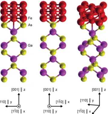
We choose a slab supercell of 15 atoms (see Fig. 1) to model an Fe/GaAs(001) interface consisting of 9 monolayers of GaAs(001) and 3 monolayers of Fe. The interface is As terminated and flat, and the vacuum distance between neighboring slabs is 6 ˚A. The structure is not relaxed, but experimental values for the lattice constants are chosen.
Passivation of the structure with hydrogen is not necessary since an explicit calculation shows that the SOC contribution of the As atoms at the bottom of the structure to the optical properties is negligible.
The linearized augmented plane wave method [32], as im- plemented in the density functional theory (DFT) code package
WIEN2K[33], is used to calculate the electronic structure of the system for various directions of the magnetization in the Fe layer. Here, a Monkhorst-Pack [34] mesh of (12×12×1) k points in the full first Brillouin zone is used, and an accuracy of 10−7Ry in the total energy is chosen as the convergence criterion. We use the Perdew-Burke-Ernzerhof [35] variant of the generalized gradient approximation for the exchange-correlation functional. Spin-orbit coupling is included in all calculations and for all atoms of the supercell using the method of second diagonalization native toWIEN2K. To study the magnetization-induced anisotropy of the system, the calculations are performed for the magnetization M oriented along x, y, and zas well as selected intermediate directions in the xy plane. The mapping of Cartesian to crystallographic axes is given in Fig.1.
On top of the converged electronic densities of the previous step, we calculate the dielectric function and the
FIG. 1. (Color online) The supercell used to model the Fe/GaAs(001) interface viewed from three different angles. The co- ordinate tripods indicate the mapping of Cartesian to crystallographic axes.
optical conductivity in linear response. Here, a much denser Monkhorst-Pack mesh consisting of at least (70×70×1) k points is used. The obtained results are converged for all practical purposes. TheWIEN2Koptics package makes use of the following expression [36] to calculate the imaginary part of the complex dielectric tensor from the converged Kohn-Sham eigensystem:
Im[αβ(ω)]= 2e2 π m2eω2
n=n
dkαnn,kβnn,k
×[f(n,k)−f(n,k)]δ(n,k−n,k−ω), (1) whereαnn,k= n,k|pˆα|n,kis the transition matrix element of theα component of the momentum operator for a direct interband transition (n=n) from the initial Kohn-Sham state |n,k with energy n,k into the final state |n,k with energyn,k. The Fermi-Dirac distribution function evaluated at energy n,k is given by f(n,k), me denotes the electron mass, andωis the angular frequency of the electromagnetic radiation causing the transition.
Thek-space integration uses the Bl¨ochl tetrahedron method [37] and only direct interband transitions from occupied to unoccupied bands up to an energy of 20 eV above the Fermi level are taken into account. An energy resolution of 13.6 meV is chosen for the photon energyω, and a Lorentzian broadening of 100 meV is applied to account for finite-lifetime effects. Since that broadening distorts the results unphysically for energies on the same order, results for energies smaller than 300 meV are not shown.
The real part of the complex dielectric tensor is obtained from the imaginary part by a Kramers-Kronig transformation.
The complex optical conductivity tensor can then be calculated according to [38]
σαβ(ω)= ω
4π i[αβ(ω)−δαβ]. (2) The AP-MOKE rotation and ellipticity angles depend both on the photon energy ωand the polarization state of the probing light beam at normal incidence, which means propagation along the−zdirection and linear polarization in thexyplane. Rotating the direction of linear polarization of the incoming beam about thezaxis by an angleϕis equivalent to rotating the sample by an angle−ϕin thexyplane. We choose the latter description to simplify the derivation of an expression for AP-MOKE. For the present Fe/GaAs(001) model system, withMoriented along z, the complex dielectric tensor is of the form [39–41]
=
⎛
⎜⎝
xx xy 0
−xy xx+δ 0
0 0 zz
⎞
⎟⎠, (3)
whereδ=yy−xxis a measure of the intrinsic anisotropy in thexyplane. TheC2vsymmetry of the system enters through a nonzeroδ, so that the crystallographic structure of the system is reflected in the symmetry of the dielectric tensor. Here and in the following, the explicit dependence of and all derived quantities onωis suppressed to simplify the notation.
A detailed account of the following derivation for a general dielectric tensor can be found in Ref. [42].
Let the incoming beam be linearly polarized along the x direction of the fixed coordinate system. The transformed dielectric tensor for the sample rotated by−ϕabout thezaxis is then given by
=Rz(−ϕ)RzT(−ϕ)=
⎛
⎜⎝
xx xy 0 yx yy 0
0 0 zz
⎞
⎟⎠, (4)
where the superscriptT denotes the transpose. The rotation matrixRz(−ϕ) is defined as
Rz(−ϕ)=
⎛
⎜⎝
cosϕ sinϕ 0
−sinϕ cosϕ 0
0 0 1
⎞
⎟⎠. (5)
The transformed components of the dielectric tensor are expressed as
xx =xx+12[δ−δcos(2ϕ)], (6) yy=xx+12[δ+δcos(2ϕ)], (7) xy =xy+δcosϕsinϕ, (8) yx = −xy+δcosϕsinϕ. (9) We describe the complex electric field vector of polarized light with wave vectorkby the plane wave
E(r,t)=E0exp
i ω
cnr−ωt
, (10) whererandtare the space and time coordinates, respectively, cis the speed of light in vacuum, andn=kc/ωis the vector of complex refractive indices for a wave with wave vector k. In the Jones vector formalism the complex amplitudeE0is described by its transverse components. For propagation along
−zwe can thus write E0 =
E0,x E0,y
. (11)
In general, the polarization state of the reflected beam Er, which has undergone rotation and ellipticity changes, is elliptical. It is determined by the complex reflection matrixρ acting on the incoming beamE0:
Er = Er,x
Er,y
=
ρxx ρxy
ρyx ρyy
E0,x E0,y
. (12) To derive an expression for AP-MOKE, we need to determineρwith respect to the polarization direction rotation angle ϕ. First, we derive the propagation properties of the normal modesEnin the material from the transformed complex dielectric tensorusing the Fresnel equation
+nj⊗nj −n2j1
·En,j =0. (13) Here, 1 is the 3×3 unit matrix, the solution for En,j is the jth normal mode of the material (of which there are in general only two), andnj = |nj|is the absolute value of the
complex refractive index vectornj associated with the normal modeEn,j.
At normal incidence, which means for light propagation along−z, the vector of complex refractive indices takes the formn=(0,0,n)T. This, combined with Eqs. (4) and (13), yields two solutionsnj (j =1,2) with
n2j =xx +yy
2 ±
δ2
4 −xy2, (14) whereas the associated normal modes are described by the parameterβj (j =1,2) given by
βj = En,j,y
En,j,x
= 1 2xy
δ±
δ2−4xy2
. (15) One can then show that the components of the reflection matrixρare given by
ρxx =β2(1−n1)(1+n2)−β1(1+n1)(1−n2) (β2−β1)(1+n1)(1+n2) , (16) ρyy =β2(1+n1)(1−n2)−β1(1−n1)(1+n2)
(β2−β1)(1+n1)(1+n2) , (17) ρyx = 2β1β2(n2−n1)
(β2−β1)(1+n1)(1+n2), (18) ρxy= −2(n2−n1)
(β2−β1)(1+n1)(1+n2). (19) Finally, the total rotationθtotand ellipticityεtotcaused by a material with dielectric tensorcan be written as
θtot= 1 2arctan
−2 Re[ρxxρ¯yx]
|ρxx|2− |ρyx|2
, (20)
εtot= 1 2arcsin
−2 Im[ρxxρ¯yx]
|ρxx|2+ |ρyx|2
, (21) where an overbar indicates complex conjugation. Those quan- tities include contributions from both the diagonal components of, which are even inM, and the off-diagonal components, which are odd inM[43]. Only the latter are of magneto-optical origin and contribute to the pure AP-MOKE, which is why we need to extract their contribution toθtotandεtot. We can expand those quantities as follows:
θtot(M)=θKM+θdiagM2, (22) εtot(M)=εKM+εdiagM2. (23) Here, the indexKindicates a Kerr effect quantity, “diag” refers to the contribution of the diagonal components, andMis the value of the magnetization alongz. The Kerr rotation and the Kerr ellipticity are then given by
θK =12[θtot(M)−θtot(−M)], (24) εK = 12[εtot(M)−εtot(−M)]. (25) The dielectric tensor for the−M case is obtained by per- forming the transformationxy→ −xyin Eq. (3). Combining Eqs. (6)–(8), (14)–(16), (18), (20), (21), (24), and (25), together with the numericalab initioresults for the dielectric tensor
0 45 90 135 180 In-plane rotation [deg]
0 20 40 60 80 100
Total energy difference [μeV]
DFT Fit
FIG. 2. (Color online) Calculated anisotropy ofEtot (solid blue circles) with respect to the angle betweenMin thexyplane and thex axis, relative toEtotmin. The DFT results are fitted with aC2vsymmetric function (dashed brown line).
(3), allows us to determine the energy-dependent AP-MOKE rotation and ellipticity for an incoming beam at normal incidence whose direction of linear polarization in thexyplane is rotated byϕwith respect to thexaxis.
III. RESULTS
In order to study the anisotropy of the model system with respect to the direction of the magnetization M, we calculate the total energy per slab supercell Etot and the real and imaginary part of σxx for M oriented along x, y, and z as well as selected intermediate directions in the xy plane. The total energy Etot exhibits a C2v symmetric anisotropy of about 88 μeV (see Fig. 2), with a minimum of Etotmin= −53 437.348 934 68 Ry for M oriented along x, and a maximum of Etotmax= −53 437.348 928 22 Ry for M oriented along y. In contrast, the anisotropy of the diagonal components ofσwith respect to the orientation ofMis found to be negligible over the whole calculated energy range (not shown). This is attributed to the fact that the magnetization shifts the energy bands of the system mostly ink, but not in the energy. The variation of the Fermi level with the magnetization is therefore very small, and both spin-up and spin-down states are addressed equally by the incoming beam—independent of the direction of magnetization. Note that all subsequent results are obtained forMoriented alongz, and thatσis given in cgs units.
A. Intrinsic anisotropy
In contrast to its negligible magnetization-induced anisotropy, the Fe/GaAs(001) model system exhibits a sig- nificant intrinsic anisotropy. Figure3shows the differing real parts ofσxxandσyy. Both components show pronounced peaks of different height centered at 0.5 eV (σyy) and 0.65 eV (σxx), and an asymptotic decrease to zero for high energies. Theσyy
component shows three intermediate peaks where the relative deviation of the two components is largest. The inset of Fig.3 presents that relative intrinsic anisotropyARexyof the real parts
5 10 15 20
0.3
Photon energy [eV]
0 1 2 3
Re[σ]
[
1015 s-1]
σxx
σyy
5 10 15 20
0.3
Photon energy [eV]
-100 0 100 200 300 400
Relative anisotropy [%]
1 2
3
FIG. 3. (Color online) Real part ofσxx(solid blue line) andσyy
(dashed green line) with respect to the photon energy. The inset shows the relative intrinsic anisotropyARexy (solid red line) with respect to the photon energy. Encircled numbers mark features referred to in the text.
ofσxxandσyycalculated according to ARexy= Re[σyy]−Re[σxx]
Re[σxx] . (26)
WhileARexyis on the order of tens of percent in the visible range of the electromagnetic spectrum, it reaches values above 100%
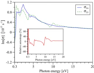
and 400% for 3.8 and 9.6 eV, respectively. Equivalent results for the imaginary part of the optical conductivity are presented in Fig.4. The corresponding relative intrinsic anistropyAImxy, given by
AImxy = Im[σyy]−Im[σxx]
Im[σxx] , (27)
is shown in the inset of Fig.4. It is on the order of tens of percent for the most part of the calculated energy range, with pronounced extrema at energies of 3.7, 9.3, and 10.2 eV. The divergence at 0.6 eV is a consequence of Im[σxx] crossing zero at that energy.
5 10 15 20
0.3
Photon energy [eV]
-1.2 -0.8 -0.4 0 0.4 0.8 1.2
Im[σ] [1015 s-1 ]
σxx
σyy
5 10 15 20
0.3
Photon energy [eV]
-80 -40 0 40 80
Relative anisotropy [%]
FIG. 4. (Color online) Same as Fig.3, but for the imaginary part.
-
πa πa-
πaπa
k
y-0.08 0 0.08
A
Πxy1 (a)
-
πa πa-
πaπa
-0.12 0 0.12
A
Πxy2 (d)
-
πa πa-
πaπa
-0.005 0 0.005
A
Πxy3 (g)
-
πa πa-
πaπa
k
y|s
As ↑(b)
-
πa πa-
πaπa
|p
Asy ↓(e)
-
πa πa-
πaπa
|p
Asx ↓|p
Asy ↓(h)
-
πa πak
x-
πaπa
k
y|p
Asy ↑(c)
-
πa πak
x-
πaπa
|d
Fez2 ↓(f)
-
πa πak
x-
πaπa
|s
Ga ↓|s
As ↓(i)
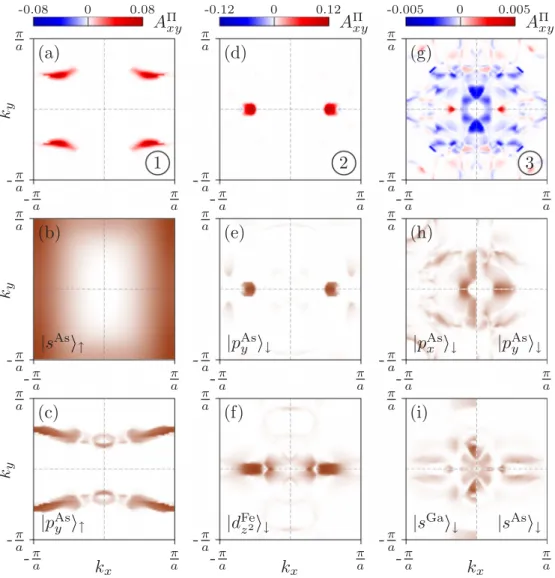
FIG. 5. (Color online) Anisotropy of the transition matrix elements in the first Brillouin zone between the bandsnandncorresponding to the most relevant transitions that contribute to the intrinsic anisotropy of the absorptive part of the dielectric tensor at energies of 9.6, 3.8, and 1.6 eV (first row). Corresponding maps of the spin-resolved orbital atomic partial charge of occupied and unoccupied bands are shown in the second and third row, respectively. The partial charge maps in the third column are split into a positive and a negativekxplane to show the different orbital and atomic characters, clarifying positive and negative valued regions ofAxy.
B. Analysis
Direct interband transitions between two bands n andn can only occur if the matrix elementnn,k is nonzero. For single-photon transitions this means that the wave functions of the optically coupled states are of opposite parity, and that they fulfill the selection rules imposed by the crystal point group and the symmetry of the involved energy bands. For our case of interfacialC2v symmetry and normal light incidence the transition dipole operator transforms under the B1+B2 irreducible representation (note that theC2v symmetry of the system is reduced if the magnetization is not parallel to the zaxis). Transitions between states belonging to the A1 and A2, or theB1andB2, representation are thus forbidden. Also, note that a single-photon transition, which is not allowed at the Brillouin zone centerk=0, can be allowed at finitekbecause of wave function mixing resulting in mixed-parity states. This effect is enhanced in the present case, where the electrons close to the interface experience a potential very different from that in the bulk. Therefore, the bands near the Fermi level comprise
strongly hybridized mixed-orbital states with mixed parity.
By projecting those states to atomic orbitals we can classify them by their irreducible representations and apply selection rules to shed light on the origin of the intrinsic anisotropy of the optical conductivityσ (or, equivalently, the dielectric tensor).
For the real part ofσ, the intrinsic anisotropy at photon energies of about 1.6, 3.8, and 9.6 eV is remarkable (see the labeled features in Fig.3). In order to find the relevant optical transitions at these energies, we identify dominant contributions to the peaks of the real part ofσby calculating the absorptive parts of the dielectric tensorfor each combination of bands n and n. It follows from Eq. (1) that an optical transition contributes to the dielectric tensor if the optical matrix elements and the so called joint density of states are different from zero. In general, there is no simple relation between the conventional total density of states (DOS), the DOS projected on a particular atom (local DOS), the orbital character of the DOS, and the energy dependence of
the absorptive part of the dielectric tensor (ω). The latter incorporates information about all transitions at the photon energyωthat are allowed by the applicable selection rules.
To go one step further, we define thek-resolved anisotropy of the transition matrix elements between initial statenand final statenas
Axy(k)=
ynn,kynn,k−xnn,kxnn,k
δ(n,k−n,k−ω).
(28) The anisotropy Axy(k) allows us to identify regions in the Brillouin zone (BZ) that contribute to(ω). The Dirac delta in the above equation strictly selects the transitions with a photon energy ofω. In order to enhance the visual representation of those regions in Fig.5, we approximate it by a Gaussian with a width of 300 meV. Figure5showsAxy(k) for the three energies 9.6, 3.8 and 1.6 eV, labeled as (1), (2), and (3), respectively.
Note that the intrinsic anisotropy reflects theC2vsymmetry of the system.
The anisotropy at 9.6 eV [label (1) in Figs. 3 and5] is dominated by the transition in the center of the four BZ quadrants [see Fig.5(a)]. Analyzing the k-resolved plots of partial charges [corresponding to the projection of the wave function to the atomic orbitals; see Figs.5(b)and5(c)], we find that the transition from an occupied|s↑ As surface state to an unoccupied|py↑As surface state is dominant for spin-up electrons. Abiding by the optical transition rules for dipolar transitions allowed by the C2v point group, we see that this transition contributes to the absorptive part ofyy. The density of px states at those energies is negligible compared to py, which is why Re[σyy]>Re[σxx]. The deep, localizedpystates on the As surface thus dominate the energy region in which the relative anisotropy reaches values up to 400%.
Significant contributions to the anisotropy Re[σyy]>
Re[σxx] at about 3.8 eV [label (2) in Figs.3 and5] can be assigned to the regions of Axy along the kx line for small ky momenta [see Fig. 5(d)]. Inspecting the partial charges of the involved bands reveals that the transitions responsible for the anisotropy are the spin-down-conserving transitions between an initial|py↓ state of the interface As atoms and a final |dz2↓ state of the Fe atoms above the Ga atoms.
Note that the occupied|py↓ state is partially mixed with a
|dxy↓state. However, the density of the occupied|px↓states and the unoccupied |py↓ states that contribute to Re[σxx] is insignificant for the selected bands, which decreases the anisotropy.
The region where Re[σyy]<Re[σxx] at about 1.6 eV [label (3) in Figs.3and5] is dominated by the transition shown in the right column of Fig.5. We find that the dominant contributions to this transition stem from occupied|py↓and|px↓states of the interfacial As atoms and the unoccupied|s↓ states of the As and Ga atoms underneath. The transition from the|py↓
states give rise to regions of positiveAxy along thekx axis, whereas the regions of negativeAxyalong thekyaxis originate in|px↓initial states.
C. Off-diagonal optical conductivity
Well converged off-diagonal components of the optical conductivity tensor and the dielectric tensor are crucial for
2 4 6 8
0.3
Photon energy [eV]
-0.05 0 0.05 0.1
σxy
[
1015 s-1]
Re Im (a)
0 0.2
X← →Γ
E−EF[eV]
0 0.2
X← →Γ
E−EF[eV]
no SOC
-πa kx πa
-πa
πa
ky
(b)
dx2−y2
dz2
dxy
(c)
n
n−1 dx2−y2
dz2
dxy
(d)
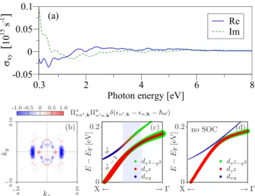
FIG. 6. (Color online) (a) Real (solid blue line) and imaginary part (dashed green line) of the off-diagonal componentσxy of the optical conductivity with respect to the photon energy. (b) Momentum matrix elementsxnn,kynn,kmultiplied by the joint density of states (broadened by 150 meV) for the dominant optical transitions atω= 2.85 eV. (c) Calculated bands along theXline corresponding to the final statesnandn−1. The radii of the circles are proportional to the orbital character of the states in the interfacial Fe layer. Thedx2−y2
anddxy states belong to the Fe atom above the Ga atom, while the dz2character originates from the second Fe atom in the interfacial Fe layer. The region ofkvectors contributing to the spot atkxline in (b) is given in gray. (d) Calculated bands as in (c), but without spin-orbit coupling.
the calculation of magneto-optical quantities such as the Kerr rotationθK or the Kerr ellipticityεK. Figure6(a)shows the result for the off-diagonal componentσxy, which is found to be sufficiently converged at 8100kpoints in the full first Brillouin zone. Note that it is an order of magnitude smaller than the diagonal components.
5 10 15 20
0.3
Photon energy [eV]
-1.2 -0.8 -0.4 0 0.4 0.8 1.2
Kerr rotation [deg]
x-polarized y-polarized
200 400 600 800 1000
Wavelength [nm]
-0.05 0 0.05 0.1
Kerr rotation difference [deg]
FIG. 7. (Color online) Kerr rotation for beams linearly polarized alongx(solid blue line) andy(dashed green line) at normal incidence with respect to the photon energy. The inset shows the absolute difference in Kerr rotation (solid red line) forx- and y-polarized incoming beams with respect to the wavelength.
5 10 15 20 0.3
Photon energy [eV]
-1.6 -1.2 -0.8 -0.4 0 0.4 0.8
Kerr ellipticity [deg]
x-polarized y-polarized
200 400 600 800 1000 Wavelength [nm]
-0.1 0 0.1
Kerr ellipticity difference [deg]
FIG. 8. (Color online) Same as Fig.7, but for the Kerr ellipticity.
Both magnetically ordered states and spin-orbit coupling are necessary to account for magneto-optical effects, which require a nonzeroxy. There are three distinct sources [44]
for nonvanishing off-diagonal components xy: (i) lifting of energy level degeneracies; (ii) hybrid states mixing different spin characters; and (iii) spin-flip transitions due to spin-orbit coupling. For the present Fe/GaAs(001) heterostructure we find that spin-orbit coupling allows the mixing of states of different orbital character that belong to bands of different irreducible representation. This is by far the most important mechanism that translates the effects of the anisotropic spin- orbit coupling fields to the observed anisotropy in the Kerr rotation and ellipticity in the visible range.
In Fig. 6(b) we show a k-resolved plot of xnn,kynn,kδ(n,k−n,k−ω) in the first BZ for the combination of initial (n) and final (n) state that contributes most to Re[xy] at an energy of ω=2.85 eV (435 nm).
This dominant contribution arises from the region close to the center of the X line (ky =0). Inspecting the orbital- and atom-resolved partial charges of the initial state, we find that
FIG. 9. (Color online) Kerr rotation of a probing beam incident along−zwith respect to the photon energy. The azimuth indicates the angle between thexaxis and the direction of linear polarization of the probing beam.
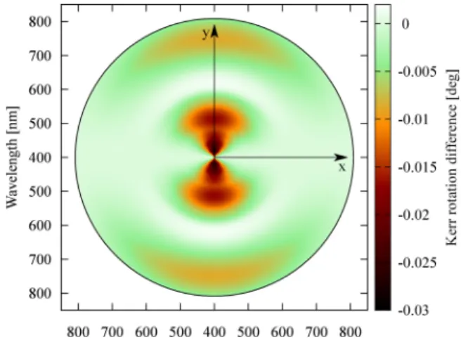
FIG. 10. (Color online) Kerr rotation of a probing beam incident along−z, relative to the Kerr rotation of a probing beam polarized along thexdirection, with respect to the wavelength. The azimuth indicates the angle between thex axis and the direction of linear polarization of the probing beam.
the relevant optical transitions originate in thepx spin-down states of the interfacial As layer. The final staten, however, is a mixed state ofdx2−y2 anddxy character (from the interface Fe atom above the Ga atom), as well asdz2 character [from the second interface Fe atom; see Fig.6(c)]. Note that the final state is also of spin-down character, which means that the transition conserves the spin. Spin-orbit coupling plays a crucial role here because it mixes thedz2 anddx2−y2 states belonging to theA1 irreducible representation of the n−1 band with the dxy character from the A2 representation of band n. This allows a nonzero xnn,kynn,k. Figure 6(d) illustrates that by plotting the two relevant bands without considering spin-orbit coupling.
D. Anisotropic polar MOKE
The AP-MOKE rotation and ellipticity are obtained ac- cording to the procedure described in Sec.II. Figure7shows the Kerr rotations for incoming beams polarized along x andy at normal incidence along −z. Their absolute values are smaller than 1◦ over the whole calculated energy range,
FIG. 11. (Color online) Same as Fig.9, but for the Kerr ellipticity.
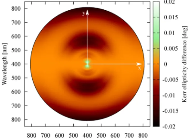
FIG. 12. (Color online) Same as Fig. 10, but for the Kerr ellipticity.
with the largest deviation at an energy of about 10 eV.
The inset shows the absolute difference in Kerr rotation for the x- and y-polarized incoming beams with respect to an experimentally relevant wavelength range. The absolute value of that difference does not exceed 0.1◦in the given wavelength range.
Analogous results for the Kerr ellipticity are presented in Fig. 8. The absolute value of the ellipticity is smaller than 0.5◦ for energies smaller than 8 eV, while it is on the order of 1◦ for higher energies. The largest deviation in Kerr ellipticity for anx- andy-polarized incoming beam occurs at about 9 eV. The inset shows the absolute difference in Kerr ellipticity for thex- andy-polarized case with respect to the wavelength. It is bounded by±0.1◦over the given wavelength range.
The AP-MOKE for arbitrary linear polarization angles of the incoming beam is illustrated by the polar plots in Figs.9–12. The azimuth in those plots corresponds to the angle ϕ(see Sec.II) between the direction of linear polarization of the incoming beam and thex direction, which corresponds to the crystallographic [1¯10] direction (see Fig.1). The photon energy or the wavelength is given along the radial direction, and the color scale indicates the respective magneto-optical quantity.
These plots serve to visualize the C2v symmetry of AP- MOKE (with the two mirror axes alongx andy), which is a manifestation of the underlying effective SOC field symmetry at the Fe/GaAs interface. Depending on its initial polarization state, the reflection of the incoming beam is governed by a transformed dielectric tensor or optical conductivity tensor,
which results in an anisotropy of the calculated magneto- optical quantities.
IV. CONCLUSIONS
We studied the anisotropic optical properties of an Fe/GaAs(001) model system from first-principles calculations.
While the anisotropy of the optical conductivity with respect to the direction of magnetization in the Fe layer is found to be negligible, the intrinsic anisotropy is significant. The relative intrinsic anisotropy of the real and imaginary parts of the optical conductivity in the infrared, visible, and ultraviolet spectrum is on the order of tens of percent, with maxima of up to 100% and 400% at certain energies.
In addition to the optical conductivity, the anisotropic polar magneto-optical Kerr effect was studied for arbi- trary linear polarization directions of the probing beam at normal incidence. The resulting anisotropic Kerr rotation and Kerr ellipticity reach values up to about ±1◦ and reflect the underlying C2v symmetry of the Fe/GaAs(001) interface.
It should be noted that our results are for an ideal, clean, and uncapped model system. Experimental results for real samples are usually influenced by dirt and protective capping layers, which have been shown to reduce the size of the observed effects [45,46]. It is thus very likely that our values for the Kerr angles are larger than they would be in the experiment [47,48].
In the visible range of the electromagnetic spectrum our results are well below 1◦ (about 0.2◦), which is typical for transition metal compounds [49]. While interface imperfections and protective capping layers might lead to quantitatively different experimental results, the qualitative results presented here are expected to be observable in high-quality samples using state-of-the-art optical setups.
In conclusion, our results suggest that the effects of the C2v symmetric effective SOC fields at the Fe/GaAs(001) interface can be studied by purely optical means in ex- perimentally relevant samples. Interfacial effects, including lowering of the planar symmetry along the interface, play an increasingly important role in the electronic transport and the optics of nanostructures. By controlling the interface electrically, for example, one could also control the spin-orbit fields and thus modify the electric and optical properties of the connected electronic system (in our case ferromagnetic iron).
ACKNOWLEDGMENT
This work was supported by GRK 1570 and SFB 689 of the German Research Foundation.
[1] I. ˇZuti´c, J. Fabian, and S. Das Sarma,Rev. Mod. Phys.76,323 (2004).
[2] J. Fabian, A. Matos-Abiague, C. Ertler, P. Stano, and I. ˇZuti´c, Acta Phys. Slovaca57,565(2007).
[3] S. Datta and B. Das,Appl. Phys. Lett.56,665(1990).
[4] B. T. Jonker,Proc. IEEE91,727(2003).
[5] I. ˇZuti´c and H. Dery,Nat. Mater.10,647(2011).
[6] A. T. Hanbicki, B. T. Jonker, G. Itskos, G. Kioseoglou, and A. Petrou,Appl. Phys. Lett.80,1240(2002).
[7] S. A. Chambers, F. Xu, H. W. Chen, I. M. Vitomirov, S. B.
Anderson, and J. H. Weaver,Phys. Rev. B34,6605(1986).
[8] J. R. Waldrop and R. W. Grant,Appl. Phys. Lett.34,630(1979).
[9] J. J. Krebs, B. T. Jonker, and G. A. Prinz,J. Appl. Phys.61, 2596(1987).
[10] G. Wastlbauer and J. A. C. Bland,Adv. Phys.54,137(2005).
[11] C. H. Li, G. Kioseoglou, O. M. J. van ’t Erve, A. T. Hanbicki, B. T. Jonker, R. Mallory, M. Yasar, and A. Petrou,Appl. Phys.
Lett.85,1544(2004).
[12] A. Gr¨unebohm, H. C. Herper, and P. Entel,Phys. Rev. B80, 064417(2009).
[13] T. J. Zega, A. T. Hanbicki, S. C. Erwin, I. ˇZuti´c, G. Kioseoglou, C. H. Li, B. T. Jonker, and R. M. Stroud,Phys. Rev. Lett.96, 196101(2006).
[14] T. Ashraf, C. Gusenbauer, J. Stangl, G. Hesser, M. Wegscheider, and R. Koch,J. Phys.: Condens. Matter23,042001(2011).
[15] L. R. Fleet, K. Yoshida, H. Kobayashi, Y. Kaneko, S. Matsuzaka, Y. Ohno, H. Ohno, S. Honda, J. Inoue, and A. Hirohata,Phys.
Rev. B87,024401(2013).
[16] M. Gester, C. Daboo, R. J. Hicken, S. J. Gray, A. Ercole, and J. A. C. Bland,J. Appl. Phys.80,347(1996).
[17] M. Z¨olfl, M. Brockmann, M. K¨ohler, S. Kreuzer, T. Schweinb¨ock, S. Miethaner, F. Bensch, and G. Bayreuther, J. Magn. Magn. Mater.175,16(1997).
[18] M. Brockmann, M. Z¨olfl, S. Miethaner, and G. Bayreuther, J. Magn. Magn. Mater.198-199,384(1999).
[19] F. Bensch, R. Moosb¨uhler, and G. Bayreuther,J. Appl. Phys.
91,8754(2002).
[20] K. Zakeri, T. Kebe, J. Lindner, and M. Farle,J. Magn. Magn.
Mater.299,L1(2006).
[21] G. Bayreuther, J. Premper, M. Sperl, and D. Sander,Phys. Rev.
B86,054418(2012).
[22] Y. Fan, H. B. Zhao, G. L¨upke, A. T. Hanbicki, C. H. Li, and B. T. Jonker,Phys. Rev. B85,165311(2012).
[23] J. Moser, A. Matos-Abiague, D. Schuh, W. Wegscheider, J. Fabian, and D. Weiss,Phys. Rev. Lett.99,056601(2007).
[24] C. L´opez-Mon´ıs, A. Matos-Abiague, and J. Fabian,Phys. Rev.
B89,054419(2014).
[25] C. L´opez-Mon´ıs, A. Matos-Abiague, and J. Fabian, arXiv:1309.3463.
[26] A. Matos-Abiague and J. Fabian, Phys. Rev. B 79, 155303 (2009).
[27] A. Matos-Abiague, M. Gmitra, and J. Fabian,Phys. Rev. B80, 045312(2009).
[28] M. Gmitra, A. Matos-Abiague, C. Draxl, and J. Fabian,Phys.
Rev. Lett.111,036603(2013).
[29] A. Bychkov and E. I. Rashba, JETP Lett.39, 78 (1984).
[30] G. Dresselhaus,Phys. Rev.100,580(1955).
[31] M. Trushin and J. Schliemann,Phys. Rev. B75,155323(2007).
[32] O. K. Andersen,Phys. Rev. B12,3060(1975).
[33] P. Blaha, K. Schwarz, G. Madsen, D. Kvasnicka, and J. Luitz, WIEN2k, An Augmented Plane Wave Plus Local Orbitals Program for Calculating Crystal Properties(Vienna University of Technology, Austria, 2001).
[34] H. J. Monkhorst and J. D. Pack,Phys. Rev. B13,5188(1976).
[35] J. P. Perdew, K. Burke, and M. Ernzerhof,Phys. Rev. Lett.77, 3865(1996).
[36] C. Ambrosch-Draxl and J. O. Sofo,Comput. Phys. Commun.
175,1(2006).
[37] P. E. Bl¨ochl, O. Jepsen, and O. K. Andersen,Phys. Rev. B49, 16223(1994).
[38] M. Dressel and G. Gr¨uner, Electrodynamics of Solids (Cambridge University Press, Cambridge, UK, 2001).
[39] P. S. Pershan,J. Appl. Phys.38,1482(1967).
[40] P. M. Oppeneer, I. Galanakis, P. James, O. Eriksson, and P. Ravindran,J. Magn. Soc. Jpn.23,21(1999).
[41] J. Schoenes, inMaterials Science and Technology, edited by R. W. Cahn, P. Haasen, and E. J. Kramer (VCH, Weinheim, 1992), Vol. 3a, pp. 147–225.
[42] P. Fumagalli, Ph.D. thesis, Swiss Federal Institute of Technology Zurich, 1990.
[43] P. M. Oppeneer, J. Sticht, T. Maurer, and J. K¨ubler,Z. Phys. B 88,309(1992).
[44] H. Ebert,Rep. Prog. Phys.59,1665(1996).
[45] S. Tacchi, A. Stollo, G. Gubbiotti, G. Carlotti, M. Koˇsuth, and H. Ebert,Surf. Sci.601,4311(2007).
[46] N. Lei, Y. Tian, C. S. Tian, L. H. Zhou, L. F. Yin, G. S. Dong, and X. F. Jin,Thin Solid Films515,7290(2007).
[47] M. Hayashi, T. Katayama, Y. Suzuki, M. Taninaka, A. Thiaville, and W. Geerts,J. Magn. Magn. Mater.126,547(1993).
[48] X. Wang, J. Lian, G. T. Wang, P. Song, P. Li, and S. Gao,J.
Magn. Magn. Mater.323,2711(2011).
[49] P. M. Oppeneer, inHandbook of Magnetic Materials, edited by K. H. J. Buschow (North-Holland, Amsterdam, 2001), Vol. 13, pp. 229–422.