Universit¨ at Regensburg Mathematik
Segmentation of three-dimensional images with parametric active surfaces and
topology changes
Heike Benninghoff and Harald Garcke
Preprint Nr. 10/2015
Segmentation of Three-dimensional Images with Parametric Active Surfaces and Topology Changes
Heike Benninghoff
∗and Harald Garcke
†Abstract
In this paper, we introduce a novel parametric method for segmentation of three-dimensional images. We consider a piecewise constant version of the Mumford-Shah and the Chan-Vese functionals and perform a region-based seg- mentation of 3D image data. An evolution law is derived from energy minimization problems which push the sur- faces to the boundaries of 3D objects in the image. We propose a parametric scheme which describes the evolu- tion of parametric surfaces. An efficient finite element scheme is proposed for a numerical approximation of the evolution equations. Since standard parametric meth- ods cannot handle topology changes automatically, an efficient method is presented to detect, identify and per- form changes in the topology of the surfaces. One main focus of this paper are the algorithmic details to handle topology changes like splitting and merging of surfaces and change of the genus of a surface. Different artificial images are studied to demonstrate the ability to detect the different types of topology changes. Finally, the para- metric method is applied to segmentation of medical 3D images.
Keywords: Image segmentation, three-dimensional images, active surfaces, parametric method, topology changes, Mumford-Shah, Chan-Vese, finite element ap- proximation
1 Introduction
One major challenge in image processing is the au- tonomous detection of objects in images and the seg- mentation of the objects from each other and from their environment.
A very popular approach for image segmentation is the active contour method [20], [17]. In the case of classical two-dimensional images, one or more curves, called con-
∗Deutsches Zentrum f¨ur Luft- und Raumfahrt (DLR), 82234 Weßling, Germany, email: heike.benninghoff@dlr.de.
†Fakult¨at f¨ur Mathematik, Universit¨at Regensburg, 93040 Re- gensburg, Germany, email: harald.garcke@ur.de.
tours, evolve in the two-dimensional image domain and stop locally at edges or region boundaries. The motion is described by evolution equations which aim to minimize a certain energy functional. The energies typically contain length terms to control the smoothness of the contours (internal energies) and terms which push the contours to the desired region boundaries or to edges in the image (external energies).
Two main classes of approaches can be distinguished:
The first class are edge-based methods where regions are identified by their boundaries where the image intensity function rapidly changes [20], [23], [13]. The second class are region-based methods where the regions are charac- terized by the mean gray value or mean color, or by the texture or some other grouping [28], [32], [16], [38].
Region-based active contours methods can also be ap- plied on images with so-called weak edges, i.e. edges with only small changes in the image intensity function [16], and on images which contain regions which are groups of smaller objects [3]. Furthermore, the method is less sensitive to noise. If images with high noise have to be segmented, gradient-based approaches may get trapped at locations where the noise is high and the contours may not detect thereal objects in the image.
In this paper, we study volumetric, i.e. three-dimen- sional, images given by a scalar or vector-valued image function u0 : Ω → R(d), where Ω⊂ R3 is an open and bounded image domain. Real images are often defined on a set ofNx×Ny×Nz voxels (=volume pixels), where u0 is locally constant on each voxel. 3D images may be reconstructed by certain 3D imaging procedures like com- puted tomography (CT) or magnetic resonance imaging (MRI), cf. [39], [34].
3D image segmentation aims at dividing a given im- age in connected regions, representing 3D objects in the image or their environment in the image domain Ω. For 3D image segmentation, the boundaries of the regions or objects have to be detected. These boundaries can be represented by a set of two-dimensional surfaces.
The active contours concept [20] can be extended to the three-dimensional case. For 3D images, we can con- sider time-dependent two-dimensional surfaces (active
surfaces) and evolution laws for the surfaces which at- tract them to region boundaries. In particular, we will study extensions of the Mumford-Shah model [28] and the Chan-Vese model [16] to the three-dimensional case.
The articles [17], [18] belong to the first works, where the active contours model [20] is extended to volumet- ric image data. There, an analytical framework is intro- duced for 3D deformable surfaces. For practical compu- tations however, the authors suggest to replace a given 3D image by a sequence of 2D images and to apply the 2D active contour model on each single image, followed by a 3D reconstruction of the surface.
The geodesic active contours model [13] is a popular edge-based method. An extension of the geodesic active contours model to 3D image segmentation is proposed in [14]. The level set method [29] is used to describe the surface implicitly.
The level set method is also used in [40], where 2D and 3D active contour models are presented and applied on medical images. However, practical results are only shown for 2D images. A detailed literature study on 3D brain cortex segmentation is given in [22]. A review on segmentation of medical X-ray computed tomography and magnetic resonance images is presented in [35].
In [27], a combination of edge-based and region-based segmentation methods is proposed. Both explicit (tri- angulated surfaces) and implicit (level set) methods are implemented. For explicit methods a constant global topology is assumed. For images which require topology changes, only the level set method is applied.
The Chan-Vese model [16] is used for 2D and 3D medi- cal applications in [33] to perform heart segmentation us- ing an iterative version of the Chan-Vese algorithm. The level set method with a finite difference scheme is used to solve the segmentation problem numerically. The level set method is also applied in [1] and [36] for active sur- faces. Applications using 3D medical data (i.a. lung and heart segmentation) are considered. In [24], the level-set method is applied for 3D cell membrane segmentation.
An approach for tracking cells in 4D images (3D data + time) has been developed in [25].
Also some parametric approaches for surface evolution exist in literature: In [11], a program called ”The Surface Evolver” is presented which computes evolving triangu- lated surfaces, where the evolution is driven by energy minimization problems with possible constraints. The program is able to perform topology changes like split- ting if this is instructed by the user.
Another explicit method for evolving surfaces by using triangulated surfaces is proposed in [12]. Techniques are introduced for mesh quality improvement and for topol- ogy changes. Splitting is done by a combination of remov-
ing degenerate elements and a certain mesh separation method based on duplication and separation of nodes.
Surfaces are thus split if they become locally too thin.
Merging is detected by searching for edges which are too close.
Finite element approaches for surface evolutions are pursued in [6]. There, the authors do not consider image segmentation applications, but surface diffusion. Several mesh quality routines like mesh regularization (keeping all angles of simplices at a node of the same size), time step control, refine/coarsening routines and angle width control are proposed.
In this paper, we present a novel parametric approach for 3D image segmentation. We present a scheme for im- age segmentation describing the evolution of parametric surfaces. For the numerical approximation, the smooth surfaces are replaced by triangulated surfaces. We make use of a parametric finite element scheme based on [8].
There, a scheme is proposed for surface diffusion, (in- verse) mean curvature flow and non-linear flows. We use and apply this scheme to image segmentation with mul- tiple phases and regions.
Our method also allows for topology changes which have not been addressed in [8]. We efficiently detect topology changes and perform modifications of the sur- face triangulations. In [10], we considered segmenta- tion of two-dimensional images, and used and extended a method to detect topology changes [26] to handle a vari- ety of topology changes of curves. Topology changes in- volving surfaces are more complex compared to topology changes involving curves. For example, if a curve splits up in two subcurves, the discretization has to be modi- fied only at two points, see [10] for details. If a surface is split up in two subsurfaces, many triangles are located in a small volume. The pure detection of such a splitting is quite simple; the idea of an auxiliary background grid [26]
as used for curves can be extended to topology changes of surfaces. However, the modifications of the surface trian- gulation are not as straight-forward as for curves. In case of splitting, we will delete the involved triangles near the splitting point resulting in two surfaces with intermedi- ate holes. Then, we will close the intermediate holes by creating new triangles. Apart from splitting and merg- ing, further topology changes can occur for surfaces: An increase or decrease of the genus of a surface can also oc- cur, for example when a sphere evolves to a torus or vice versa. In summary, the execution of topology changes is the main additional challenge of 3D image segmentation with parametric surfaces. Therefore, one main focus of this paper is the detection, identification and execution of topology changes.
The remaining part of this paper is structured as fol-
lows. In Section 2, we present a region-based active sur- face model where we extend the Mumford-Shah model [28] and the Chan-Vese model [16] to 3D images. We present an efficient parametric scheme for the evolving surfaces. Also multiple phases can be handled. The main part of this paper is the numerical approximation of our scheme and the handling of topology changes which is de- scribed in Section 3. A finite element scheme is presented, a corresponding linear equation is derived and some com- putational details are given including mesh quality as- pects and time step control. The detection, identifica- tion and execution of topology changes is described in detail including a description how to modify the triangu- lations after a topology change has been detected. In Sec- tion 4, we present results from segmentation of artificial test images and real medical images. We demonstrate the different topology changes which can occur during the evolution of surfaces. A final conclusion is drawn in Section 5.
2 Segmentation of three- dimensional images
2.1 Region-based Active Surfaces
We perform image segmentation by active surfaces, the surface-analogue to active contours [20], [17]. The idea of active surfaces is to let surfaces Γ(t),t∈[0, T], evolve in time such that a certain energy functional is minimized.
From the minimization problem, one can derive an evo- lution law such that the surfaces of Γ(t) are attracted to the region boundaries in the given image.
Let Ω⊂R3be open and bounded. We first consider a scalar image functionu0: Ω→R.
In this paper, we restrict on region-based methods for segmentation of 3D images because of advantages of region-based approaches compared to edge-based ap- proaches (cf. Section 1).
The Mumford-Shah [28] method for 3D images aims at finding a set of two-dimensional surfaces Γ = Γ1∪ . . .∪ΓNC and a piecewise smooth function u : Ω → R with possible discontinuities across Γ approximating the original imageu0. The energy to be minimized is
EMS(u,Γ) =σ|Γ|+ Z
Ω\Γ
k∇uk2dx+λ Z
Ω
(u0−u)2dx, (1) whereσ, λ >0 are weighting parameters and|Γ|denotes the total area of the surfaces belonging to Γ. (For non- smooth surfaces, we identify|Γ|with the two-dimensional Hausdorff measure of Γ⊂R3.)
The first term in (1) penalizes the area of the surfaces, the second term does not allowuto change much in Ω\Γ, and the third term requests thatuis a good approxima- tion ofu0.
We first consider two-phase image segmentation, we consider one closed, orientable surface Γ separating two disjoint regions Ω1 and Ω2 such that Ω = Ω1∪Γ∪Ω2. We assume that Γ is oriented by a unit normal vector field~ν pointing from Ω2to Ω1.
Furthermore, we consider a piecewise constant version of the Mumford-Shah functional: We search for a surface Γ and for an approximation u : Ω → R of u0 which is piecewise constant in each region, i.e. u|Ωk =ck,k= 1,2, such that
E(Γ, c1, c2) =
=σ|Γ|+λ Z
Ω1
(u0−c1)2dx+ Z
Ω2
(u0−c2)2dx
(2) is minimized.
Similarly, the Chan-Vese functional [16] can be ex- tended to 3D images. The energy to be minimized is
E(Γ, c1, c2) =σ|Γ|+µ Z
Ω1
1 dx+λ1
Z
Ω1
(u0−c1)2dx +λ2
Z
Ω2
(u0−c2)2dx, (3) whereσ, λ1, λ2>0,µ≥0 are weighting parameters. For µ= 0 andλ1=λ2=λ, this is the functional (2).
The energy defined in (2) depends on the surface Γ and on the image approximationugiven by the coefficientsc1, c2. For minimizing (2), we perform a two-step approach:
First, we fix the surface Γ and consider variations in the coefficients c1, c2. Using the theory of calculus of variations we obtain the mean of the image function in Ωk forck,k= 1,2:
ck = R
Ωku0dx R
Ωk1 dx. (4)
Then, we fixc1andc2and consider small variations of the surface Γ by smooth surfaces Γ(t)⊂Ω, t∈(−, ), with Γ(0) = Γ. Let Ω1(t) and Ω2(t) be the regions separated by Γ(t). We define
f(~x, c1, c2, t) :=
(u0(~x)−c1)2, if ~x∈Ω1(t), (u0(~x)−c2)2, if ~x∈Ω2(t), (5) which is defined for a.e. ~x∈Ω.
By using a transport theorem, we obtain d
dt t=0
E(Γ(t), c1, c2) =
= d dt t=0
σ Z
Γ(t)
1 dA+λ Z
Ω
f(~x, c1, c2, t) dx
!
=−σ Z
Γ
κ VndA+
−λ Z
Γ
(u0−c1)2−(u0−c2)2 VndA
=− Z
Γ
(σκ+F)VndA
where dAis the area element,Vn is the normal velocity, κthe mean curvature andF is an external force given by
F(~x) =λ (u0(~x)−c1)2−(u0(~x)−c2)2
, ~x∈Γ. (6) The fastest decrease of the energy is obtained for
Vn=σκ+F. (7)
Also multichannel images with a vector-valued image function ~u0 : Ω → Rd can be handled. This involves vector-valued coefficients~ck,k= 1,2, and a modification of the external force to, for example,
F(~x) =
d
X
i=1
λi
((u0)i(~x)−(c1)i)2−((u0)i(~x)−(c2)i)2 ,
(8) where the subscript i denotes the i-th component of a vector,i= 1, . . . , d. For computation of the coefficients, each component of~ck is set to the mean of the corre- sponding component of~u0 in the region Ωk,k= 1,2.
In principle, also spaces like the HSV (hue, satura- tion, value) or CB (chromaticity, brightness) space can be used [4], [15], [37]. In these cases, the image function has values on certain submanifolds of Rd. In [10], we proposed a method to segment 2D images using the color space HSV and CB. The method can be transferred also to the 3D case. In many practical applications however, for example medical 3D image data generated by com- puted tomography (CT) or magnetic resonance imaging (MRT), the image function is often scalar-valued (cf. for example the lung image database of The Cancer Imaging Archive (TCIA) [31], [2], [30]).
2.2 Parametric and Multiphase Formu- lation
Equation (7) can be rewritten using a parametric ap- proach to describe the time-dependent surfaces. Fur- ther, we now consider a more general setup of multiple
surfaces Γi(t), t ∈ [0, T], i = 1, . . . , NS, which separate three-dimensional regions Ωk(t),k = 1, . . . , NR. We as- sume that the surfaces are compact and oriented by unit normal vector fields ~νi(. , t) pointing from Ωk−(i)(t) to Ωk+(i)(t), wherek±(i)∈ {1, . . . , NR}.
Let ~xi(. , t) : Υi → R3, i = 1, . . . , NS, be a smooth parameterization of Γi(t), where Υiis a two-dimensional reference manifold, for example the sphere Υi = S2 ⊂ R3. The normal velocity of Γi(t) can be expressed as (Vn)i = (~xi)t. ~νi.
An approximation of the image intensity function u0 is given by the piecewise constant function u(. , t) = PNR
k=1ck(t)χΩk(t), whereχΩk(t)is the characteristic func- tion of Ωk(t) andck(t) is the mean ofu0 in Ωk(t).
For each surface, we define the external forcing term Fi(. , t) =λ (u0−ck+(i)(t))2−(u0−ck−(i)(t))2
(9) and obtain the following scheme for the surfaces: Find
~
xi(. , t) : Υi →R3 and κi(. , t) : Υi →R, i= 1, . . . , NS, satisfying
(~xi)t. ~νi=σκi+Fi, (10a)
∆Γ~xi=κi~νi. (10b) Equation (10a) is a parametric formulation of (7) for mul- tiple regions. Equation (10b) relates the parametrization
~
xi and the curvature κi, see e.g. [19]. The symbol ∆Γ
denotes the Laplace-Beltrami operator. Here, we use a small abuse of notation, i.e. we consider κi and ~νi as functions defined on Υi, i.e. we identify κi withκi◦~xi
and~νi with~νi◦~xi,i= 1, . . . , NS.
3 Numerical approximation
3.1 Finite Element Approximation
We introduce a finite element approximation for the scheme (10) which is based on a scheme developed in [8], where geometric flows of two-dimensional surfaces are considered. We extend the ideas to solve schemes like (10) which arise in image segmentation applications.
Let 0 =t0< t1< . . . < tM =T be a decomposition of the time interval into possibly variable time stepsτm= tm+1−tm form= 0, . . . , M−1.
LetNS denote the number of surfaces and NRdenote the number of regions. Let the smooth surface Γi(tm), i= 1, . . . , NS, be approximated by a polyhedral surface Γmi of the form
Γmi =
Ni,F
[
j=1
σi,jm, (11)
where σi,jm, j = 1, . . . , Ni,F, are disjoint, open simplices (also called faces) with vertices~qmi,j,j= 1, . . . , Ni,V. Fur- ther, let h := maxi=1,...,NS,j=1,...,Ni,Fdiam(σi,jm) be the maximum diameter of a simplex of the triangulated sur- faces. The diameter diam(σi,jm) is defined as the maxi- mum distance between two points ofσmi,j.
Let X~im be a parameterization of Γmi and let Ωmk, k = 1, . . . , NR, denote the open, disjoint subsets of Ω separated by Γmi ,i= 1, . . . , NS. Thus, Ωmk is an approx- imation of Ωk(tm) fork= 1, . . . , NR.
The new surfaces Γm+1i are parameterized over Γmi . Therefore, we define the following finite element spaces
W(Γm) :={(η1, . . . , ηNS)∈C(Γm1,R)×. . .× C(ΓmNS,R) :ηi|σmi,j is linear,
∀i= 1, . . . , NS, j= 1, . . . , Ni,F}, (12a) V(Γm) :=
(~η1, . . . , ~ηNS)∈C(Γm1 ,R3)×. . .× C(ΓmN
S,R3) :~ηi|σm
i,j is linear,
∀i= 1, . . . , NS, j= 1, . . . , Ni,F}. (12b) The spacesW(Γm) and V(Γm) thus consist of scalar or vector-valued, piecewise linear functions defined on Γm.
A basis of W(Γm) is given by functions χmi,j :=
((χmi,j)1, . . . ,(χmi,j)NS)∈W(Γm), where
(χmi,j)k(~qk,lm) =δikδjl (13) fori, k= 1, . . . , NS,j= 1, . . . , Ni,V,l= 1, . . . , Nk,V.
Note, that depending whether the domain of definition is Γm−1or Γm, we can interpret X~m as a different func- tion. In particular we have form≥1, X~m∈V(Γm−1), and form≥0, X~m ∈V(Γm) is the identity defined on Γm.
For scalar functions u = (u1, . . . , uNS), v = (v1, . . . , vNS) ∈ L2(Γm1 ,R)×. . . ×L2(ΓmNS,R) and for vector- valued functionsu= (u1, . . . , uNS),v= (v1, . . . , vNS)∈ L2(Γm1,R3)×. . .×L2(ΓmN
S,R3), we introduce the L2- inner product over the current polyhedral surface Γm as follows:
hu, vim:=
Z
Γm
u . vdA=
NS
X
i=1
Z
Γmi
ui. vidA. (14)
If u, v are piecewise continuous with possible jumps across the edges ofσmi,j, i = 1, . . . , NS, j = 1, . . . , Ni,F, the mass lumped inner product is defined as
hu, vihm:= 1 3
NS
X
i=1 Ni,F
X
j=1
|σi,jm|
3
X
l=1
(u . v)((~qi,jm
l)−), (15)
where ~qi,jm
l, l = 1,2,3, are the vertices of σi,jm, |σmi,j| =
1 2k(~qi,jm
2 −~qmi,j
1)×(~qi,jm
3 −~qi,jm
1)k is the area of σmi,j and u((~qmi,j
l)−) := lim~p→~qm
i,jl, ~p∈σi,jmu(~p).
We assume that the vertices
~ qi,jml 3
l=1, j = 1, . . . , Ni,F, are ordered such that the unit normal~νimat Γmi is given by
~ νmi |σm
i,j :=~νi,jm := (~qi,jm
2−~qi,jm
1)×(~qi,jm
3−~qi,jm
1) k(~qi,jm
2−~qi,jm
1)×(~qi,jm
3−~qi,jm
1)k (16) points from Ωmk−(i) to Ωmk+(i).
We propose the following finite element scheme ap- proximating the scheme (10): Let Γ0be a union of poly- hedral surfaces approximating Γ(0) and letX~0∈V(Γ0) be the identity function on Γ0. FindX~m+1∈V(Γm) and κm+1∈W(Γm),m= 0,1, . . . , M−1, such that
hX~m+1−X~m τm
, χ ~νmihm−σhκm+1, χihm=hFm, χihm,
∀χ∈W(Γm), (17a)
hκm+1~νm, ~ηihm+h∇sX~m+1,∇s~ηim= 0,
∀~η ∈V(Γm). (17b) Here,Fm= (F1m, . . . , FNm
S) is defined by Fim(~qi,jm) :=λ
(u0(X~im(~qi,jm))−cmk+(i))2+
−(u0(X~im(~qi,jm))−cmk−(i))2 ,
for i = 1, . . . , NS and j = 1, . . . , Ni,V and cmk is set to the mean ofu0 in Ωmk fork= 1, . . . , NR.
We further introduce a weighted normal defined at the nodesX~im(~qi,jm) =~qmi,j∈Γmi by setting
~
ωim(~qmi,j) :=~ωi,jm := 1
|Λmi,j| X
σmi,l∈Ti,jm
|σmi,l|~νi,lm, (18)
where for i = 1, . . . , NS and j = 1, . . . , Ni,V, Ti,jm :=
n
σi,lm : ~qmi,j∈σmi,lo
and Λmi,j:=S
σmi,l∈Ti,jmσi,lm.
Further, we set ~vmi (~qi,jm) := ~vi,jm := ~ωmi,j/k~ωi,jmk and
~
ωm= (~ω1m, . . . , ~ωmN
S) and~vm= (~v1m, . . . , ~vmN
S).
As in [7], [8], we make a very mild assumption on the triangulations:
(A) For m = 0, . . . , M, we assume that |σmi,j| > 0 for all i= 1, . . . , NS and j = 1, . . . , Ni,F and for m = 0, . . . , M−1, we assume that dim span
~ ωi,jm Ni,V
j=1 = 3.
The assumption (A) is only violated in very rare cases.
For closed surfaces without self intersections, it always holds.
Theorem 1. Let the assumption (A)hold. Then there exists a unique solution n
X~m+1, κm+1o
∈ V(Γm)× W(Γm)to the system (17).
Proof. (See also [8].) Since the system is linear, it is sufficient to show uniqueness. Therefore, we consider the following scheme: FindX~ ∈V(Γm) andκ∈W(Γm) such that
− 1
τmhX, χ ~~ νmihm+σhκ, χihm= 0, ∀χ∈W(Γm), (19a) hκ ~νm, ~ηihm+h∇sX,~ ∇s~ηim= 0, ∀~η∈V(Γm), (19b) holds. Testing (19a) withχ=κand (19b) with ~η =X~ leads to
στmhκ, κihm+h∇sX,~ ∇sX~im= 0. (20) It follows that κi,j = 0 and X~i,j = C~i ∈ R3 for i = 1, . . . , NS, j = 1, . . . , Ni,V. Inserting κ = 0 and X~ = C~ = (C~1, . . . , ~CNS) in (19a) results in
hC, χ ~~ νmihm= 0, ∀χ∈W(Γm). (21) Choosing χ =χmi,j (the standard basis) and using (18), the definition of~ωi,jm, results in
C~i. ~ωmi,j= 0, ∀i= 1, . . . , NS, j = 1, . . . , Ni,V. (22) Finally, using the assumption (A), it follows thatC~i= 0 for eachi= 1, . . . , NS.
3.2 Solution of the Discrete System
We defineδ ~Xm+1:=X~m+1−X~m. Asδ ~Xm+1andκm+1 are uniquely given by their values at the nodes~qmi,j, we consider them as elements in (R3)N andRN, respectively, whereN=PNS
i=1Ni,V. We introduce the matricesMm∈ RN×N,N~m∈(R3)N×N andA~m∈(R3×3)N×N by
Mm:=
Mm1 · · · 0 ... . .. ... 0 . . . MmNS
,
N~m:=
N~m1 · · · 0 ... . .. ... 0 . . . N~mNS
,
A~m:=
A~1m · · · 0 ... . .. ... 0 . . . A~NmS
,
where Mmi ∈ RNi,V×Ni,V, N~mi ∈ (R3)Ni,V×Ni,V, A~im ∈ (R3×3)Ni,V×Ni,V,i= 1, . . . , NS. Their entries are defined by
[Mmi ]kl:=hχmi,k, χmi,lihm,
[N~mi ]kl:=hχmi,k, χmi,l~νmihm, (23) [A~im]kl:=h∇sχmi,k,∇sχmi,limId~3,
withi= 1, . . . , NS, k, l= 1, . . . , Ni,V. Here,Id~3denotes the identity matrix inR3×3. Further, we introducebm= (b1m, . . . , bNmS)∈RN defined by
[bim]k :=hFim, χmi,kihm, i= 1, . . . , NS, k= 1, . . . , Ni,V. (24) The scheme (17) can be rewritten to the following prob- lem: Let Γ0 be a polyhedral approximation of Γ(0) and let X~0 = (X~10, . . . , ~XN0S) ∈ (R3)N with X~i0 = (X~i,10 , . . . , ~Xi,N0
i,V) such thatX~i,j0 are the coordinates of the vertices of Γ0i fori= 1, . . . , NS,j= 1, . . . , Ni,V. For m= 0, . . . , M−1 findδ ~Xm+1 ∈(R3)N and κm+1∈RN such that
στmMm −N~mT N~m A~m
κm+1 δ ~Xm+1
=
−τmbm
−A~mX~m
.
(25) Applying a Schur complement approach, we can trans- form this system to
κm+1= 1 σMm−1
1 τm
N~mTδ ~Xm+1−bm
, (26a)
1 στm
N~mMm−1N~mT +A~m
δ ~Xm+1=
=−A~mX~m+1 σ
N~mMm−1bm. (26b) Since the system matrix in (26b) is symmetric and pos- itive definite under the assumption (A), there exists a unique solution.
The linear system (26b) can be solved with an itera- tive solver, for example, with the method of conjugate gradients with possible preconditioning, or with a di- rect solver for sparse matrices. For the experiments and examples presented in Section 4 of this paper, we use a MATLAB built-in routine, a direct solver for sparse systems. Even for two-dimensional problems, which re- sult from the evolution of two-dimensional surfaces, the sparse direct solver is very efficient from a computational view.
3.3 Topology Changes
Parametric methods cannot handle topology changes au- tomatically in contrast to other numerical methods like the level set method. During the evolution of surfaces singularities can occur like a pinch-off, see [6], [8]. In or- der to proceed after a pinch-off, the surface has to be split in two single surfaces. Other possible topology changes, that we will consider here, are merging of two surfaces and change of the genus (occurs for example during an evolution of a torus to a sphere or vice versa).
In [26], an algorithm is proposed to efficiently detect splitting and merging of evolving curves inR2, see also [5]. In [10], we used and extended this algorithm to detect topology changes in 2D images. In this paper, we want to adapt this approach to the 3D case. We aim at detecting topology changes which could occur during the evolution of surfaces. Having found the location where a topology change occurs, we propose a method how to modify the triangulations.
3.3.1 Detection of a Topology Change
In [26], a virtual, auxiliary 2D background grid is con- structed which covers a two-dimensional domain, and topology changes of curves are detected if node points from different curves or different parts of one curve are located in one array of the background grid.
Motivated by this method for evolving curves, we pro- pose the following method to detect topology changes of evolving surfaces. The basic idea is the use of a uniform 3D grid of cubes. A topology change may occur, if a large number of nodes or if nodes of different surfaces or dif- ferent parts of one surface (with opposite normal vector) are located in one cube.
In detail, to detect a change in topology, we construct a uniform 3D background grid which covers the image domain Ω. In the following, we assume that Ω is a cuboid.
If the 3D imageu0 is not given on a cuboid volume, we consider a cuboid which contains Ω.
Let Ω = [xmin, xmax]×[ymin, ymax]×[zmin, zmax]⊂R3 be the image domain containing in particular the surfaces Γmi , i = 1, . . . , NS. We consider a grid dividing Ω in a set of many small cubes of edge width a ∈ R. Let the grid consist of Nx×Ny ×Nz cubes, where Nx = ceil((xmax −xmin)/a), Ny = ceil((ymax−ymin)/a) and Nz= ceil((zmax−zmin)/a).
We now perform one loop over all surfaces and nodes X~i,jm,i= 1, . . . , NS,j= 1, . . . , Ni,V. If a nodeX~i,jm is the first node which is detected to lie in a certain cube, we create a new list for that cube, where we store the index pair (i, j). If another node has already been identified to
be located inside that cube, we add the index pair (i, j) to the existing list.
If there is a large number of nodes located in a cube, i.e. more than Ndetect nodes, a topology change likely occurs, and the cube is stored in a list for possible topol- ogy changes. It is also possible that the node density is only locally very high at this location, but no topology change happens.
If there are less thanNdetect nodes in the current list, we compare the surface index and the direction of the weighted normal vector of the current node with those of the nodes already stored in the list. If two different sur- face indicesi1andi2 occur or if two nodes with (nearly) opposite weighted normal vector are located in one cube, a topology change likely happens. The corresponding cube is accordingly stored in a list for topology changes.
After having considered all nodes, the cubes marked for topology changes are considered one by one. If a topology change is identified, the surface triangulation is accordingly changed. Thus, by successively considering all marked cubes, more than one topology change can be executed in one time step. The list can be optionally sorted such that the cube with the largest number of nodes is considered first.
The detection of topology changes is very efficient from a computational view. The effort is of orderO(N), where N is the total number of node points. For comparison, a simple approach, where all possible pairs of two nodes are considered and where the distance between two nodes is computed to detect a topology change, would result in a computational effort of orderO(N2).
Similar as described in [10], the grid size a can be adaptively set, for example dependent on the speed of the evolving surfaces. Therefore the method to detect topology changes is both efficient and robust.
3.3.2 Identification of the Topology Change For identifying which kind of topology change occurs, the nodes of the affected cube, i.e. the current cube of the sorted list, and the nodes of up to 26 neighbor cubes (in total up to 27 cubes, i.e. 3×3×3 cubes) are considered.
LetS ={j1, . . . , jnc} denote the index set of the nodes and letX~j, j ∈ S, denote the coordinates of the nodes located in the cubes. Further, let~ωj,j ∈S, denote the corresponding weighted normal vectors atX~j, recall their definition in (18). For the ease of illustration, we omit the time dependency (time indexm) in the notation.
The different topology changes are distinguished by considering the weighted normal vectors~ωj. The idea is that in case of merging and in case of increasing genus, their are two main group of nodes which can be found
by considering their normal vectors. For splitting and decrease of genus, there are more than two main direc- tions.
The node with indexj =j1 is set as representative of the first group. We choose thresholds thr1 < thr2, for examplethr1 = 20◦,thr2 = 160◦. Forj =j2, . . . , jnc we consider the angleα between ~ωj1 and ~ωj. If α < thr1, the nodej belongs to the first group. If α > thr2 and if the second group is empty, the node j becomes the representative node of the second group. If the second group is not empty, we consider the angleβ between~ωj
and~ωk0, wherek0∈ {j2, . . . , jnc}is the representative of the second group. Ifβ < thr1,j is added to the second group.
For the next search we replace ~ωj1 and ~ωk0 by the average normal vectors~n1 and~n2 of group 1 and group 2, respectively, and re-consider the nodes which could not have been assigned to one group in the first step. If the angle between ~ωj and ~n1 or ~ωj and ~n2 is smaller than thr1, the nodeX~j is added to the corresponding group.
If group 2 is empty, or if one of the groups consists of only a small number of nodes (e.g. <5% of nc), we start again by using another node as representative for the first group (e.g. j = j2), since the node j = j1
could be an outlier. If no start node can be found, such that there exist two groups of nodes as described above, no topology change takes place. This can happen, if all weighted normals point in nearly the same direction.
The method such provides that a topology change like splitting is not wrongly detected at locations where sev- eral nodes are just close to each other but their nor- mal vectors point in the same direction. From a mesh quality point of view, such meshes should be avoided;
the nodes should be distributed equally over the surface.
However, the detection of topology changes should be ro- bust enough not to wrongly detect a splitting at locations where there is just a high density of nodes.
If both groups have a sufficient number of nodes, we proceed by considering the remaining normal vectors which could have not been assigned to one of the two groups. We again consider the angle between ~ωj and
~n1 and ~ωj and ~n2. If both angles are > thr3 (e.g.
thr3 = 40◦), the normal ~ωj points in a complete dif- ferent direction compared to~n1 and~n2. Let N0 be the number of such points. IfN0 exceed a predefined num- ber (e.g. 1/3nc), then there are more than two main groups of directions. In this case, there is a splitting or decrease of genus. Splitting and decrease of genus are handled similarly (see below for details how to modify the triangulations). Triangles close to the detected cube are deleted. If the remaining triangulation of the former surface consists of two connected components, a split-
ting occurs. If the remaining triangulation is connected, a decrease of genus occurs.
If N0 is zero or if it does not exceed the predefined number, possible remaining normal vectors are only sin- gle outliers and there are only two main groups of nor- mal vectors with nearly opposed normal vector. In this case, there is a merging or increase of genus. If there are nodes belonging to two different surfaces, a merging occurs. Otherwise, an increase of genus occurs.
An illustration of the algorithm to detect and identify topology changes is given in Figure 1.
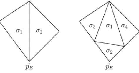
3.3.3 Algorithm for Splitting and Decreasing of Genus
We propose the following algorithm for a possible mod- ification of the surface triangulation after the detection of a splitting or decrease of genus.
• Preparation and deletion of simplices: In case of splitting or decreasing genus, we consider the set of affected nodes X~j, j ∈ S, which are located in the cube or in a neighbor cube, where the topology change has been detected. Let~pEbe the mean of the points{X~j : j∈S}. We delete all simplices with at least one vertex belonging to the set{X~j : j ∈S}.
When deleting one simplex, we change the neigh- bor information of neighbor simplices at the corre- sponding edges to −1 (free edges). Deletion cre- ates two temporary holes in the surface(s). Sim- plices with two or three free edges are deleted as well, see Figure 2. As a result we either have two sets of connected simplices (→splitting) or one set of connected simplices (→decrease of genus).
• Set surface index (splitting only): The remain- ing simplices form two connected sets. For one set, we need to re-set the surface index. Let i be the surface index of the original surface. By splitting the total number of surfaces is increased toNS+ 1.
Starting with one simplex with a free edge, we re-set its surface index from i to NS + 1. Then, we con- sider its neighbor simplices and assign them to sur- faceNS+ 1 also. By this procedure, the simplices of one of the two connected components are assigned one by one to the surfaceNS+ 1 by heritage, i.e. by use of neighbor information.
• Generate new simplices: We close each of the two intermediate holes (where simplices have been deleted) by constructing new simplices at edges of simplices where the neighbor information has been set to−1. First we create two new points, each with
Detection of possible topology change
Identification of topology change Create empty 3D background grid of
grid sizeaand consideri= 1,j= 1.
Consider cube in which (i, j) lies, store indices (i, j)
in a list for that cube.
No. of stored nodes
> Ndetect, or different surface indices or normal vector
directions?
Store cube in a list for possible topology changes.
Last surface and last node?
Sort cubes marked for possible topology changes by the number
of nodes located in the cubes.
Go to next node/surface.
yes
no
yes
no
Consider first cube of the sorted list.
Consider nodes located in current cube and in its 26 neighbor cubes, and their weighted normals~ωj,j∈S.
Consider direction of~ωj, j∈S, and assign nodes to
groups of similar direction.
No. of different groups?
Splitting or de- crease of genus
Merging or in- crease of genus
No topology change
2 remaining connected
surfaces?
Splitting Decrease of genus
2 different surface indices?
Merging Increase of genus
Last cube?
Stop.
Consider next cube of the list.
≥3
= 2
≤1
yes no yes no
yes no
Figure 1: Illustration of the detection and identification of topology changes of surfaces.
Figure 2: Left: Part of the surface near a temporary hole.
Free edges are drawn with red color. Right: Surface near the hole after deletion of simplices with more than one free edge.
σ1 σ2
~ pE
σ1
σ2 σ3 σ4
~ pE
Figure 3: Improving mesh quality after a splitting or decrease of genus - Decrease the number of edges at the node~pE.
coordinates ~pE, one for each intermediate hole. In the next time steps the two nodes can move away from each other. If σ is a simplex with a free edge given byX~σ,j1andX~σ,j2with no neighbor simplex, a new simplex is generated given by the verticesX~σ,j1, X~σ,j2 and one of the two new nodes at~pE. The new simplex inherits the surface index from σ.
• Improve mesh quality: By simply connecting all free edges with one of the two new vertices at ~pE, the two vertices can belong to a big number of sim- plices. Letσ1andσ2be two of the newly generated simplices with one common edge. We construct 4 new simplices from σ1 and σ2 such that the new vertex belongs to only one of the 4 new simplices, see Figure 3. Therefore the number of elements to which the vertices at~pE belong to is approximately halved. We repeat this procedure until each of the newly created nodes atp~E belongs to≤8 elements.
3.3.4 Algorithm for Merging and Increasing of Genus
We propose the following algorithm for a possible mod- ification of the surface triangulation after the detection of a merging or increase of genus.
• Preparation and deletion of simplices: In case of merging or increasing genus, we consider the set of affected nodes X~j, j ∈ S, which are located in the cube or in a neighbor cube, where the topol- ogy change has been detected. We delete all sim- plices with at least one vertex belonging to the set {X~j : j ∈S}. This generates temporary free edges, i.e. simplices exist which do not have a neighbor sim- plex at that edge. The neighbor index corresponding to the free edge is set to −1. This creates two in- termediate holes. Simplices with two or three free edges are deleted as well, see Figure 2.
• Matching free nodes/edges:There exist now two sets of connected free edges. LetIf ree,k,k= 1,2, be the set of nodes corresponding to the free edges (end points of the edges). We try to match the nodes of If ree,1with the nodes ofIf ree,2using the Hungarian method [21] which is a combinatorial optimization algorithm. The Euclidean distance is used as cost criterion for matching two nodes. Since the number of nodes of the two sets need not be equal, there can be nodes which could not have been matched in the first step, see Figure 4 (top). Therefore, new nodes are created by bisection of simplices at a free edge. Finally, each node can be matched, see Fig- ure 4 (bottom).
• Point/Edge merging: Since two matched nodes can have slightly different coordinates, they are re- placed by one node in the middle of the line con- necting the two nodes. The free edges of the two open holes are merged by identifying the matched nodes. The simplices, nodes and edges administra- tion needs to be adapted. The nodes in If ree,1 are updated; each point is replaced by the mid point between it and its matching partner. The nodes be- longing toIf ree,2are deleted. Half of the free edges are deleted. The edge, node and neighbor informa- tion of the simplices at the former holes need to be adapted. In case of merging, the surface index of all simplices belonging to the second surface is set to the surface index of the first surface.
Note, that local refinement after a merging is typically necessary. This is automatically done, by a refinement method described in Section 3.4. If the surface grows locally near the former merging part, the simplices will become greater compared to the average simplex of the surface. In this case, the large simplices will be refined.
The idea of creating two intermediate open holes and merging the two surfaces there is based on [12]. There however, each hole is restricted to consist of exactly four
Figure 4: A subset of the free nodes. Top: Intermedi- ate matching (red lines mark matching pairs). Bottom:
Complete matching after inserting new nodes (red and green lines mark matching pairs).
free edges. New triangles between the free edges are cre- ated instead of merging the edges.
In our method, the seeking for close points (and there- fore close edges/simplices) is very efficient, since we make use of a background grid motivated by the method pre- sented in [26]. We extended this method originally in- tended for curves in the plane to topology changes of surfaces. We allow for intermediate holes with an ar- bitrary number of free edges. The hole size is of the magnitude of the grid size.
3.4 Additional Computational Aspects
3.4.1 Computations of regions and coefficients The computation of regions Ωmk and coefficientscmk , the mean of u0 in Ωmk, is done as follows: We assign each voxel of the three-dimensional image domain to a phase Ωmk . If a voxel is truncated by a surface, it is assigned to the phase to which the largest part belongs or to any of the two regions in case of two equal parts. LetSmk be the set ofnmk voxels belonging to Ωmk. Then the approx- imationcmk is set to
cmk :=Ckm
nmk , Ckm:= X
vox∈Skm
u0|vox. (27)
The entire image domain needs to be considered only for m = 0. For m > 0, we only locally update the re- gions and re-compute the coefficients on this basis. For that, we consider a small band/tube of voxels around the current surfaces and look for changes of the region assignment.
As the normal ~νim points from Ωmk−(i) to Ωmk+(i), the voxels close to the surface Γmi can be assigned to the
phasek+(i) ork−(i), respectively.
In the update step, we first setnmk =nm−1k andCkm= Ckm−1fork= 1, . . . , NR. Fori= 1, . . . , NS, all voxels in an environment of Γmi are subsequently considered. Let a voxelvoxbe assigned to phasek∈ {k+(i), k−(i)}and letl 6=k be the former phase index of the voxel. Then, we set
nmk =nmk + 1, nml =nml −1,
Ckm=Ckm+u0|vox, Clm=Clm−u0|vox. (28) After having considered all voxels close to the sur- faces, the coefficients are set to cmk = Ckm/nmk for k = 1, . . . , NR.
3.4.2 Time Step Control
We use a certain adaptive time step setting to control the speed of the evolution of the surface(s). Let ∆t=τmde- note the (possibly variable) time step size. The time step size is controlled as follows: LetδXnmin >0,δXnmax >0 with δXnmin < δXnmax be user-defined tolerances for the absolute value of the position difference in normal direc- tion. Let ∆t >0 be an initial time step size form= 0 or the time step size of the previous time step form >0.
We propose the following time step size control:
Choose a factorλt∈N(for exampleλt= 2 orλt= 10).
1. Solve equation (26b) and set δXnm+1 to the max- imum of |δ ~Xi,jm+1. ~ωi,jm| for i = 1, . . . , NS and j = 1, . . . , Ni,V.
2. If δXnm+1 > δXnmax, set ∆t to λ1
t∆t and repeat step (i).
3. Otherwise, if δXnm+1 < δXnmin, set ∆t to λt∆t and repeat step (i).
4. Otherwise, proceed by checking for topology changes (see above) and go to the next time step, i.e. setm tom+ 1.
The effect of this time step size control is simple: If there are too high changes in the position of the nodes in nor- mal direction (i.e. if the normal velocity is too high), the time step size will be decreased. This occurs if the sum of weighted curvature and external term is high. If the change in the position in normal direction is too small, the time step size will be increased to speed up the image segmentation process.
3.4.3 Mesh Quality Aspects
During the evolution of surface, it may be necessary to control the mesh quality. For example, if a surface con- tinuously grows, the simplices become larger and should