Research Collection
Conference Paper
Automated Insertion of Objects Into an Acoustic Robotic Gripper
Author(s):
Röthlisberger, Marc; Schuck, Marcel; Kulmer, Laurenz; Kolar, Johann Walter Publication Date:
2020-11-21 Permanent Link:
https://doi.org/10.3929/ethz-b-000456861
Originally published in:
Proceedings 64(1), http://doi.org/10.3390/IeCAT2020-08510
Rights / License:
Creative Commons Attribution 4.0 International
This page was generated automatically upon download from the ETH Zurich Research Collection. For more information please consult the Terms of use.
ETH Library
proceedings
Genes 2020, 11, x; doi: FOR PEER REVIEW www.mdpi.com/journal/genes
Review
Technologies for Pharmacogenomics: A Review
Maaike van der Lee
1,2, Marjolein Kriek
3, Henk-Jan Guchelaar
1,2and Jesse J. Swen
1,2,*
1
Department of Clinical Pharmacy and Toxicology, Leiden University Medical Center, 2333ZA Leiden, The Netherlands; m.vanderlee@lumc.nl (M.v.d.L.); h.j.guchelaar@lumc.nl (H.-J.G.)
2
Leiden Network of Personalized Therapeutics, 2333ZA Leiden, The Netherlands
3
Department of Clinical Genetics, Leiden University Medical Center, 2333ZA Leiden, The Netherlands;
m.kriek@lumc.nl
* Corresponding: j.j.swen@lumc.nl
Received: 13 November 2020; Accepted: 2 December 2020; Published: 4 December 2020
Abstract: The continuous development of new genotyping technologies requires awareness of their potential advantages and limitations concerning utility for pharmacogenomics (PGx). In this review, we provide an overview of technologies that can be applied in PGx research and clinical practice.
Most commonly used are single nucleotide variant (SNV) panels which contain a pre-selected panel of genetic variants. SNV panels offer a short turnaround time and straightforward interpretation, making them suitable for clinical practice. However, they are limited in their ability to assess rare and structural variants. Next-generation sequencing (NGS) and long-read sequencing are promising technologies for the field of PGx research. Both NGS and long-read sequencing often provide more data and more options with regard to deciphering structural and rare variants compared to SNV panels—in particular, in regard to the number of variants that can be identified, as well as the option for haplotype phasing. Nonetheless, while useful for research, not all sequencing data can be applied to clinical practice yet. Ultimately, selecting the right technology is not a matter of fact but a matter of choosing the right technique for the right problem.
Keywords: pharmacogenomics; genotype; phenotype; next generation sequencing; long-read sequencing
1. Introduction
The field of pharmacogenomics (PGx) is developing rapidly. The first PGx dose recommendations for antidepressant and psychiatric drugs were published in 2001, even before the first human genome was sequenced [1]. An increase in available evidence and the ambition to implement PGx in clinical practice has led to the need for more comprehensive dosing guidelines and genotyping strategies. In 2005, the Dutch Pharmacogenetics Working Group (DPWG) was formed to develop evidence-based PGx guidelines [2]. In 2011, the Clinical Pharmacogenomics Implementation Consortium (CPIC) was founded [3]. Currently, CPIC and the DPWG combined have issued PGx dose recommendations covering more than 50 drugs and 21 genes (Table 1) [4,5].
In the last 20 years, there has not only been much progress in development of PGx guidelines, there has also been a significant technological advancement and rise of new technologies for assessing genetic variants. At the time of development of the first PGx guideline, only Sanger-based sequencing techniques and SNV (single nucleotide variant) arrays were available as methods for variant identification. To date, SNV panel testing remains the most commonly used technology in clinical practice. However, while it is efficient and comes at low costs, SNV panels cannot detect all important genetic variation such as rare and structural variants. Currently, multiple high throughput whole genome sequencing techniques are available, yielding an abundance of genetic information at a
Proceedings
Automated Insertion of Objects Into an Acoustic Robotic Gripper †
Marc Röthlisberger *, Marcel Schuck, Laurenz Kulmer and Johann W. Kolar
Power Electronics Systems Laboratory, ETH Zurich, Switzerland, Physikstrasse 3, 8092 Zurich, Switzerland;
schuck@lem.ee.ethz.ch (M.S.); lkulmer@student.ethz.ch (L.K.); kolar@lem.ee.ethz.ch (J.W.K.)
* Correspondence: roethlisberger@lem.ee.ethz.ch
† Presented at the First International Electronic Conference on Actuator Technology: Materials, Devices and Applications, 23–27 November 2020; Available online:https://iecat2020.sciforum.net/.
Published: 21 November 2020
Abstract: Acoustic levitation forces can be used to manipulate small objects and liquid without mechanical contact or contamination. To use acoustic levitation for contactless robotic grippers, automated insertion of objects into the acoustic pressure field is necessary. This work presents analytical models based on which concepts for the controlled insertion of objects are developed.
Two prototypes of acoustic grippers are implemented and used to experimentally verify the lifting of objects into the acoustic field. Using standing acoustic waves and by dynamically adjusting the acoustic power, the lifting of high-density objects (>7 g/cm3) from acoustically transparent surfaces is demonstrated. Moreover, a combination of different acoustic traps is used to lift lower-density objects from acoustically reflective surfaces. The provided results open up new possibilities for the implementation of acoustic levitation in robotic grippers, which have the potential to be used in a variety of industrial applications.
Keywords:acoustic forces; acoustic levitation; automation; grippers; robotics; ultrasound
1. Introduction
Trapping of objects by means of acoustic forces is used in various areas, such as chemistry [1], bioreactors [2,3], blood analysis [4], study of organisms in microgravity [2,5], control of nano-material self-assembly [6], containerless processing [7–9], and to study droplet dynamics [10,11]. The main advantages of acoustic levitation over other methods, such as magnetic levitation [12], are its independence of the material properties of the object and its passive stability.
It is known that standing acoustic waves generated by a single source can be used to levitate objects [13,14]. Recently, new concepts have been developed that use transducer arrays instead of single transducers, which can not only make objects levitate, but also allow their manipulation [15]. To enable such manipulations, a control system capable of controlling the transducers individually and, thereby, adjusting the pressure field is needed.
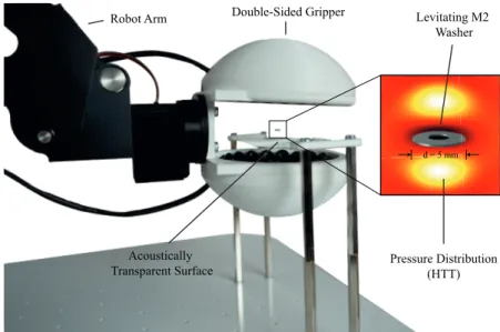
Acoustic levitation thus allows objects of any material to be transported and positioned without mechanical contact, i.e., with low stress on the object, and without contamination. However, the transport range is limited to the range of the acoustic field. To increase this range, the device that generates the acoustic field can be mounted to a robot arm to form a gripper, as shown in Figures1 and2[16].
Proceedings2020,64, 40; doi:10.3390/IeCAT2020-08510 www.mdpi.com/journal/proceedings
Double-Sided Gripper
Pressure Distribution (HTT) Robot Arm
Acoustically Transparent Surface
Levitating M2 Washer
d = 5 mm
Figure 1.Double-sided gripper arrangement capable of picking objects with a density of >7 g/cm3 from acoustically transparent surfaces using a horizontal twin trap (HTT). The system is mounted to a robot arm for long-range movements.
Robot Arm
Single-Sided Gripper
Levitating Object
Pressure Distribution (VTT)
Figure 2.Single-sided gripper arrangement capable of picking objects from acoustically reflective and transparent surfaces using standing waves and vertical twin traps (VTTs).
The controlled automated insertion of objects into the acoustic field is one of the most challenging tasks required for the implementation of an acoustic gripper. This work demonstrates such an implementation for different environments, namely for an object placed on acoustically transparent and reflective surfaces.
2. Materials and Methods
An array of piezoelectric transducers of type MSO-P1040H07T is used to generate the acoustic levitation field. The acoustic pressure generated by thejthtransducer of the array at a given point in space is calculated as
pj=eiφVRMSP0J0(krsinθ)
d eikd, (1)
whereφ,VRMS,P0,J0,d,θ,r, andk= 2πf/c0denote the phase of the transducer excitation signal, the RMS value of the excitation signal, a factor depending on the transducer type, the Bessel function of order zero, the distance of the considered point to the transducer, the beam angle, the radius of
Proceedings2020,64, 40 3 of 10
the transducer, and the wave number, respectively [15]. In the latter, f andc0denote the excitation frequency and the speed of sound in the considered medium (air), respectively. According to the Gor’kov potential [17], which is a potential function that describes the acoustic forces exerted on a spherical particle with radiusamuch smaller than the acoustic wavelengthλ, the acoustic forces acting on a suspended particle scale proportional to the square of the pressure magnitude, which is, in turn, proportional to the magnitude of the transducer excitation voltageV, yield
F∝|p|2∝V2. (2)
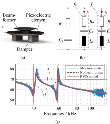
The peak pressure value generated by a piezoelectric electroacoustic transducer is proportional to the deflection of its vibrating element. The deflection is measured normal to the surface in thex direction, as shown in Figure3a, and depends on the charge stored in the piezoelectric element [18].
The current flowing through the piezoelectric element is therefore the relevant electrical quantity for generating pressure. The corresponding equivalent circuit based on a Butterworth–Van Dyke (BVD) model [19] is shown in Figure3b. Whether a square wave or sinusoidal voltage signal is applied to the transducers has no significant effect on the resulting pressure, since the frequency-dependent impedance of the transducers, as shown in Figure3c, suppresses the higher-order harmonics of the square wave signal. The relationship between the 40 kHz component of the applied electrical voltage V40and the resulting peak pressure value ˆpis given by
ˆ
p∝vˆ∝xˆ∝Qˆ ∝iˆ= V40
Z40, (3)
wherev,Q,i, andZ40denote the particle velocity of the sound wave, the charge stored in the transducer, the current flowing through the transducer, and the impedance of the transducer at 40 kHz, respectively.
The hat notation refers to the peak values of these quantities. The phase of the pressure is modified by adjusting the phase of the transducer excitation signal. The pressure magnitude is modified by adjusting the duty cycle of the square wave voltage signal. By providing an individual excitation signal for each transducer, it is possible to adjust the acoustic power and phase of each transducer individually. The transducers are arranged in arrays of various shapes and held in place by means of a 3D-printed holder.
To achieve a pressure distribution that facilitates levitation of an object in free space, the phase for each transducer has to be chosen such that the pressures generated by the individual transducers constructively superimpose at a focal point corresponding to the desired levitation position. This is achieved by calculating the phases of the individual excitation signals as
ϕ=−6 P0
ddei
2πf dd
c0 +RP0
drei
2πf dr c0
, (4)
where the reflection coefficient of an acoustically reflective surface in the acoustic fieldR = 0 [15].
The factor P0 = 0.26 Pa·m/VRMS for the transducers used in this work [20]. Further, dd anddr
denote the distance between the transducer and the focal point for the direct and reflected acoustic wave (see Figure 4), respectively. An acoustic trap is then created by adding a phase signature, which depends on the type of trap, to the phases that are used to generate the focal point [15,21]. In this work, mainly twin traps are used to trap the levitating objects. These are generated by applying a phase shift of 180◦to one half of the transducers in the array. Separating the transducers of the array by a horizontal plane results in a trap subsequently referred to as a horizontal twin trap (HTT). Separating the two halves by a vertical plane accordingly results in a vertical twin trap (VTT).
(b) (a)
x Beam- former
Damper
Piezoelectric element
Rp Cp
I0 I1
R0 C0 L0
R1 C1 L1 f0 f1
(c)
Frequency / kHz
40 60 80 100
50 80 70 60
Measurements No beamformer BVD model
Figure 3. MSO-P1040H07T piezoelectric transducer: (a) Annotated rendering of the mechanical structure. (b) Electrical equivalent circuit diagram Butterworth–Van Dyke (BVD) model showing the resonance paths atf0=40 kHz andf1=55 kHz. (c) Measured magnitude of the impedance and fitted BVD model.
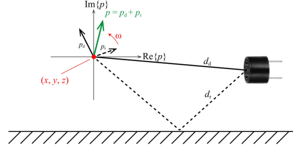
If an acoustically reflective surface is present within the acoustic field, the pressure generated by a single transducer at a point contains an additional component caused by the reflected wave (R6=0).
The total pressure oscillation has the same frequency as the pressure oscillation without the reflection, but the phase and magnitude are different. This can be illustrated by means of a pointer diagram, as shown in Figure4. If the direct pressure componentpdis constructively superimposed with the reflected pressure componentpr, a higher pressure amplitude is achieved. Due to the change in phase, the control must be adjusted according to Equation (4) withRset to the appropriate value. If the transducer arrangement is shifted relative to the reflecting surface, the influence of the reflected wave on the phase ofpchanges, which has to be taken into account by the control.
Using the reflection of sound waves on a surface, a standing wave can be formed between the transducers and the surface by focusing the acoustic pressure on the surface. The distance between the oscillating elements of the transducers and the reflecting surface should be a multiple ofλ/2 to achieve a high resulting pressure [22,23].
A distribution of the maximum attainable pressure (DMAP) describes the distribution that assumes a constructive superposition of all acoustic pressure sources at each point in space. It is calculated for each point by
M(x,y,z) =
∑
j
VRMSP0 J0(krsinθd,j)
dd,j +RJ0(krsinθr,j) dr,j
!
, (5)
whereθd,j,θr,j,dd,j, anddr,jdenote the beam angle of the direct path, the beam angle of the reflected path, the distance of the direct path between the considered point in space(x,y,z)and the transducer, and the distance of the reflected path between (x,y,z) and the transducer for the jth transducer, respectively. In environments without reflective surfaces, the DMAP is approximately constant,
Proceedings2020,64, 40 5 of 10
i.e., the attainable pressure is approximately the same at each point in space, as shown in Figure5a.
This means that it is possible to focus the pressure at each point.
dr
dd
p = pd + pr
pr
pd
Re{p}
Im{p}
(x, y, z)
ω
Figure 4.Direct (solid line) and reflected (dashed line) pressure components for a single transducer that are superimposed depending on the relative position of the transducer with respect to the reflecting surface, and total pressure generated by the transducer (green).
Two different transducer arrangements (arrays) are used in this work. The double-sided array consists of two pole caps of a sphere, each equipped with 36 transducers arranged in three rings of 6, 12, and 18 transducers. All transducers are oriented such that they point towards the center of the sphere. This arrangement is shown in Figure1. The single-sided array, as depicted in Figure2, has a cylindrical shape. Three rings of 6, 12, and 18 vertically oriented transducers are located at the horizontal top face of the arrangement. On the side walls of the cylinder, three rings of 20 horizontally oriented transducers each are located.
The transducers are controlled by a field-programmable gate array (FPGA) board generating 72 and 96 logic square wave signals for the double-sided and single-sided array, respectively. Resolutions of 0.5◦and≈1 % are achieved for the phase and duty cycle, respectively. The logic signals are then amplified by gate driver integrated circuits (ICs) and applied to the transducers. The duty cycle and the phase are calculated on a personal computer (PC) for each transducer and transmitted to the FPGA board via a universal asynchronous receiver–transmitter (UART) interface.
3. Results and Discussion
The procedure for automatically inserting an object into the acoustic field depends on the properties of the object and its environment. The higher the density of the object and the lower the transmission coefficient of the surface on which the object is located, the more difficult it is to lift the object off the surface.
As long as the transmission coefficientT of the surface is large enough (T > 50%) and there is sufficient space on both sides of the surface, a double-sided arrangement that can generate high forces in the vertical direction can be used. Such surfaces are subsequently referred to as acoustically transparent. If the transmission coefficient is low (T<50%), the surface is referred to as acoustically reflective. Procedures are presented that allow stable and smooth lifting of objects from acoustically transparent and reflective surfaces.
If the object is located on an acoustically transparent surface, the array is moved close to the object to be picked in the turned-off state. The transducers are then controlled such that the object is located in an acoustic trap. Subsequently, the acoustic power is increased.
The control is identical to that used when the object is levitated at the position of the acoustic trap. The influence of the surface on the control can be neglected ifTis high. By adjusting the control, the pressure field is manipulated such that the object moves in the vertical direction and, afterwards,
the arrangement is moved away from the surface. Alternatively, if there are no objects that restrict a vertical movement of the gripper, the arrangement can be moved vertically without adjusting the control and moved away from the surface afterwards.
With this method, the picking of objects with a density >7 g/cm3 using a double-sided arrangement, as depicted in Figure1, was demonstrated. In order to improve the repeatability of the process, the acoustic power can be increased continuously during the power-on process, such that no sudden forces are exerted on the object. As the gripper is moved away from the surface, low-frequency disturbances of the pressure field cause vibrations of the levitating object [24]. These vibrations are weakly damped by air friction. The magnitude of these vibrations depends on the magnitude of the transducer excitation signal. In order to minimize vibrations, the acoustic power can be reduced as long as the vertical force is still sufficient to counteract the gravitational force acting on the object.
Compared to picking an object from an acoustically transparent surface, it is more demanding to pick objects from acoustically reflective surfaces. The reflection of incident wavesYi on a reflective surface does not cause a phase shift. If the incident wave arrives perpendicular to the surface, the superposition between the incident waveYiand the reflected waveYrcauses a minimum to be formed at a distance ofλ/4 from the surface, as shown by Equations (6)–(8) [22,23].
Yi(t,z) =Asin
ωt−2πz λ
(6)
Yr(t,z) =Asin
ωt+2πz λ
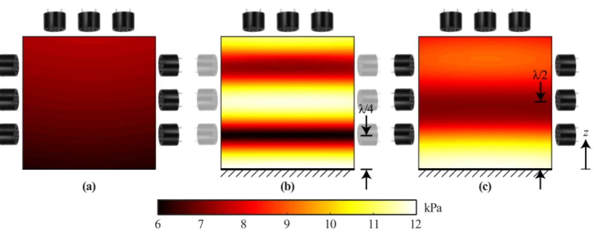
(7) Yi(t,λ/4) +Yr(t,λ/4) =Asin(ωt−π/2) +Asin(ωt+π/2) =0 (8) If the acoustic sources are located far away from the surface, the acoustic waves are perpendicularly incident upon the surface. The DMAP for transducers on the horizontal top of the single-sided arrangement, which are located at a distance of 3.5λfrom the reflective surface, is shown in Figure5b. Due to the minimum being formed atz=λ/4 above the reflective surface, it is not possible to focus the pressure around this location, which would be necessary to generate a twin trap.
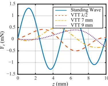
If the transducers are located closer to the surface, the distance at which destructive superposition occurs deviates from λ/4, and the minimum of the DMAP is attenuated. This is shown for the single-sided arrangement in Figure5c. With this arrangement, it is possible to focus the pressure for z≥λ/2. Therefore, a VTT can be generated atz=λ/2, as shown in Figure6b. The forces generated by this trap pull the object into the acoustic trap if the vertical force generated by this trap is larger than the gravitational force. This is the case atz = λ/4 for all objects that can be lifted with this arrangement, as shown in Figure7.
By generating a standing wave, it is possible to levitate objects in a stable manner atz≈ λ/4, however, without the possibility to move the object vertically. Nevertheless, it is possible to switch from a standing wave to a VTT located atz=λ/2 that pulls the object upwards. Taking into account the reflections at the surface, the control can then be adjusted such that the object is moved away from the surface until reflections become negligible and the array can be moved away from the surface without further adjustments of the control. An array for this process requires vertically oriented transducers to generate a standing wave and horizontally oriented transducers to generate a VTT.
The forces and force potentials during the process resulting for the single-sided array are shown in Figures6and7.
Proceedings2020,64, 40 7 of 10
(a) (b) (c)
λ/4
λ/2
z
6 7 8 9 10 11 12kPa
Figure 5.Distribution of maximum attainable pressure (MAP) for (a) a single-sided array in free space, (b) the top part of the single-sided array with an acoustically reflecting surface atz=0 exhibiting high gradients that prohibit the generation of arbitrary focal points, and (c) the single-sided arrangement with an acoustically reflecting surface atz=0 with a gradient that allows manipulation above a height ofz=λ/4.
) b ( )
a (
) d ( )
c (
/4 /2
7 mm 9 mm
10 mm
x z
ȝJ ȝJ
ȝJ ȝJ
Figure 6.Force potential for (a) a standing wave with a minimum atz=λ/4 and VTTs at (b)z=λ/2, (c)z=7 mm, and (d)z=9 mm. The potentials are obtained for an acoustically reflective surface at z=0.
0 2 4 6 8 10
−1.5
−1
−0.5 0 0.5
1 1.5
z (mm) F
z(mN)
Standing Wave VTT λ/2 VTT 7 mm VTT 9 mm
Figure 7. Vertical forces for a standing wave with a minimum atz = λ/4 and VTTs atz = λ/2, z=7 mm, andz=9 mm. The forces are obtained for an acoustically reflective surface atz=0.
To perform the picking process in a continuous fashion, the power of the vertically oriented transducers is first increased continuously, raising the object smoothly toz = λ/4. Subsequently, using stepwise phase changes, the standing wave is altered to a VTT. Finally, by using small steps to shift the location of the trap in the vertical direction, the object is moved further away from the surface while the stress on the object is minimized.
Based on the presented results, it is possible to use acoustic grippers for process automation.
The shown concepts are applicable for different environments of the gripped object and facilitate the minimization of the stress through an object-dependent adjustment of the acoustic power.
The flexibility of the presented systems can be extended further by sensors that detect the position of the object.
Picking of objects with a density ofρ > 7 g/cm3from acoustically transparent surfaces was demonstrated. A gripped steel washer with a diameter ofd=5 mm and a density ofρ=7.8 g/cm3is shown in Figure1. For reflective surfaces, the density of the picked object was limited toρ=0.25 g/cm3 due to the small vertical forces generated by VTTs.
The use of transducers that are capable of generating high pressures over a wide range of frequencies would facilitate vertical movements of objects trapped in a standing wave. Using such transducers would allow objects with a higher density to be picked from a reflective surface, which would open up further fields of application.
Funding:This research received no external funding.
Abbreviations
The following abbreviations are used in this manuscript:
VTT Vertical Twin Trap HTT Horizontal Twin Trap
DMAP Distribution of Maximum Attainable Pressure FPGA Field-Programmable Gate Array
UART Universal Asynchronous Receiver–Transmitter IC Integrated Circuit
PC Personal Computer BVD Butterworth–Van Dyke
Proceedings2020,64, 40 9 of 10
References
1. Santesson, S.; Nilsson, S. Airborne chemistry: Acoustic levitation in chemical analysis.Anal. Bioanal. Chem.
2004,378, 1704–1709, doi:10.1007/s00216-003-2403-2.
2. Xie, W.J.; Cao, C.D.; Lü, Y.J.; Hong, Z.Y.; Wei, B. Acoustic method for levitation of small living animals.
Appl. Phys. Lett.2006,89, 214102, doi:10.1063/1.2396893.
3. Weber, J.K.R.; Benmore, C.; Tumber, S.; Tailor, A.; Rey, C.; Taylor, L.; Byrn, S. Acoustic levitation: Recent developments and emerging opportunities in biomaterials research. Eur. Biophys. J. EBJ2011,41, 397–403, doi:10.1007/s00249-011-0767-3.
4. Puskar, L.; Tuckermann, R.; Frosch, T.; Popp, J.; Ly, V.; McNaughton, D.; Wood, B.R. Raman acoustic levitation spectroscopy of red blood cells and Plasmodium falciparum trophozoites. Lab Chip2007,7, 1125–1131, doi:10.1039/B706997A.
5. Sundvik, M.; Nieminen, H.J.; Salmi, A.; Panula, P.; Hæggström, E. Effects of acoustic levitation on the development of zebrafish, Danio rerio, embryos. Sci. Rep.2015,5, 13596, doi:10.1038/srep13596.
6. Seddon, A.M.; Richardson, S.J.; Rastogi, K.; Plivelic, T.S.; Squires, A.M.; Pfrang, C. Control of Nanomaterial Self-Assembly in Ultrasonically Levitated Droplets.J. Phys. Chem. Lett.2016,7, 1341–1345, doi:10.1021/acs.jpclett.6b00449.
7. Foresti, D.; Sambatakakis, G.; Bottan, S.; Poulikakos, D. Morphing Surfaces Enable Acoustophoretic Contactless Transport of Ultrahigh-Density Matter in Air. Sci. Rep.2013,3, 3176, doi:10.1038/srep03176.
8. Nordine, P.C.; Merkley, D.; Sickel, J.; Finkelman, S.; Telle, R.; Kaiser, A.; Prieler, R. A levitation instrument for containerless study of molten materials. Rev. Sci. Instruments2012,83, 125107, doi:10.1063/1.4770125.
9. Yan, N.; Hong, Z.Y.; Geng, D.; Wei, B. A comparison of acoustic levitation with microgravity processing for containerless solidification of ternary Al–Cu–Sn alloy.Appl. Phys. A2015,120, doi:10.1007/s00339-015-9151-y.
10. Ohsaka, K.; Trinh, E. Three-Lobed Shape Bifurcation of Rotating Liquid Drops. Phys. Rev. Lett. 2000, 84, 1700–1703, doi:10.1103/PhysRevLett.84.1700.
11. Shen, C.; Xie, W.; Wei, B. Parametrically excited sectorial oscillation of liquid drops floating in ultrasound.
Phys. Rev. E Stat. Nonlinear Soft Matter Phys.2010,81, 46305, doi:10.1103/PhysRevE.81.046305.
12. Bleuler, H.; Cole, M.; Keogh, P.; Larsonneur, R.; Maslen, E.; Okada, Y.; Schweitzer, G.; Traxler, A.
Magnetic Bearings: Theory, Design, and Application to Rotating Machinery; Springer: Berlin/Heidelberg, Germany, 2009.
13. Kundt, A. Über eine neue Art akustischer Staubfiguren und über die Anwendung derselben zur Bestimmung der Schallgeschwindigkeit in festen Körpern und Gasen. Ann. Phys. 1866,203, 497–523, doi:10.1002/andp.18662030402.
14. Tian, Y.; Holt, R.G.; Apfel, R.E. A new method for measuring liquid surface tension with acoustic levitation.
Rev. Sci. Instruments1995,66, 3349–3354, doi:10.1063/1.1145506.
15. Marzo, A.; Seah, S.A.; Drinkwater, B.W.; Sahoo, D.R.; Long, B.; Subramanian, S. Holographic acoustic elements for manipulation of levitated objects. Nat. Commun.2015,6, 1–7, doi:10.1038/ncomms9661.
16. Nakahara, J.; Yang, B.; Smith, J.R. Contact-less manipulation of millimeter-scale objects via ultrasonic levitation.arXiv2020, arXiv:2002.09056.
17. Gor’kov, L.P. On the Forces Acting on a Small Particle in an Acoustical Field in an Ideal Fluid.Sov. Phys. Dokl.
1962,6, 773.
18. Fabijanski, P.; Lagoda, R. Modeling and Identification of Parameters the Piezoelectric Transducers in Ultrasonic Systems, Advances in Ceramics—Electric and Magnetic Ceramics, Bioceramics, Ceramics and Environment. Adv. Ceram. Electr. Magn. Ceram. Bioceram. Ceram. Environ.2011, 155–176, doi:10.5772/21619.
19. Uzunov, I.S.; Terzieva, M.D.; Nikolova, B.M.; Gaydazhiev, D.G. Extraction of modified butterworth—Van Dyke model of FBAR based on FEM analysis. In Proceedings of the 2017 26th International Scientific Conference Electronics, ET, Sozopol, Bulgaria, 13–15 September 2017, doi:10.1109/ET.2017.8124394.
20. Marzo, A.; Barnes, A.; Drinkwater, B.W. TinyLev: A multi-emitter single-axis acoustic levitator.
Rev. Sci. Instruments2017,88, doi:10.1063/1.4989995.
21. Marzo, A.; Caleap, M.; Drinkwater, B.W. Acoustic Virtual Vortices with Tunable Orbital Angular Momentum for Trapping of Mie Particles. Phys. Rev. Lett.2018,120, 044301, doi:10.1103/PhysRevLett.120.044301.
22. Kandemir, M.H.; Çalı¸skan, M. Standing wave acoustic levitation on an annular plate. J. Sound Vib.2016, 382, 227–237, doi:10.1016/j.jsv.2016.06.043.
23. Zhao, S.; Wallaschek, J. A standing wave acoustic levitation system for large planar objects.Arch. Appl. Mech.
2011,81, 123–139, doi:10.1007/s00419-009-0401-3.
24. Croft, J.J.; Norris, J.O.Theory, History, and the Advancement of Parametric Loudspeakers, A Technology Overview;
American Technology Corporation: San Diego, CA, USA, 2001.
Publisher’s Note:MDPI stays neutral with regard to jurisdictional claims in published maps and institutional affiliations.
© 2020 by the authors. Licensee MDPI, Basel, Switzerland. This article is an open access article distributed under the terms and conditions of the Creative Commons Attribution (CC BY) license (http://creativecommons.org/licenses/by/4.0/).