Journal Article
Stacking-fault mediated plasticity and strengthening in lean, rare-earth free magnesium alloys
Author(s):
Basu, Indranil; Chen, Ming; Wheeler, Jeffrey; Schäublin, Robin E.; Löffler, Jörg F.
Publication Date:
2021-06-01 Permanent Link:
https://doi.org/10.3929/ethz-b-000479922
Originally published in:
Acta Materialia 211, http://doi.org/10.1016/j.actamat.2021.116877
Rights / License:
Creative Commons Attribution-NonCommercial-NoDerivatives 4.0 International
This page was generated automatically upon download from the ETH Zurich Research Collection. For more information please consult the Terms of use.
ETH Library
Acta Materialia 211 (2021) 116877
ContentslistsavailableatScienceDirect
Acta Materialia
journalhomepage:www.elsevier.com/locate/actamat
Full length article
Stacking-fault me diate d plasticity and strengthening in lean, rare-earth free magnesium alloys
I. Basu
a,∗, M. Chen
b, J. Wheeler
b, R.E. Schäublin
a, J.F. Löffler
a,∗aLaboratory of Metal Physics and Technology, Department of Materials, ETH Zurich, 8093Zurich, Switzerland
bLaboratory for Nanometallurgy, Department of Materials, ETH Zurich, 8093Zurich, Switzerland
a rt i c l e i nf o
Article history:
Received 17 December 2020 Revised 12 March 2021 Accepted 3 April 2021 Available online 7 April 2021 Keywords:
Magnesium Twin nucleation dislocation analysis Chemical ordering Stacking-fault energy
a b s t r a c t
AmagnesiumalloywithleanadditionsofZn(1wt.%)andCa(0.3wt.%),ZX10,andpureMgweresub- jectedtoorientation-dependentmicropillarindentationtestsatambienttemperature.Single-crystalline micropillarsoftwodifferentorientationswerefabricatedtoactivateextensionandcompressionalongthe c-axis,respectively.Forbothloadingconditions,ZX10exhibitsastrengtheningincrementbyafactorof2 to2.5comparedtopureMgalongwithplasticityenhancement.Correlativetransmissionelectronback- scattereddiffractionandtransmissionelectronmicroscopyrevealthatdeformationinZX10proceedsby deformationtwinningunderc-axisextension,generatinghomogeneousactivationofbasalandnon-basal slipathigherstrains.Incontrast,pureMgdisplaysdeformationthroughtensiontwinningandbasalslip.
Pure Mgunderc-axiscompression deformsbybasal dislocation-mediatedmassive sliding,whileZX10 revealsdualactivationofbasalaand pyramidalc+adislocations.Mechanistically,theminuteaddi- tionsofZnandCasolutesmodifytheintrinsicstacking-faultenergy,whichaccountsforthesimultaneous strengtheningandductilityenhancement.Thesefindingshighlightthebeneficialimpactofdiluteaddi- tionsofZnandCainactivatingnoveldeformationpathwaysthatarecriticalfordesigningrare-earth(RE) freehigh-strength,highlyductilemagnesiumalloysforstructuralandbiomedicalapplications.
© 2021 The Author(s). Published by Elsevier Ltd on behalf of Acta Materialia Inc.
ThisisanopenaccessarticleundertheCCBY-NC-NDlicense (http://creativecommons.org/licenses/by-nc-nd/4.0/)
1. Introduction
The past decade has witnessed a renewed interest in lightweight magnesium (Mg)alloys, stimulatedby urgentweight- saving and thereby energy-saving requirements in automo- tive, aerospace and communication industries [1-6]. Despite the tremendousunderlyingpotential forMgalloystoemergeasnext- generation structural materials, their widespread useis consider- ably limited owing tothe overarching problemof poorstrength- ductility synergy[7].Presentmagnesium alloysshow limitedcold formability dueto their restricted plasticityat ambienttempera- tures, primarily stemming from: (i) the absence of five or more independent deformation modes required to fulfil the von-Mises criterion forhomogeneous plasticdeformation, and(ii)thegener- ation of strong crystallographic textures duringdeformation that promotemechanicalanisotropy[2,8-11].Bothoutcomesarefunda- mentally attributedtothe low crystalsymmetry inan hexagonal
∗Corresponding authors.
E-mail addresses: indranil.basu@mat.ethz.ch (I. Basu), joerg.loeffler@mat.ethz.ch (J.F. Löffler).
close-packed(hcp)structure,whereinstrainaccommodationalong thea-axis(i.e.on(0002)basalplanes) isstronglypreferredwhile slipdeformationalongthec-axis(i.e.onnon-basalplanes)isdiffi- culttoactivate[2,8].
Numerous studies have indicated that through intelligent al- loyingandappropriatethermomechanicaltreatmenttheactivation andstabilityofdislocationsandslipsystemscan bemanipulated, such that Mg alloys can display intrinsic improvements in their room-temperature plasticityresponse [10,12-15]. Thishas inpar- ticularbeenestablishedforMgalloyswithdiluteadditionsofrare- earth elements (REEs), where their presence promotes the rela- tive activity of non-basal slip, i.e. pyramidal
c+a dislocations, whichprovide an out-of-basal plane shear[3,12,16,17]. Moreover, activationofpyramidalslipprovidesfiveindependentdeformation modes,givingrisetohomogeneousplasticityandstrain-hardening response[8].Despitethe advantagesofMg–RE-basedalloys,their commercialapplicationsareratherlimited,owingtoanexpensive andcumbersomeprocessingschemepluspoorrecyclability[18,19].In order to mitigate the aforementioned issues, the Mg-research communityhaslatelyshowngreatinterestinthesearchofalterna- tivelow-cost REE-freeMgalloys. Thishasmotivatedthedevelop-
https://doi.org/10.1016/j.actamat.2021.116877
1359-6454/© 2021 The Author(s). Published by Elsevier Ltd on behalf of Acta Materialia Inc. This is an open access article under the CC BY-NC-ND license ( http://creativecommons.org/licenses/by-nc-nd/4.0/ )
Mg–Ca-based alloys andits impact on intrinsic plasticitymecha- nisms isratherincomplete. Instudies ofCa-containingMg alloys thatdatebackmorethantwodecades,theprimaryfocuswasand still ispinnedupontheprecipitation-hardeningresponse inthese alloys[19,33,34].
Thepresentworkattemptstounravelthekeyplasticitymecha- nismsinMg–Zn–Caalloyswithspecialemphasisontheroleofso- luteCaandZnatomsinmodifyingthedeformationresponse.Pure Mg is used as a reference material in this study. A combination ofmicrocompressiontestingandcorrelativeelectronmicroscopyis implementedtoprobethestructure-propertyrelationships.Inpar- ticular,definitecorrelationsbetweensolutearrangementintheMg matrixanditsresultantinfluenceonthespatialdistributionofde- fectsareestablished.Moreover,theinfluenceofalloyingelements ontheslipandtwinningdeformationisassessedbothqualitatively andquantitatively.
2. Experimentalmethods
As-extrudedMg-1wt.%Zn-0.3wt.%Ca (ZX10)alloys(moredetails in Ref. [24])were solutionizedat520 ◦C for2 hrs todissolve all Zn andCain theMgmatrix.The specimenswere thencut along thetransversedirectionsuchthattheviewingplanewasparallelto theextrusiondirection.Forthepurposeofcomparison,specimens were also cut from as-cast, homogenized commercially-pure Mg.
Toobtainthesizedistributionandorientationofthegrainswithin themicrostructure,conventionalelectronback-scattereddiffraction (EBSD) measurements were performed using an FEI Quanta 200 field-emission gun scanning electron microscope (SEM) equipped with an EDAXTMHikariEBSDcamera. The specimens forEBSDon both ZX10 andpure Mg were prepared using conventional met- allography techniques, with Ar+ broad ion-beam milling (Hitachi IM4000) as a final step. The broad ion-beam milling was per- formed in two steps, where an initial short-duration ion-beam etchingremovedthetopdamagedlayerresultingfrompreparatory grinding,andasubsequentlong-durationpolishingwasperformed atlowacceleratingvoltage(2kV)underagrazing-incidenceangle.
Two grain orientations, i.e.
10¯10 || CD and 0002 || CD(whereCDdenotesthecompressiondirection;TDisthetransverse direction), were selected forboth pure MgandZX10 tofabricate specially orientedsingle-crystalline micro-pillars,using a Ga+ fo- cusedion-beam(HeliosNanolab600i)operatedatanaccelerating voltage of30kV. Foreach condition, i.e.orientationandmaterial type, at least sixindividual pillars withdiameters of 2
μ
m andheightsof5
μ
mweremilled.Threedifferentmillingcurrentswereemployed:9.4nAforcoarsemilling,followedbyamediumcurrent of0.77nAtodimensionthepillarclosetothedesignedgeometry, and a final surface polishing with 33 pA to minimize the taper, suchthataresultanttaperangleof<1◦ wasachieved.
thefirstexcursionfromthelinearstress-strainresponse.Thecriti- calresolvedshear-stressescorrespondingtotheactivedeformation mode were quantified by multiplying the measured yield stress withtheSchmidfactoroftheactiveslipsystem.Inordertoeval- uatethe plasticitymechanisms asa function ofstrain, additional micro-pillarcompressiontestswere stoppedatintermediate plas- ticstrainvalues.
Nanoscale structural characterization of the micropillars com- pressedtoselectedstrainswasperformedusingcorrelativetrans- mission EBSD (t-EBSD) and transmission electron microscopy (TEM). Cross-sections of deformed micropillars were prepared using standard lift-out techniques in the FIB using a micro- manipulator. The cross-sections were thinned down to electron transparency with graded reduction of milling voltage and cur- rent,withthefinal polishingstepperformedat2kVforamilling current of 10 pA. t-EBSD measurements were performed in the FEIQuanta200FEG-SEM atan acceleratingvoltageof30kVand a beam spot size of 4 nm. The specimen was tilted at an an- gle of −5◦, and a step size of 10 nm anda hexagonal grid type wasimplemented. Abinning of 4 × 4was usedwhen capturing theKikuchipatterns,producing a320× 240CCDcamera resolu- tion.TheacquiredrawEBSDdatawassubsequentlyanalyzedusing EDAX-TSL OIMTM Analysis 8 software and an MTEX Matlabtool- box[35].Inordertoachievehighindexingrates,therawunfiltered EBSDdatawasreindexedemployinganeighborhood-patternaver- aging(n-PAR)schemetoimprovethepattern’ssignal-to-noiseratio [36].Then-PARalgorithmisavailableasabuilt-infunctioninthe conventional EBSDanalysis softwareOIMTM Analysis 8.Noise fil- teringwasperformedwithathresholdconfidenceintervalof0.2.
TEMimaging of the micropillar cross-sections wasperformed ina JEOLJEM-1400transmissionelectronmicroscope operatedat 120kVusingaJEOLdouble-tiltsampleholder.Elementaldistribu- tionmapswererecordedbyelectrondispersiveX-rayspectroscopy (EDS)measurementsthatwereconductedusinganFEITalos200X transmissionelectronmicroscope,operatedat200kV,withanin- built FEI Super X detector equipped with large-collection angles technology.
In order to identify the active dislocation and stacking-fault mechanisms,aquantitativeinterpretationofTEMmicrographswas accomplishedbymeansofTEMimagesimulationsoftheobserved straight dislocation lines and stacking faults in Mg. We consid- eredonedislocationborderingonestackingfault.Simulationswere performed using CUFOUR software, which combines the many- beam Schäublin–Stadelmann equations to describe the propaga- tion of the electron beam in the TEM thin foil and anisotropic elasticityto describe the deformation ofthe material around de- fects [37]. The general computational sequence in CUFOUR con- sists of three main parts: (i) preprocessing of geometrical and physicalparametersinput todescribethe sampleconditions(ma-
I. Basu, M. Chen, J. Wheeler et al. Acta Materialia 211 (2021) 116877
Fig. 1. Engineering stress-strain curves for the alloy ZX10 (filled blue circles) and pure Mg (empty blue circles) from micropillar compression tests activiating c-axis extension . The regions are twinning-dominated (highlighted in green) and slip-dominated plasticity. The stress-drop events correspond to either twinning or slip avalanches. SEM images of pillars deformed to final strain are additionally shown on the right for pure ZX10 (top) and pure Mg (bottom). The crystallographic orientations of the twins and parent grains are depicted for pure Mg; the basal- a slip traces are revealed by black arrow heads and the {10 ¯1 0 } prismatic- a slip traces are shown by yellow ones.
terial type, lamella condition) containing the defects of interest;
(ii) solving Schäublin–Stadelmann equations; (iii) postprocessing of the simulated TEM image. The physical parameters for de- scribing the orientation of the TEM lamella inside the micro- scope were carefully chosen. The electron beam direction, the foil normaland thediffractioncondition, which includes theop- erating diffraction vector and its excitation, were matched with the experiments according to the electron diffraction patterns.
The corresponding defect configuration made up of one disloca- tion bording one stacking fault waschosen amongall those that are found in hexagonal metals including Mg. This includes: the dislocation Burgers vector, the dislocation line, the stacking-fault habit plane and the lattice translation across the stacking fault.
The simulated image that best matches the experimental image thenrevealstheexactdislocation–stacking-faultconfiguration.The thickness of the foil was established by matching the simulated andexperimentalimages.Theconsideredelastic constantsforMg [38] were: C11=C22=59.4GPa, C12=25.6GPa, C13=21.4GPa, C33=61.6GPa,C44=C55=16.4GPa,C66=16.9GPa.
3. Results
3.1. Stress-strainresponseundermicropillarcompression
Fig.1showstheengineeringstress-strainresponseofZX10un- der c-axis extensionin comparisonto themechanical response of pure Mg under the same loading conditions. The initial stress- strain responses for both ZX10 and pure Mg are similar, with the onset of plasticity inboth casesoccurring at a strain of
ε
≈ 0.75% (with a corresponding stress of ~ 120 MPa). As the im- posedstrainbecomeslargerthanε
≈1.5%,thehardeningresponse of ZX10markedlyincreases(highlighted bya blackdouble-edged arrow in Fig. 1) and deviates from the trend exhibited by pure Mg,culminatingintoasharploaddropatε
≈2%.Thisissucceeded by a short stress plateau, which typically indicates the onset of twinning activity and has been well established in earlier stud- ies[39,40].Such characteristicallysimilarstressspikes occurmul- tiple times up to a strain ofε
≈7%. Fig. 1 highlights the twin- nucleation andtwin-growtheventsbygreen andblue arrows,re- spectively. At higher strains,the stress-strain curve showsmulti- plehardeningregimesinterspersedwithsoftening,highlightedby a seriesof stress drop events. Loading under c-axis extension forpure Mg exhibitsqualitatively similar behavior as seen forZX10, corresponding to twinning-dominateddeformation up toa strain of
ε
≈7%.However,thehardeningrateissignificantlylowercom- paredtoZX10.Thestress-strainresponseathigherstrainsishigh- lightedbyalternatinghardeningandsofteningbehavior untilfail- ureatε
≈29%.SEM micrographs of the micropillars deformed to final strain areshownontheright-handsideofFig.1.Thebottomrightimage representsthespecimengeometrycorrespondingtothe deforma- tion of pure Mg under c-axis extension. Geometrically, the post- deformation pillar aspect ratio is significantly modified, as indi- catedbyareducedheightandaslightexpansionalongthelateral dimension. Deformationis dominated by twinning,giving rise to twotensiontwinvariantsasshownbythe60°misorientation be- tweenthebasalplanesofadjacenttwins.Thetoppartofthepillar retainstheparentorientation, asrevealedbythetwinboundaries illustratedbywhitearrows.Intermsofdislocationslip,theparent grain showsslip tracescorresponding to prismatic
a slipactiv-ity.Bothtwinsundergoprofuse basal slip, illustratedby thehigh densityofbasalsliptraces.Incontrast,themicropillargeometryof theZX10alloy(showninthetoprightcornerofFig.1)appearsto retainitsinitialaspectratiowithrelativelylessdefinedexpansion alongthelateraldimension.However,thepillardisplaysabentge- ometry owingto a seriesof visiblydiscrete basal dislocation-slip shearing events, generating successive slip steps in the direction lateraltothepillar.
Fig. 2shows micropillar compressiontests forZX10 andpure Mg, correspondingto c-axiscompression.A loadingparallelto the
0002 direction clearly indicates higher elastic stiffness in thecase of pure Mg compared to ZX10. While the former reveals a yield stress of387 MPa, the latter shows a yield stress value of 323MPa.Thestrain incrementischaracterized bya higherhard- eningslopeforZX10comparedtopureMguptoastrainof
ε
≈5%, wherebothreachastressvalueof600MPa.Athigherstrains,pure Mg displays massive softening, where the stress drops to ~300 MPa.Incontrast,theZX10alloycontinuestoshow strainharden- ing with intermittent stress drops, reaching a maximum steady- statestressof~800MPa.Geometrically,thepureMgpillarunderc-axiscompressionun- dergoesmassive basal sliding,resulting ina strong misalignment betweenthe specimen andloading axes. Few instances of traces
Fig. 2. Engineering stress-strain curves for ZX10 (filled red circles) and pure Mg (empty red circles) from micropillar compression tests activiating c-axis compression . SEM images of pillars deformed to final strain are additionally shown on the right for ZX10 (top) and pure Mg (bottom). The crystallographic orientation of the pillar is depicted for pure Mg; the basal- a slip traces are revealed by a black arrow head, {10 ¯1 0 } prismatic a slip traces are shown by a yellow arrow head, and {11 ¯2 2 } pyramidal c + a slip traces are shown by a red one (see inset).
along the non-basal planes were also observed. An SEM micro- graphoftheas-deformedZX10micropillarillustrates significantly restrained lateral sliding, corroborating the greater work harden- ability inthe alloyedspecimencompared topure Mg(see movie showninSupplementaryFig.1).Conversely,theobservedpillardis- tortion in ZX10 most likely arises from uniform basal and non- basalslipoperation.Inaddition,micro-cracksoriginatingatthetop surfaceandpropagatingintothepillar(detailscanbeseeninSup- plementaryFig.1) areobservedalongtheprismatic planes(high- lightedbytheyellowarrowheadinFig.2).
Fig. 3 shows snapshots taken in situ in the SEM at different strainsforpureMgandZX10underthetwodifferentloadingcon- ditions,toillustratetheevolutionofthemicropillargeometryasa function of deformation strain. Fora detailed view onthe defor- mation progression, thereaderisreferred tothemovie shownin SupplementaryFig.1.Underc-axiscompression,theonsetofbasal- sliding-induced plasticinstabilityoccursinthepureMgmicropil- lar when the deformation strain increases from 5% to 10%. This event clearly correlates with the large stress drop in the stress- straindatashowninFig.2,whichoccursforstrainslargerthan5%.
Incomparison,theZX10micropillardoesnotrevealmassivedistor- tion inthepillargeometryuntiladeformation strainof10%, cor- roborating the significantly higher work-hardeningresponse seen inthestress-straincurve.
Inthecaseofc-axisextension,both theMgandZX10pillardo not revealanysliptracesupto adeformationstrain of5%, which is attributedto the initial twinning-mediated plasticity response forbothcases.Atlargerstrains,massivebasalshearsteps areob- served in pure Mg (already visible at a strain level of
ε
≈10%), whereas the appearance ofdiscrete basal slipsteps is delayedto 15%strain inthecaseoftheZX10alloy.Comparingthiswiththe stress-strain curves under c-axis extension, the pillar-shape evo- lution agreeswell withthe transitionfromtwinning-mediatedto slip-mediatedplasticityforstrainsgreaterthan7%.3.2. Strain-basedmicrostructuralevolutionofZX10underc-axis extension
In ordertoassessthe localplasticitymechanismsinthe ZX10 alloy as a function of imposed plastic strain, microstructural in- vestigations usingcorrelativetransmissionKikuchidiffractionand electronmicroscopy wereperformedalong thelongitudinalcross- section ofthepillars. Themicrostructuralcharacterizationwasfo-
cusedonthealloyedspecimen,becauseofitssuperiormechanical performancecomparedtopureMg.
Fig. 4 illustrates the strain-based deformation sub-structure evolution under c-axis extension. At a strain of 3%, the SEM im- ageindicatesthatthemid-sectionofthepillarhasundergone de- formation twinning (see Fig. 4a). The corresponding orientation map of the cross-section (highlightedby the dotted rectangle in Fig.4a)revealsthetwintobea
{
10¯12}
tensiontwin,whichreori-ents the c-axis of theparent grain nearly parallel to the loading axis. Fig. 4b shows the twinned grain in red in an inverse pole figure orientation map andsingle-orientation scatter pole figure.
Thenucleatedtwinisawell-knownhighSchmid-factortwinvari- ant, which mostly dominates twinning in pure Mg. Fig. 4b also presentsthekernelaveragemisorientation (KAM)mapforthere- gionin thevicinity ofthetwin-parentinterface. The KAMvalues are calculatedfor thesecond-nearest neighbourassuming an an- gularthresholdof2°[41].Theappearanceofgreenish-yellowcol- orsinthevicinityofthetwin-parentinterface indicatesstrainac- cumulation at the boundaries due to dislocation-twin boundary interactions. In addition,the parent orientation (shown in red in Fig. 4b) undergoes prismatic slip-induced rotation around the c- axisandthusdeviatesfromthestartingorientationof
10¯10||CDrepresentedinblue(seelegendinFig.4). Anin-grainmisorienta- tionaxis(IGMA)distributionmap showninSupplementary Fig.2 showsthattheaxial spreadinsidetheparentliesinbetweenthe
10¯10and11¯20directions,thusindicating thatthein-grainro- tationoccursaboutthec-axis.Fig.4cpresentsdark-fieldTEMmi- crographsofthemicropillar,revealingthedislocationstructuresin thetwinned andparentgrains.The twinned areaexhibitsa large density of sharp and narrow streaks that look like basal stack- ingfaults arrangedinalayered fashion,withmanyprismaticand pyramidalIdislocationsegmentsenclosedbetweenadjacentfaults, whichareobservednearthetwininterface.Theseobservationsare further validated by the image quality map (see inset), showing sliptraces corresponding to prismatic (shown by a yellowarrow inFig.4c)andpyramidalIplanes(shownbylight bluearrowsin Fig. 4c). The twin-parent interface reveals a complex dislocation structurethatmayrelate totheinteractionofstackingfaultswith thetwinboundary.Asthe deformationstrain increasesto6.5%, thetwinnedcrys- tal expandsto occupy themajority ofthe pillar (see Fig. 4dand Fig.4e).The whitedottedframe inFig. 4dindicates theplane of
I. Basu, M. Chen, J. Wheeler et al. Acta Materialia 211 (2021) 116877
Fig. 3. . In situ SEM snapshots of micropillar geometry at different intermediate deformation strains shown for pure Mg and ZX10, for both c-axis compression and c-axis extension.
observationforthe t-EBSDandTEManalyses. Simultaneouslythe twinnedgrainalsoexhibitsdeformationviadislocationslip,where the c-axis of the twin starts to rotate away from the compres- siondirection, indicativeofnon-basalslipactivity.Strainaccumu- lationatthetwin-parentinterfacesignificantlyescalates(asshown inSupplementaryFig.3),whichnucleateslowSchmid-factortwin variants represented in greenish-yellowcolor in the inverse pole
figure and single-orientation scatter plots of Fig. 4e (marked by whitearrowheads). Corresponding TEMmicrographsof thetwin boundary(seeFig.4f)indeedrevealtheappearance ofnano-scale twins(asconfirmedby theoverlappingdiffractionpatternsofthe parentindicatedbyawhitearrowandthenano-twinshownbya blackarrowinFig.4f),andthuscorroboratesuchplasticitymech- anismtooccurintheZX10alloy.
Fig. 4. (a, d, g) SEM images of ZX10 micropillars deformed to (a) 3%, (d) 6.5% and (g) 10% engineering strain under c-axis extension . (b, e, h) Inverse pole figure orientation maps and single-orientation scatter pole figures showing strain-dependent twin formation and growth for micropillars deformed to (b) 3%, (e) 6.5% and (h) 10% strain. In (b), a grain reference orientation deviation (GROD) map is also shown, which illustrates the in-grain plastic strain accumulation. (c) DF-TEM micrograph of the twin-parent interface at a strain of 3% ( P : Parent, TT 1 P: primary {10 ¯1 2 }tension twin) with basal stacking faults highlighted by a white arrow head, and corresponding image quality (IQ) map (inset) of the same twin boundary. (f) DF-TEM image showing appearance of nanoscale twins at the twin-parent interface at a deformation strain of 6.5%. (i) IQ and GROD (inset) map of the mciropillar deformed to 10% plastic strain. Basal- a slip traces are depicted by a black line ( Fig. 4 i), {10 ¯1 0 } prismatic a slip traces are shown in yellow lines ( Fig. 4 i) and a yellow arrow ( Fig. 4 c), {10 ¯1 1 } pyramidal c + a slip traces are illustrated inlight blue arrow heads ( Fig. 4 c),and {11 ¯2 2 } pyramidal c + a slip traces are shown in red lines ( Fig. 4 i). The legend indicates the loading mode with respect to the pillar orientation and starting grain orientation .
On further straining to 10%, the SEM image of the ZX10 mi- cropillar(Fig.4g)revealsaseriesofsmallbasalshearsteps,incon- trasttothemassivebasalslipseeninpureMg.Thecorresponding t-EBSD image (Fig.4h)of thehighlighted cross-section in Fig.4g indicates thattheentirepillarhasundergonetwinning,extending toevenbelowthebaseofthepillar,andthatsignificantdislocation plasticityhasalsooccurred.Largeorientation gradientsinsidethe twinindicatesastrongrotationofthec-axisawayfromthecom- pression direction,typicallyassociatedwith
c+aslipactiviation (see Fig.4h). Ontheother hand,theremaining untwinnedparent grain intheupperrightofthepillar alsoshowscomplexdisloca- tionactivityasrevealedbythelargeorientationspreadseeninthe single-orientationscatterpolefigure.Slip-traceanalysisontheim- agequality(IQ)datasetoftheinvestigatedareaindeedrevealsacti-vationofpyramidalII
c+aslipinsidethetwinandprismaticslipinside theparent grain. The grain referenceorientation deviation (see GROD map shown asinset) for the micropillarindicates lo- calstressconcentrationprimarilyatthetopedgeofthepillar,bot- tomrightedgenearthepillarbase,andnearthetwin-parentinter- face.Apartfromdislocationslip,thetwinnedgrainfurtherunder- goestensiontwinning, givingriseto
{
10¯12}
−{
10¯12}
doubleten-siontwins(highlightedbythegreenfilledarrowswithblueborder inFig.4h).Ontheotherhand,lowSchmid-factortwinvariantsare alsoobservedinsidetheuntwinnedparentinthetoprightcorner ofthemicropillar,shownbytheyellowfilledarrowwithbluebor- der(seeFig.4h).Theincreasing stressthatbuildsupatthetwin- parent interface also results inthe nucleation of nanoscalecom-
I. Basu, M. Chen, J. Wheeler et al. Acta Materialia 211 (2021) 116877
Fig. 5. (a) Inverse pole figure orientation map and single-orientation scatter pole figure for a micropillar deformed to a final strain of 35% under c-axis extension . The top-left inset shows the GROD map of the fragmented grains that undergo dynamic recrystallization. (b) KAM map and (c) IQ map of the entire micropillar. Basal- a slip traces are depicted in black, {10 ¯1 0 }prismatic a slip traces are shown in yellow, {10 ¯1 1 }pyramidal c + a slip traces are illustrated in light blue.
pression twins, ashighlighted inFig. 4h by a yellowfilled arrow withredborder.
Fig.5presentsthet-EBSDanalysisofthemicropillarstrainedto a finaldeformationstrainof35%.Fig.5adisplaystheinversepole figure map of the deformed pillar. The twinned pillar exhibits a large orientationspreadandasignificant dislocationsubstructure, wherebytheidentityoftheoriginaltwinorientationiscompletely destroyed, as depicted by the single-orientation scatter plot. The latterindicatestiltingofthec-axisawayfromtheCDtowardsthe TD.Thetopsectionofthepillarillustratesseveregrainfragmenta- tion,generatingstrain-freeultrafinegrains.Fig.5bshowsthecor- responding KAM map, where the localstrain appears to system- atically accumulate along the identified slip traces (see IQ map in Fig. 5c), which correspond tobasal, prismatic andpyramidal I traces.
3.3. Strain-basedmicrostructuralevolutionofZX10underc-axis compression
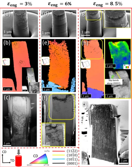
Fig.6givesanoverviewofthestrain-dependentmicrostructural developmentunderc-axiscompression.ThetoprowpresentsSEM imagesofmicropillarscompressedtodifferentstrainvaluesof3%, 6% and8.5% (see Figs.6a, 6d and6g).The imagesindicatelarger slipoffsetsatthepillarsurfacetooccurwithincreasingdeforma- tionstrain,associatedwithaprogressiveincreaseinthenetbasal shearaccumulation.Thecorresponding t-EBSDmaps,displayedin inversepole-figurecolorcodinginthemiddlerow(seeFigs.6b,6e and6h), reveal theabsence oftwinning inthepillars, suggesting the plasticitytobe bornesolelyby dislocation slip. Thecompari- sonofthealignmentofthec-axisuponincreasingthestrainfrom 3%to8.5%revealsagradualrotationofthebasalplanesawayfrom thecompressionplane.TheinsetimagesinFig.6b,corresponding toIQt-EBSDdataandabright-fieldTEMmicrograph,revealsimul- taneous basal,prismatic andpyramidal II
c+a slip. At a strainof 8.5%, the IQ map (Fig.6h) reveals sharp slipbands along the primatic planes, andthe corresponding KAM data (Fig. 6h) indi- cates significantstress build-upalong theslip bands.Thebottom rowpresentsTEMmicrographsoftheentirepillarfortheselected deformation strains. At 3% strain (Fig. 6c) the dislocation activity appears to be primarily confined to the lower half of the pillar andtothetop corners.Asthe strainincreasesto6% (Fig.6f), the
dislocationactivityextendsto thetophalfofthepillar,described by dislocation tracesalong basal and non-basal planes.A further strain increment gives rise to a more complex dislocation struc- ture(Fig.6i)acrosstheentirepillarwiththeactivationofmultiple slipmodesthatmaymutuallyinteract.
3.4. Defectanalysisusingtransmissionelectronmicroscopy
An in-depthlocal-scale analysisof thedislocations anddefect structures is realized by TEM. Figs. 7a and7b show TEMmicro- graphsofthemicropillardeformedunderc-axisextensionupto a strain of 6.5%, revealing the structure of the twinned grain and the remaining parent. The beam direction for the twinned area wasparallelto
10¯10.Atwo-beamconditionwasestablishedfor the twinned grain with diffraction vectorsg1= (0002) andg2= (11¯20)(see Fig. 7a). The light grey arrows indicate the directions oftheoperatingdiffractionvector.Foreach diffractionvector, the imageswereacquiredunderweak-beamdark-field(WBDF)condi- tions,complyingtoag·(3g)diffraction.Fig.7arevealsalargeden- sityof(0002)defectstraversingacrossthepillar width(indicated by white arrow heads) and appear as straight, narrow streaks.Thespeckleddiffractioncontrastalong thesesharpplanar streaks in Fig. 7a most likely indicates that these are I2-type ‘deforma- tion’faults that are alignedinan edge-onview, presumablycre- atedbytheglideofShockley-typepartials,i.e.(13
10¯10+1301¯10)duringplasticdeformation. Inbetweenthestacking-fault likede- fects, there exists a large density of
c dislocation segments ly- ingonthenon-basalpyramidalIIplanes(shownbyredarrowsin Fig. 7a). Imaging of the same region under g2= (11¯20) reveals onlyadislocationsegments basedupontheg·b invisibilitycri- terion,thereby confirmingthat the dislocationsonthe pyramidal planespossessac+aBurgersvector.Fig. 7c presents the initial parent grain with an operating diffractionvectorg=(0002).Theimageonceagainrevealsdisloca- tionsegmentsthathavea
c+a-typeBurgersvectoronpyramidalIIglideplanesinthevicinityofthetwin-parentinterface.Theinset image (Fig.7d)presentsa zoomed-inview ofthetwinboundary, revealinghalf-dislocationloopspinnedtothetwinboundary,with the dislocation linebowing out intothe parent grain,which is a typicalfeatureofaFrank–Readsource.Suchsourcescanpotentially giverisetodynamicdislocationnucleationduringdeformation.
Fig. 6. (a, d, g) SEM images of ZX10 micropillars deformed to (a) 3%, (d) 6% and (g) 8.5% engineering strain under c-axis compression . (b, e, h) Inverse pole figure orientation maps and crystallographic orientation of the micropillar with increasing strain values, corresponding to (b) 3%, (e) 6.5% and (h) 10% strain. In (h) a KAM map and IQ map, illustrating local strain concentrations along the prismatic planes, are additionally shown. (c, f, i) TEM micrographs of the micropillars at (c) 3%, (f) 6% and (i) 8.5% engineering strain. Basal- a slip traces are depicted in black, {10 ¯1 0 } prismatic a slip traces are shown in yellow,and {11 ¯2 2 } pyramidal c + a slip traces are shown in red lines.The legend indicates the loading mode with respect to the pillar orientation and starting grain orientation.
Inordertoconfirmthepresenceofstackingfaults,thelamella wastiltedfurther untiltheedge-onfaultsappeared asbrightand dark fringes as shown by the white arrow heads in the BF-TEM image in Fig. 8a. The operating diffractionvector corresponds to g=(10¯11). Thefaint contrastof theShockleypartial dislocations is denoted by the thick black arrows. A large number of curved
c+a dislocations are additionally observed to interact withthe stacking faults (denoted by red arrow heads in Fig. 8a). Fig. 8b shows aschematic illustrationofthe TEMimage in Fig.8a, with the thick blackarrowsshowingtheboundingpartial dislocations.The red curvedlines in Fig. 8bcorrespond to pyramidal disloca- tions.Fig.8cshowsaTEMimagesimulationperformedforabasal stacking faultobservedundersimilar imagingconditionsasthose inFig.8a.Afoilnormalcorrespondingto
10¯10waschosen,withthebeamdirectioncloseto
7¯2¯53.Theoperatingdiffractionvec- tor waschosen as (10¯11).The leadingandtrailing Shockleypar-tialsweredefinedbytheBurgersvector 13
10¯10and 1301¯10,re-spectively. Thefault-planenormal correspondedto
0002, andalamella thickness of 250nm waschosen for the simulation. The goodagreement betweentheexperimental andsimulatedimages suggeststhat the observed planardefects are indeedI2-type ‘de- formation’faults.
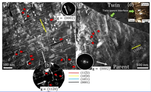
Fig.9presentsTEMmicrographsofamicropillardeformedun- der c-axis compression to a strain of 6%. Figs. 9a-c are imaged with an operating diffraction vector g1= (0002), where Fig. 9c isacquiredunderWBDFdiffractionconditions(g·(3g)).Similarto the twinnedgrain in Fig.7a, thepillar comprises a largedensity of(0002) stacking faults withpyramidalII
c+a dislocation seg- ments.Fig.9dshowsabright-field(BF)imageofthesameareaas inFig.9c.The diffractioncontrastrevealssmallprismaticdisloca- tionloopsvisibleattheintersectionzonesofthenon-basal dislo- cationsegmentsandI2-typebasalstackingfaults.I. Basu, M. Chen, J. Wheeler et al. Acta Materialia 211 (2021) 116877
Fig. 7. (a, b) WBDF images of the twinned crystal, deformed to 6.5% strain under c-axis extension , for (a) (0 0 02 ) and (b) (11 ¯2 0 ) diffraction vectors. (c) WBDF image of the un-twinned parent grain for a (0 0 02 ) diffraction vector. (d) Inset showing pyramidal dislocation half-loops forming at the twin-parent interface, marked by white arrows.
Basal a slip traces are depicted by black lines, {10 ¯1 0 } prismatic a slip traces are shown in yellow lines,and {11 ¯2 2 }pyramidal c + a slip traces are shown by red arrows.
The white arrow heads highlight basal stacking faults.
Fig. 8.. (a) Fringe contrast of basal stacking faults visible by further tilting. The diffraction vector corresponds to (10 ¯1 1 ) and red arrow heads highlight c + a dislocations.
(b) Schematic illustration of the observed stacking-fault morphology and spatial arrangement of the binding Shockley partials. (c) TEM image simulations performed under the same imaging conditions, illustrating the presence of I 2-type ‘deformation’ faults.
4. Discussion
4.1. Twinningcharacteristicsduringc-axisextension:ZX10versus pureMg
The loadingoftheZX10micropillarsnormaltotheirc-axisre- sulted in acombination oftwinning anddislocation slip-induced plasticityresponse.Pillardeformationthatproceededbymeansof
{
10¯12}
tensiontwinningresultedinacharacteristic86°rotationof the c-axisand alignedit nearly parallel to the compression axis.Theoretically, a given orientation when compressed perpendicu-
lartoits c-axiscan potentially twinalongsixcrystallographically equivalent
{
10¯12}
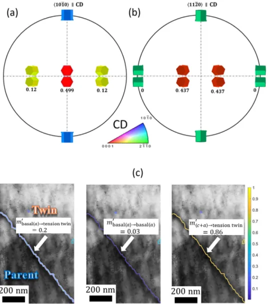
planes [42]. However, in practical cases onlythose twinorientationswhose resolved shearstress on thehabit planeinthetwinningshear directionexceedsa criticalvalue will nucleate,i.e. those possesingthe highestSchmid factor (mglobal), asillustrated inFigs. 10a and10b. In the presentcase, thetwin orientationnucleatingat3%deformationstraincorrespondstothe highestSchmid-factorvariant,asindicatedinFig.10a.
Subsequent straining to 6.5%, however, promoted additional twinningeventsintheformofnano-scale twinsappearingatthe twin-parent interface (Figs. 4e and 4f), complying with the low
Fig. 9. (a, b) DF TEM images of the micropillar at different magnifications for (0 0 02 ) diffraction. Correlative (c) WBDF and (d) BF images of a representative re- gion in the micropillar deformed to 6% engineering strain under c-axis compression.
Basal a slip traces are depicted by black lineand {11 ¯2 2 } pyramidal c + a slip traces are shown by red arrows (9b, 9c and 9d) and a red line (9a).
Schmid-factortwinvariants.Thesetwinvariantstheoreticallycor- respondto aSchmidfactorof0.12 asopposedtothered-colored primarytwinvariantthathasaSchmidfactorof0.499.Such‘non- Schmid’ twinning response stems fromthe dominantrole of lo- cal stress heterogeneities or strain-accommodation requirements near pre-existing defect structures, such as grain boundaries. In this regard, a critical factor that influences the aforementioned Schmid rule for twin-variant selection in hexagonal materials is the ease ofaccommodation ofassociated twinning shear via slip ortwinningintheneighboringgrain.Inordertoassesssuchlocal strain-accommodationeffectsontwinnucleation,theroleofgrain- boundarycrystallographyintermsofstraintransmissionneedsto be evaluated. In the case of metallic materials the feasibility of strain transmissionacross grain boundaries isdetermined by the geometricalignmentoftheactiveslip/twinningsystemsacrossthe interface and the minimization of the dislocation energy at the boundary[41,43-45].Mathematically,itcanbedescribedbyalocal Schmid-factorparameter,mlocal,givenas
mlocal=
(
n1·n2) (
b1·b2)
, (1)wheren1andn2arethenormalizedintersectionlinescommonto the slip/twin planes andboundary plane, and b1 andb2 are the normalizedtwinningshear/slipdirectionsinthepile-upandemis- sion grains. Larger values of mlocal indicate well aligned incom- ing and outgoing deformation modes across the grain boundary, andthereforeeasierstraintransmission.Potentialtwinvariants,for whichtheactiveslipsystemsintheadjacentgrainareabletoeas-
Schmid twinning eventis unlikely, asrevealed by the low mlocal valuesforsuch acase. Moreover, low mlocal values in thecase of basalslipasthesoledeformationmodeinboththetwinandpar- ent grainsemphasizeupon the role oftwin boundariesinacting asstrongbarriersagainstthemotionofbasaldislocationsandthus giverisetostresspile-upattheinterface.Thisaspectwithrespect toslipdynamicsisdiscussedingreaterdetailinSection4.3.
At even higher strains (≥10%), twinning extends across the whole pillar, giving rise to a transition into dislocation-slip me- diatedplasticity.The simultaneousactivityofbasalandnon-basal slipgives riseto complexdislocation-twin boundaryinteractions, where the local stress fields facilitate nucleation of
{
10¯11}
com-pression twins at the twin-parentinterface. Additionally, the ap- pearance of
{
10¯12}
nano-twins inside the already twinned grainsare also observed.Nucleation of such second-generationtwins is possibleduetosufficientnon-basalslipactivityinsidethetwinned grains,whichrealignthec-axisawayfromtheCDandenablesuch secondarytwinningevents.
In comparison, the twinning characteristics in pure Mg indi- catedstrong variantselection resulting in theappearance of two twin variants in the deformed Mg micropillar. On comparison with the possible twin orientations (shown in Fig. 10), the two twinvariants correspond to orientations closeto the orange-red, highSchmid-factorvariantsthattypicallyoriginatefromthegreen
11¯20 || CD parent (see Fig. 10b). EBSD analysis on the originalorientation of the pure Mgpillar indicates that the parent grain deviatedby~ 10-15°fromtheideal
10¯10||CDorientation(see SupplementaryFig.4).SEMinvestigationsontheparentgrainalso indicatetracesofprismaticaslip(seeFig.1).Itisthusproposedthatthesimultaneousactivityofprismaticslipalongwithprimary tensiontwinningintheparentgrainpromotesrotationtowardsthe morestable
11¯20||CDorientation,thereby explainingthepres- enceof two high Schmid-factortwin variants. Subsequent defor- mationinsidethetwinsproceedsviaprofusebasalslip.4.2. EffectofZnandCasolutesontwinningstresses:Nucleationand growth
Thestressvaluesatwhichthetwinsnucleateandgrowduring the onsetof
{
10¯12}
twinning deformation are estimated fromthe loadingcurvesshowninFig.1,whichhighlightthetwinnucleation andgrowtheventsbygreenandbluearrows,respectively.Fig.11a comparesthestress-strainbehaviorcorrespondingtothetwinning onset in ZX10 with that of pure Mg. The observed stress peak prior to the sharpstress drop at around 1.9%strain isattributed tothestress requiredtogenerateastabletwinnucleusbound by{
10¯12}
10¯11 twinning partials, and the subsequent short stressplateaucorrespondstothetwin-growthregime.Theappearanceof thestressplateaurelatestoanatomic-shufflingdominatedlateral
I. Basu, M. Chen, J. Wheeler et al. Acta Materialia 211 (2021) 116877
Fig. 10. Crystallographically possible high and low Schmid-factor twin-variant orientations with respect to parent orientations: (a) 10 ¯1 0 || CD and (b) 11 ¯2 0 || CD. (c) Local Schmid factors ( m local) or strain transmission analysis corresponding to basal a slip –{10 ¯1 2 } tension twinning, basal a – basal a slip, and pyramidal II c + a slip –{10 ¯1 2 }tension twinning.
twin-growth mechanism, whichis known to proceed withnegli- gibleshear[46].Fig.11bshowsthe
{
10¯12}
tension-twinnucleation andgrowthstresses,whichcorrespondtothepeak stressandthe plateaustressvaluesaveragedover3independentflowcurves,re- spectively.Whilethetwin-growthstressesaresimilarforbothma- terials (∼ 176 − − 178MPa), the twin-nucleationstress showsa clearincrementincaseofZX10(τ
reltwin∼ 29MPa)ascompared to pureMg(at∼ 198 MPa). Thisclearlyillustratesthe benefitof ZnandCasolutesinstrengtheningthetwinningresponseofMg.In order to clearlycorrelate the influence ofsolutes on twin- ning, it is important to investigate the associated atomistic pro- cessesthatareatplayduringtwinnucleationinhexagonalmetals andalloys.Despitethefactthattheexactmechanisticsoftwinnu- cleationare atopicofdebate,therehavebeenseveraltheoretical andmodellingeffortstopredictthepossiblepathwaysoftwinfor- mation [8,9,47,48].Based uponenergeticconsiderationsandcom- parisons with experimentally measured twin-boundary energies, the generallyagreedmechanismoftwinformationis theone in- volvingzonaldislocations,alsoreferredtoaszonal-twinningmech- anism[47,49,50].
Mathematically [47], the formation of a twinning partial, de- scribedbyitsBurgersvector’btw→’,onthe
{
10¯12}
twinningplanealongthe
10¯11sheardirectionisgivenbybn←+bp→=btw→ (2)
wherebn←andbp→correspondtotheBurgersvectoroftherespec- tive partial dislocationswith opposite signs that account for the displacements neededfor
{
10¯12}
planes to changetheir stackingtype, withtheir magnitudesgiven as
|
bn←|
= √γ23+γ2and
|
bp→|
=√3
3+γ2, and
γ
=|
c/a|
. The magnitude of btw→can be expressed as|
btw→|
=|
bp→|
−|
bn←|
= √3−γ23+γ2andpossessesanoppositesign withrespect tobn←. Withrespect tothe zonal-twinning mecha- nism,twinnucleationinvolvestheformationofzonaldislocations, which simultaneously comprise the glide of bn←along the twin- parent interface and the atomic shuffling associated with shear, which is induced by multiple twinning partials btw→that glide on adjacent
{
10¯12}
planes inside the twinned nucleus. The netBurgers vector of a zonal dislocation is then defined as bzonal= bn←+
κ
btw→,whereκ
istheminimumintegersuchthatbzonal>Fig. 11. (a) Characteristic stress-strain response associated with twin nucleation and twin growth in pure Mg (empty blue cricles) and ZX10 (filled blue circles).
(b) Experimentally measured averaged twin-nucleation and twin-growth stresses for both materials.
0for
γ
<√3.Thecorrespondingminimumthicknessofatwinnu- cleus stableenough totransitionintogrowthisgivenby(2
κ
+1){
10¯12}
planes.In thepresenceofa solute environment,dislocation glidewill experienceresistanceresultingfromitsinteractionwiththesolute atoms. The nature of this interaction is a combinationof elastic effects i.e.the solute and dislocation stress fieldsmutually inter- act, andachemical contributionorSuzukieffectthatresultsfrom changing the interatomic bonding environment due to segrega- tion ofsolutesinsidedislocation coresandstacking faults[51,52].
Mechanistically, thedislocationlinetraversinginafieldofsolutes willadoptawavycharactersuchthatitstatisticallyfindsfavorable regions ofsolute fluctuations, thereby lowering the potential en- ergy.However,thebowingofthedislocationlineoccursatthecost ofadditionalelasticlineenergycomparedtoanotherwisestraight dislocationsegment.Thisadditionalstresscomponentaccountsfor dislocationstrengthening[53].
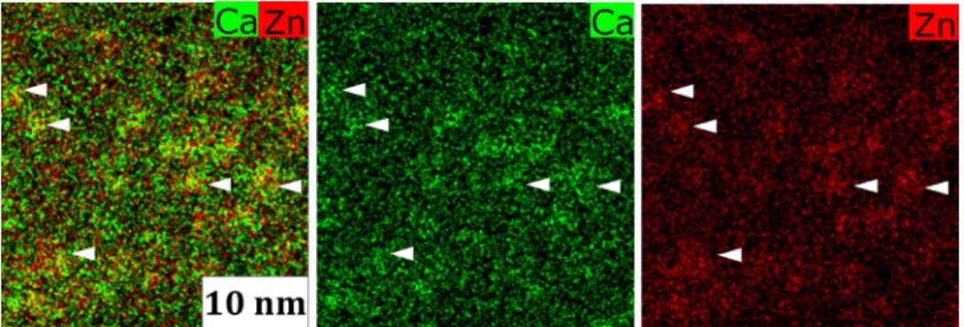
Considering the sizable strength increment for twinning in ZX10 despite the leanness of its alloying content, conventional solid-solutionstrengtheningcannotbeseenasthesoleresponsible strengthening mechanism,asisthe casefora randomsolid solu- tion.ComparingtheatomicradiiofZn(134 pm)andCa(197pm) withthatofMg(160pm),itcanbeconcludedthattheatomicsize misfits generatedby thesoluteswillgive risetotensileandcom- pressivestress fields,respectively. Fromtheperspective ofchemi- calaffinities,thebindingenergies(E)forMg–Ca,Mg–ZnandZn–
Ca pairsare−6kJmol−1,−4kJmol−1 and−22kJmol−1,respec- tively[54,55].Thehighlynegativevaluesindicateastrongpropen- sityofheterogeneousZn–Cabond-pairformationintheZX10alloy
τ
SRO=γ
SRO|
b|
≈fcluster
(
ESRO−Erandom)
|
b|
3 (3)where,
γ
SRO isthe energy change associated with destroying the locallyorderedconfiguration perunit area,ESRO istheshort-range orderingenergy,Erandom istheenergystateofarandomsolid so- lution,and fclusteristheoverallvolume fractionoftheco-clusters The latter can be assumed to be of a similar magnitude as the sumofthetotalatomicfractionofZnandCasolutesinMg,which amountsto around0.7%(experimentallymeasured bulkcomposi- tion:Ca ~ 0.18 at.%, Zn ~ 0.54 at.%).Furthermore,|
b|
corresponds to the magnitude of the Burgers vector of the active dislocation slipsystem, whichisinthiscase(0001)11¯20basal slip.Forthesakeofsimplicity,wereasonablyassumethat Erandom≈EMg−Mg. Thisresultsfromthelean-alloyingapproachwherethenumberof Mg–MgbondsbyfarexceedsthatoftheMg–CaandMg–Znbonds inthematrix,suchthatthecontributionoftheMg–solute-element bondingtothetotalenergyofthesystemcanbeneglectedinthe current scenario. Moreover, in the caseof co-segregation of Zn–
Ca solute clusterstheorderingenergy canbe mathematicallyex- pressedasESRO= EZn−Ca.
Inserting the values of EZn−Ca and EMg−Mg from Refs.
[26,54,58]into eqn. 3givesthe strength incrementduetoshort- rangeordering,
τ
SROZnCa≈27MPa.Interestinglythetheoretically calculatedvalue ofτ
SROZnCais inverygoodagreementwiththe observed twinstrengthening (τ
reltwin∼ 29 MPa) in ZX10(see Fig.11),therebyimplyingthatsuchchemicallydrivenlocalatomic rearrangement of solutes can play a significant role in terms of local-scalestrengthening ofzonal dislocation motionduringtwin nucleation. This results in relatively higher twinning stresses for theleanalloyZX10comparedtopureMg.Intheforthcomingsec- tions,theimpactofshort-rangeorderingonthespatialconfigura- tionanddensityofthedefectswill beelucidated, whichleadsto asignificantimprovementintheoverallmaterialstrength-ductility response.4.3. Dislocationdynamicsandslipcharacteristics
Fig.13showsananalysisofthediscretestress-dropevents,cor- respondingtoindependentdislocationbursts,detectedduringthe mechanicaltests on ZX10compared to those performed onpure Mgunderc-axiscompression.Fig.13ashowsthenumberfrequency ofdislocation-bursteventsasafunctionofstress-dropmagnitude (averagedover three stress-straincurves foreach material), indi- catinga bimodal distribution for ZX10(shown by the two peaks ashighlightedbyarrowsinFig.13a). Moreover,theappearanceof ashoulderbetweentwopeaksinthecumulative frequencydistri- bution forthe ZX10alloy (which issignificantly lesspronounced forpure Mg)relatestotheoverlapoftwounimodalpeaks,which
I. Basu, M. Chen, J. Wheeler et al. Acta Materialia 211 (2021) 116877
Fig. 12. STEM-EDS chemical maps of the Zn and Ca distributions in the bulk ZX10 alloy.
Fig. 13. Dislocation-burst event analysis under c -axis compression in terms of (a) cumulative and relative frequency of the number fraction of dislocation bursts as a function of stress-drop magnitude and (b) variation of stress-drop magnitude as a function of applied strain . The two regimes indicated by the solid red and dashed black double-arrows describe slip contributions from pyramidal II c + a slip and basal a slip, respectively .
confirmsbimodalityintheslipeventsfortheZX10alloy.Thesec- ond feature evident fromthe stress-drop distribution forZX10is thepresenceofahigh-frequencypeakwithalowstress-dropmag- nitude andthe simultaneousappearanceofa low-frequencypeak with a larger stress-drop magnitude. The aforementioned trends for ZX10 indicate simultaneous activation of basal
a and pyra-midal
c+a slipinside the micropillars,and thereforealso agree withthefindingsfromt-EBSDandTEMcharacterization.TEMob- servationsinFig.9indicatedadensenetworkofc+adislocation segments that are primarily confined in-between periodically ar-ranged basal dislocationsandstacking faults spanningacross the pillarwidth.Whenconsideringthemeanfreepathsfordislocation motion,theTEMresultsindicatesignificantlyshorterdistancestra- versedbythe
c+adislocationsbutahigherdislocationdensityas opposedtobasaldislocations,whichhavemuchlowerspatialden- sitybutlargermeanfreepaths.Sincetheplasticshear(δ
)duetoadislocation-burstevent(physicallyobservedasastress-dropevent duringdeformation)isproportionaltothedistance(x)traversedby eachdislocation(
δ
∝x)[59],thesmallermeanfreepathsforc+adislocationsmuststatisticallycorrespond tothepeakswithlower stress-dropmagnitude,whereasthestresspeakswithhighermag- nitude and relatively lower number of occurrences comply with basaldislocations.Conversely,inthecaseofc-axiscompressionof pure Mg, theunimodaldistribution correlateswiththe activation ofpredominantlyoccurringbasal
aslip,asevidentfrommassivebasalsliding,whichaccountsforthedrasticsofteningobservedin thestress-strainresponse.
Fig. 13b shows the number and distribution of dislocation events(averagedoverthreeindependentload-displacementcurves for each case) as a function of deformation strain for ZX10 and pureMg.Thefigurerevealsmuchmoredislocation-bursteventsfor ZX10(317independentdislocationbursts)thanforpureMg(92in- dependent dislocation events). Furthermore, the dislocation-burst eventsinZX10aremorehomogeneouslydistributedwithincreas- ing strainandalternate betweenintervalsofsmallstress fluctua- tions,corresponding to
c+a slip,andsingularinstances oflargestress drops,whichare associatedwithbasal
a slip. Thehomo-geneousactivationof
c+apyramidalslipandbasalaslipgivesriseto morethan fiveindependent deformation modes, andthus to uniform strain hardening andplasticity asseen in the stress- straincurveunderc-axiscompression.Thisalsoexplainsthemore gradual orientationchange ofthepillarunderc-axiscompression (seeFig.6),wheretheslip-inducedrotationsassociatedwithbasal andnon-basalsliphaveoppositesigns,sothatthenetorientation changeunderdeformationremainssmall.
Onthe other hand,thedislocation bursts inpure Mgare dis- tributed heterogeneously withincreasing strain without anydef- inite pattern of stress drops unlike for ZX10 (see Fig. 13b). The smallernumberofslip eventsandtheirnon-uniform distribution typically highlight the anisotropy inthe deformation of pure Mg andthelackofavailabledeformation modestoaccommodate the imposedplasticstrain.Thisalsoexplainstheobservedpillarinsta- bilityforpureMgatstrainslargerthan5%.
Onthe basis ofthe aforementioned dislocation dynamics, the cyclichardening andsoftening seen inthestress-strain curvesof ZX10underc-axis extensionisexplained asfollows:Plasticity be- ginswithpredominantdeformationtwinningandconcurrentpris- matic
aslipintheuntwinnedparent.Astwinningexhausts,thereorientation of the twinned crystal aligns the c-axis along the compressiondirection. This leadstoa rapidstress incrementun-