1. OSI
1.1. ISO Reference Model
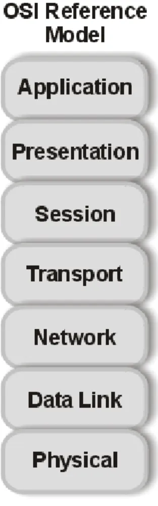
In 1983, the International Standards Organization (ISO) created the OSI, or X.200, model. It is a multilayered model for facilitating the transfer of information on a network. The OSI model is made up of seven layers, with each layer providing a distinct network service. By segmenting the tasks that each layer performs, it is possible to change one of the layers with little or no impact on the others. For example, you can now change your network configuration without having to change your application or your presentation layer. The basic OSI model is depicted in Figure 1.1.
Figure 1.1 OSI Model
The OSI model was specifically made for connecting open systems. These systems are designed to be open for communication with almost any other system. The model was made to break down each functional layer so that overall design complexity could be lessened. The model was constructed with several precepts in mind:
1) Each layer performs a separate function;
2) The model and its levels should be internationally portable; and
3) The number of layers should be architecturally needed, but not unwieldy.
1. OSI
1.2. The layers
The application, presentation, and session layers are all application-oriented in that they are responsible for presenting the application interface to the user. All three are independent of the layers below them and are totally oblivious to the means by which data gets to the application. These three layers are called the upper layers.
The lower four layers deal with the transmission of data, covering the packaging, routing, verification, and transmission of each data group. The lower layers don't worry about the type of data they receive or send to the application, but deal simply with the task of sending it. They don't differentiate between the different applications in any way.
The following sections explain each layer to help you understand the architecture of the OSI - Reference Model (and later contrast it with the architecture of TCP/IP).
The Application Layer
The application layer is the end-user interface to the OSI system. It is where the applications, such as electronic mail, USENET news readers, or database display modules, reside. The application layer's task is to display received information and send the user's new data to the lower layers.
In distributed applications, such as client/server systems, the application layer is where the client application resides.
It communicates through the lower layers to the server.
The Presentation Layer
The presentation layer's task is to isolate the lower layers from the application's data format. It converts the data from the application into a common format, often called the canonical representation. The presentation layer processes machine-dependent data from the application layer into a machine-independent format for the lower layers.
The presentation layer is where file formats and even character formats (ASCII and EBCDIC, for example) are lost.
The conversion from the application data format takes place through a "common network programming language" (as it is called in the OSI Reference Model documents) that has a structured format.
The presentation layer does the reverse for incoming data. It is converted from the common format into application- specific formats, based on the type of application the machine has instructions for. If the data comes in without reformatting instructions, the information might not be assembled in the correct manner for the user's application.
The Session Layer
The session layer organizes and synchronizes the exchange of data between application processes. It works with the application layer to provide simple data sets called synchronization points that let an application know how the transmission and reception of data are progressing. In simplified terms, the session layer can be thought of as a timing and flow control layer.
The session layer is involved in coordinating communications between different applications, letting each know the status of the other. An error in one application (whether on the same machine or across the country) is handled by the session layer to let the receiving application know that the error has occurred. The session layer can
resynchronize applications that are currently connected to each other. This can be necessary when communications are temporarily interrupted, or when an error has occurred that results in loss of data.
The Transport Layer
The transport layer, as its name suggests, is designed to provide the transparent transfer of data from a source end open system to a destination end open system, according to the OSI Reference Model. The transport layer
establishes, maintains, and terminates communications between two machines.
The transport layer is responsible for ensuring that data sent matches the data received. This verification role is important in ensuring that data is correctly sent, with a resend if an error was detected. The transport layer manages the sending of data, determining its order and its priority.
The Network Layer
The network layer provides the physical routing of the data, determining the path between the machines. The
network layer handles all these routing issues, relieving the higher layers from this issue.
The network layer examines the network topology to determine the best route to send a message, as well as figuring out relay systems. It is the only network layer that sends a message from source to target machine, managing other chunks of data that pass through the system on their way to another machine.
The Data Link Layer
The data link layer, according to the OSI reference paper, "provides for the control of the physical layer, and detects and possibly corrects errors that can occur." In practicality, the data link layer is responsible for correcting
transmission errors induced during transmission (as opposed to errors in the application data itself, which are handled in the transport layer).
The data link layer is usually concerned with signal interference on the physical transmission media, whether
through copper wire, fiber optic cable, or microwave. Interference is common, resulting from many sources, including cosmic rays and stray magnetic interference from other sources.
The Physical Layer
The physical layer is the lowest layer of the OSI model and deals with the mechanical, electrical, functional, and procedural means required for transmission of data, according to the OSI definition. This is really the wiring or other transmission form.
When the OSI model was being developed, a lot of concern dealt with the lower two layers, because they are, in most cases, inseparable. The real world treats the data link layer and the physical layer as one combined layer, but the formal OSI definition stipulates different purposes for each. (TCP/IP includes the data link and physical layers as one layer, recognizing that the division is more academic than practical.)
2. IEEE 802.3
2.1. Specifications
Ethernet is the most popular physical layer LAN technology in use today. Other LAN types include Token Ring, Fast Ethernet, Fiber Distributed Data Interface (FDDI), Asynchronous Transfer Mode (ATM) and LocalTalk. Ethernet is popular because it strikes a good balance between speed, cost and ease of installation. These benefits, combined with wide acceptance in the computer marketplace and the ability to support virtually all popular network protocols, make Ethernet an ideal networking technology for most computer users today. The Institute for Electrical and Electronic Engineers (IEEE) defines the Ethernet standard as IEEE Standard 802.3. This standard defines rules for configuring an Ethernet network as well as specifying how elements in an Ethernet network interact with one another. By adhering to the IEEE standard, network equipment and network protocols can communicate efficiently.
The first IEEE 802.3 CSMA/CD recommendation, 10Base-T, was issued in 1985. Since then, users demands have changed. The original rate of 10M bps is proving inadequate, and bit rates of 100M bps and higher are being demanded. At the same time, the industry wishes to keep as much of the old standards as possible and to ensure backwards compatibility. Thus, the media access control (MAC) and higher layers are left unchanged. Continued use of installed cables is desirable. Several fast 802.3 standards have been proposed, referred to as 100Base-T4, 100Base-X, 100Base-TX, however none has been approved.
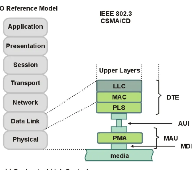
The IEEE 802.3 CSMA/CD recommendation covers the lowest two layers of the OSI reference model and comprises the media access control layer frame format, physical layer, and media specification. It also includes the media access control-physical layer interface and the medial access control-logical link control protocol interface. Together, the logical link control and media access control sublayer correspond to the OSI data link layer. The IEEE 802.3 domain is shown in Figure 2.1.
Figure 2.1 IEEE 802.3 Service Specifications
The interface between the logical link control and media access control layers is comparable to the LAP-B service request specification. It supports facilities required to transmit and receive frames, relay frame-processing
parameters, and provide error and status information on an operation-by-operation basis to the network (and higher) layers.
IEEE 802.3 recommends a generic media access control frame format for use in data transmit and receive tasks. All frames are preceded by a preamble.
The media access control frame structure is flexible enough to accommodate baseband and broadband
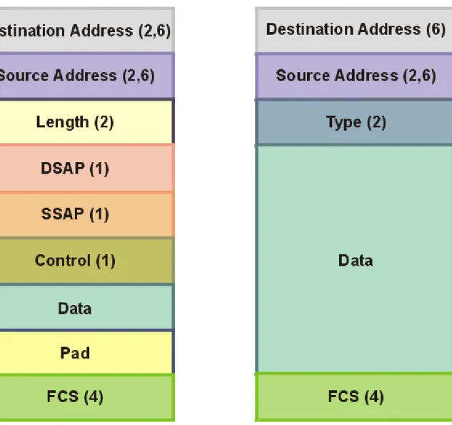
implementations. Both baseband and broadband implementations require addition of a preamble to the frame during transmission. In the broadband implementation, the frame is encapsulated with a preamble and postamble. The following various frame fields defined in IEEE 802.3 are shown in Figure 2.2.
Figure 2.2 Frame Format for IEEE 802.3 Standard
• Baseband preamble. A 56-bit pattern used by the physical layer signaling circuitry to establish bit synchronization and identify the first bit of the frame.
• Broadband preamble. The length of the preamble is 45 bits. The first 20 bits are used by the recipient to establish synchronization. These synch bits are followed by a 2-bit unscramble mode delimiter field. The final 23 bits of the preamble constitute the seed.
• Broadband postamble. The postamble is a 23-bit pattern that follows the last bit of the frame check sequence and functions as the broadband end-of-frame delimiter.
• Start frame delimiter (SFD). This 8-bit 01111110 sequence indicates the start of a frame.
• Destination address (DA). This identifies the stations that are to receive the frame. The bit pattern indicates either a unique physical address, a multicast-group address, or a global address. The choice of a 2- or 6-octet address is an implementation decision and must be the same at any given time for all stations on a particular LAN.
• The source address (SA). This specifies the station that sent the frame. The size of this field must be the same as that of the DA field.
• Length. A 16-bit field that specifies the number of logical link control bytes that follow in the data field.
• The logical link control data. This field is prepared at the logical link control level, and its size must be in octet units.
• Pad field. Added if necessary; a sequence of bits is added o the logical link control data field to ensure that the frame is long enough for proper collision detection operation. The minimum and maximum sizes for the data field are a function of the maximum frame size and address size definitions for a given implementation.
• The frame check sequence (FCS). Contains a 32-bit cyclic redundancy check value. This value is calculated based on the contents of all fields up to but not including the FCS.
The IEEE 802.3 standard specifies a CMSA/CD media access control operation at the media access control sublayer. On receiving a request for transmission, the transmit data encapsulation component constructs a protocol data unit frame using logical link control data. The transmit media access management samples the communication channel. When the medium becomes clear, transmission begins and the logical link control is informed. In the case of a collision, the transmit media access management transmits a jam signal to ensure that all transmitting stations have detected the collision. The transmission is terminated and retry begins after a back-off interval.
When a station enters the data receive mode, the physical layer signaling interface detects an incoming frame and discards the leading synch bits, the preamble, and the start frame delimiter. The physical layer signaling then forwards the data to the receive data decapsulation component. This process continues until the carrier-sense signal goes off. Then, the receive data decapsulation component evaluates the destination address and checks the data for transmission errors. If the address is valid and data is error free, the frame is forwarded to the logical link control;
frames with invalid addresses or data transmission errors are discarded or passed to network management for further processing.
The transmit and receive media management activities are supported by the physical layer’s three components: the physical layer signaling (PLS), attachment unit interface (AUI), and physical medium attachment (PMA).
The physical layer signaling shields the media access control layer from the intricacies of establishing, maintaining, and tearing down the serial communications pipe. This interface supports transmit-receive bit streams and channel- allocation and contention-resolution tasks. The physical signaling layer uses five primitives. Those can be grouped according to their functions as shown in Figure 2.3.
Figure 2.3 Physical Signaling Layer Primitives
The attachment unit interface includes specifications for cable connectors and transmission circuitry used to interconnect the physical layer signaling and media access unit in compliance with the following characteristics:
• The AUI must be capable of driving 50 m of cable.
• The AUI must permit data terminal equipment to test the AUI, AUI cable, medium attachment unit (MAU), and medium itself.
• The AUI must support the MAU for baseband coaxial cable, broadband coaxial cable, and baseband optical fiber.
The MAU is the portion of the physical layer between the medium-dependent interface and the AUI. It links the medium to the connector cable and contains the electronic circuitry that sends, receives, and manages the encoded signals impressed on and recovered from the trunk coaxial cable.
The medium-dependent interface is the mechanical and electrical interface between the trunk cable medium and the medium attachment unit.
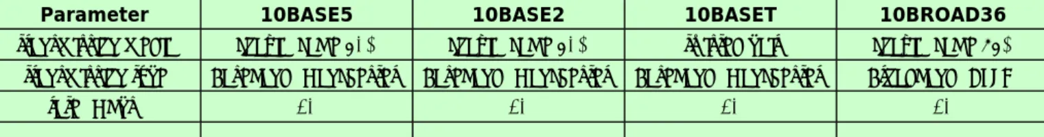
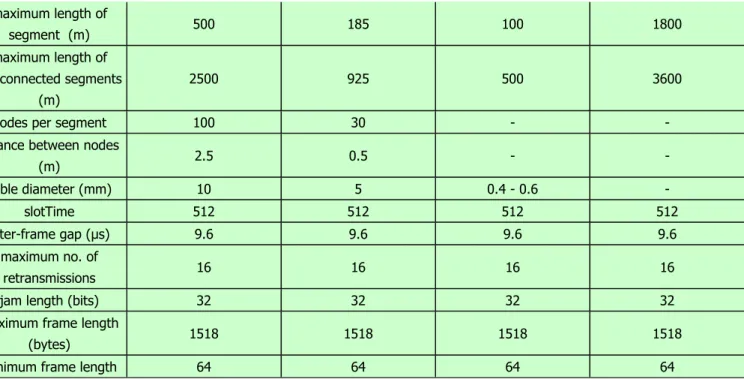
The typical specifications for IEEE 802.3 are given in Figure 2.4.
PLS_DATA.request (OUTPUT_UNIT)
PLS_DATA.confirm (OUTPUT_STATUS)
PLS_DATA.indication (INPUT_UNIT)
PLS_CARRIER.indication (CARRIER_STATUS)
PLS_SIGNAL.indication (SIGNAL_STATUS)
Parameter 10BASE5 10BASE2 10BASET 10BROAD36
transmission media coaxial cable 50Ω coaxial cable 50Ω twisted pair coaxial cable 75Ω transmission type Baseband (Manchester) Baseband (Manchester) Baseband (Manchester) Broadband (DPSK)
rate (Mbps) 10 10 10 10
Figure 2.4 Typical Specifications for IEEE 802.3
For baseband implementation the IEEE 802.3 standard uses a 10M-bps channel with a minimum frame of 512 bits.
The network can use 500-m segments for coaxial cable and 1-km segments for optical fiber. The distance between the cable tap and the station should not exceed 50 m.
IEEE 802.3 broadband CSMA/CD allows a segment length of 3.75 km; however, 5.5 km is achievable. Historically, the major technological problem was the allocation of the frequency channels. Because no standard existed for frequency allocations, applications assigned to one channel by one vendor often overlapped with the frequencies of another, causing interference or cross talk on other channels. However, by adhering to the recommendations of the 802.7 technical advisory group, frequency overlap should not pose a serious threat.
In many implementations of CSMA/CD over cable television-type cable, two separate channels are used. A node that has packets to transmit listens for transmission activity on the downlink channel. If the downlink is idle, the station transmits its packet on the uplink channel while performing collision detection handling and enforcement. If the node senses that the downlink is busy, indicating a transmission in progress, the station waits before proceeding to transmit on the uplink channel. The station performs collision detection by comparing the received downlink transmission, bit by bit, with the data transmitted on the uplink. Collision detection is concurrent with packet transmission and is usually performed for an interval known as the collision window. When a transmitting station detects a bit mismatch at any time during the window, it knows that a collision has occurred. In accordance with the CSMA/CD algorithm, the sending node first initiates a collision enforcement, then retries the channel after the back- off interval.
New trends in the topology of LANs include star topology networks, which have a hub or a switch at their center.
Most hubs are actually concentrators; future switches will use the asynchronous transfer mode (ATM). For the latter, ATM converters are required at the terminals and stations. Terminals and stations connected to a hub can use the 802.3, or other, protocols. The 802.3 standards committee has decided not to address switching as a separate issue, claiming that existing 802.3 standards can be applied.
maximum length of
segment (m) 500 185 100 1800
maximum length of interconnected segments
(m)
2500 925 500 3600
nodes per segment 100 30 - - distance between nodes
(m) 2.5 0.5 - -
cable diameter (mm) 10 5 0.4 - 0.6 -
slotTime 512 512 512 512
inter-frame gap (μs) 9.6 9.6 9.6 9.6 maximum no. of
retransmissions 16 16 16 16
jam length (bits) 32 32 32 32 maximum frame length
(bytes) 1518 1518 1518 1518
minimum frame length 64 64 64 64
2. IEEE 802.3
2.2. Implementations
Standard Ethernet (Coax): 10BASE5
z The maximum length of a segment is 500 metres.
z A maximum of 2 IRL (InterRepeater Links) is allowed between devices; the maximum length of cable is 2.5 km.
z Devices attach to the backbone via transceivers.
z The minimum distance between transceivers is 2.5 metres.
z The maximum length of a transceiver cable is 50 metres.
z Up to 100 transceiver connections can be attached to a single segment.
z Only transceivers without SQE ("heartbeat") test enabled should be used with repeaters.
z Both ends of each segment should be terminated with a 50-ohm resistor.
z One end of each segment should be grounded to earth.
ThinNet Ethernet (Coax): 10BASE2
z The maximum length of a segment is 185 metres.
z A maximum of 2 IRL (InterRepeater Links) is allowed between devices; the maximum length of cable is 925 metres.
z Typically, devices use Ethernet network interface cards (NICs) with built-in BNC transceivers, so connections can be made directly to the ThinNet cable.
z Devices are connected to the cable with T-connectors, which must be plugged directly into the card. No cable is allowed between the T and the card. Workstations are daisychained with an "in-and-out" cabling system.
z The minimum distance between T-connectors is 0.5 metres.
z If the interface card does not have its own built-in BNC transceiver, a BNC transceiver and transceiver cable are required. The maximum length of a transceiver cable is 50 metres.
z Up to 30 connections can be attached to a single segment.
z Both ends of each segment should be terminated with a 50-ohm resistor.
z One end of each segment should be grounded to earth.
Twisted-Pair Ethernet (Unshielded Twisted Pair): 10BASE-T, UTP
z There are two versions of Ethernet over unshielded twisted pair: 10BASE-T (the standard) and its predecessor UTP.
z 10BASE-T and UTP segments can coexist on the same network via a transceiver and transceiver cable or converter when each hub is attached to a common segment.
z The cable used is 22 to 26 AWG unshielded twisted pair (standard telephone wire), at least Category 2 with two twists per foot. Category 3 or 4 is preferred. Category 5 supports 100BASE-T (Fast Ethernet) and is recommended for all new installations.
z Workstations are connected to a central concentrator ("hub") in a star configuration. Concentrators can be attached to a fiber optic or coax network and can be daisychained to form larger networks.
z A hub usually also has an AUI port for standard Ethernet connections.
z The maximum segment distance from concentrator to node is 100 metres.
z The maximum number of devices per segment is two: the hub port and the 10BASE-T or UTP device.
z Ethernet network interface cards (NICs) are available with built-in 10BASE-T transceivers.
z Devices with standard AUI ports may be attached with a twisted-pair transceiver.
z Twisted pair is the most economical cable type, since it may already be installed, and it is the easiest to work with. But it's not recommended for installations with a great deal of EMI/RFI interference (for example, in industrial environments).
Fiber Optic Ethernet: FOIRL or 10BASE-FL
z There are two versions of Ethernet over fiber optic cable, one for the older FOIRL (Fiber Optic InterRepeater Link) and one for the more recent 10BASE-FL standards.
z FOIRL and 10BASE-FL fiber optic Ethernet differ only in how far each will transmit (the maximum length of a segment). For FOIRL it is 1 km; for 10BASE-FL it is 2 km.
z The maximum number of devices per segment is two: the hub port and the 10BASE-FL device.
z Fiber optic cable provides the best signal quality as well as the greatest point-to-point distance and is completely free of EMI/RFI interference.
z Fiber optic cable runs point to point only-it cannot be tapped or daisychained. A fiber optic hub or multiport repeater is required to carry the signal to multiple devices (for FOIRL, a FOIRL multiport repeater and transceivers).
Since fiber optic cable does not carry electrical charges, there are no electrical cable problems. And it's immune to electronic eavesdropping. When outdoor-quality fiber optic cable is used to link buildings, grounding problems and
voltage spikes are eliminated.
3. TCP/IP
3.1. TCP/IP and OSI
The adoption of TCP/IP didn't conflict with the OSI standards because the two developed concurrently. In some ways, TCP/IP contributed to OSI, and vice-versa. Several important differences do exist, though, which arise from the basic requirements of TCP/IP which are:
z A common set of applications z Dynamic routing
z Connectionless protocols at the networking level z Universal connectivity
z Packet-switching
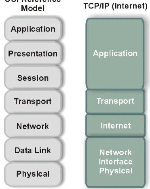
The differences between the OSI architecture and that of TCP/IP relate to the layers above the transport level and those at the network level. OSI has both the session layer and the presentation layer, whereas TCP/IP combines both into an application layer. The requirement for a connectionless protocol also required TCP/IP to combine OSI's physical layer and data link layer into a network level. TCP/IP also includes the session and presentation layers of the OSI model into TCP/IP’s application layer. A schematic view of TCP/IP's layered structure compared with OSI's seven-layer model is shown in Figure 3.1. TCP/IP calls the different network level elements subnetworks.
Figure 3.1 The OSI and TCP/IP layered structures.
Some fuss was made about the network level combination, although it soon became obvious that the argument was
academic, as most implementations of the OSI model combined the physical and link levels on an intelligent controller (such as a network card). The combination of the two layers into a single layer had one major benefit: it enabled a subnetwork to be designed that was independent of any network protocols, because TCP/IP was oblivious to the details. This enabled proprietary, self-contained networks to implement the TCP/IP protocols for connectivity outside their closed systems.
The layered approach gave rise to the name TCP/IP. The transport layer uses the Transmission Control Protocol (TCP) or one of several variants, such as the User Datagram Protocol (UDP). (There are other protocols in use, but TCP and UDP are the most common.) There is, however, only one protocol for the network level—the Internet Protocol (IP). This is what assures the system of universal connectivity, one of the primary design goals.
There is a considerable amount of pressure from the user community to abandon the OSI model (and any future communications protocols developed that conform to it) in favor of TCP/IP. The argument hinges on some obvious reasons:
z TCP/IP is up and running and has a proven record.
z TCP/IP has an established, functioning management body.
z Thousands of applications currently use TCP/IP and its well-documented application programming interfaces.
z TCP/IP is the basis for most UNIX systems, which are gaining the largest share of the operating system market (other than desktop single-user machines such as the PC and Macintosh).
z TCP/IP is vendor-independent.
Arguing rather strenuously against TCP/IP, surprisingly enough, is the US government—the very body that sponsored it in the first place. Their primary argument is that TCP/IP is not an internationally adopted standard, whereas OSI has that recognition. The Department of Defense has even begun to move its systems away from the TCP/IP protocol set. A compromise will probably result, with some aspects of OSI adopted into the still-evolving TCP/IP protocol suite.
3. TCP/IP
3.2. TCP/IP Suite
TCP/IP was designed with layers as well, although they do not correspond one-to-one with the OSI-RM layers. You can overlay the TCP/IP programs on this model to give you a rough idea of where all the TCP/IP layers reside. This chapter takes a quick look at the TCP/IP protocols and how they relate to each other, and show a rough mapping to the OSI layers.
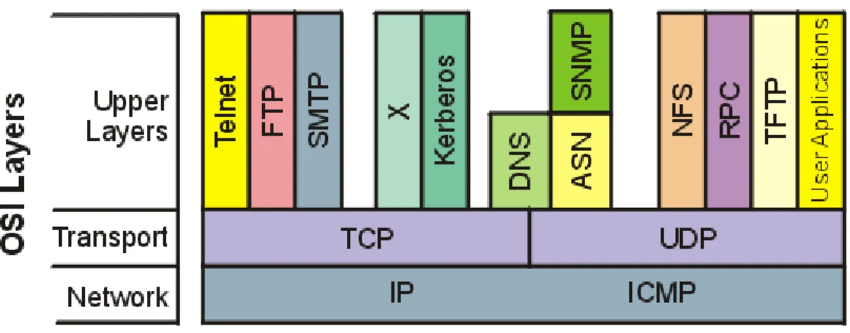
Figure 3.1 shows the basic elements of the TCP/IP family of protocols. TCP/IP is not involved in the bottom two layers of the OSI model (data link and physical) but begins in the network layer, where the Internet Protocol (IP) resides. In the transport layer, the Transmission Control Protocol (TCP) and User Datagram Protocol (UDP) are involved. Above this, the utilities and protocols that make up the rest of the TCP/IP suite are built using the TCP or UDP and IP layers for their communications system.
Figure 3.2 TCP/IP suite and OSI layers.
Figure 3.2 shows that some of the upper-layer protocols depend on TCP (such as Telnet and FTP), whereas some depend on UDP (such as TFTP and RPC). Most upper-layer TCP/IP protocols use only one of the two transport protocols (TCP or UDP), although a few, including DNS (Domain Name System) can use both.
A note of caution about TCP/IP: Despite the fact that TCP/IP is an open protocol, many companies have modified it for their own networking system. There can be incompatibilities because of these modifications, which, even though they might adhere to the official standards, might have other aspects that cause problems. Luckily, these types of changes are not rampant, but you should be careful when choosing a TCP/IP product to ensure its compatibility with existing software and hardware.
TCP/IP is dependent on the concept of clients and servers. This has nothing to do with a file server being accessed by a diskless workstation or PC. The term client/server has a simple meaning in TCP/IP: any device that initiates communications is the client, and the device that answers is the server. The server is responding to (serving) the client's requests.
3. TCP/IP
3.3. IP Addresses
TCP/IP uses a 32-bit address to identify a machine on a network and the network to which it is attached. IP addresses identify a machine's connection to the network, not the machine itself—an important distinction.
Whenever a machine's location on the network changes, the IP address must be changed, too. The IP address is the set of numbers many people see on their workstations or terminals, such as 127.40.8.72, which uniquely identifies the device.
IP (or Internet) addresses are assigned only by the Network Information Center (NIC), although if a network is not connected to the Internet, that network can determine its own numbering. For all Internet accesses, the IP address must be registered with the NIC.
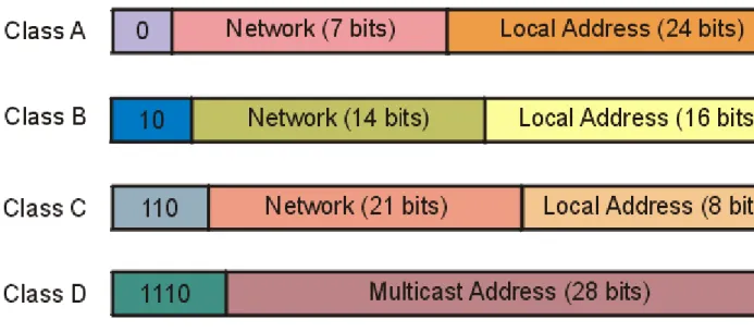
There are four formats for the IP address, with each used depending on the size of the network. The four formats, called Class A through Class D, are shown in Figure 3.3. The class is identified by the first few bit sequences, shown in the figure as one bit for Class A and up to four bits for Class D. The class can be determined from the first three (high-order) bits. In fact, in most cases, the first two bits are enough, because there are few Class D networks.
Figure 3.3 The four IP address class structures.
Class A addresses are for large networks that have many machines. The 24 bits for the local address (also
frequently called the host address) are needed in these cases. The network address is kept to 7 bits, which limits the number of networks that can be identified. Class B addresses are for intermediate networks, with 16-bit local or host addresses and 14-bit network addresses. Class C networks have only 8 bits for the local or host address, limiting the number of devices to 256. There are 21 bits for the network address. Finally, Class D networks are used for
multicasting purposes, when a general broadcast to more than one device is required. The lengths of each section of the IP address have been carefully chosen to provide maximum flexibility in assigning both network and local
addresses.
IP addresses are four sets of 8 bits, for a total 32 bits. You often represent these bits as separated by a period for convenience, so the IP address format can be thought of as network.local.local.local for Class A or
network.network.network.local for Class C. The IP addresses are usually written out in their decimal equivalents, instead of the long binary strings. This is the familiar host address number that network users are used to seeing, such as 147.10.13.28, which would indicate that the network address is 147.10 and the local or host address is 13.28. Of course, the actual address is a set of 1s and 0s. The decimal notation used for IP addresses is properly called dotted quad notation.
The IP addresses can be translated to common names and letters. This can pose a problem, though, because there must be some method of unambiguously relating the physical address, the network address, and a language-based name (such a tpci_ws_4 or bobs_machine). The section later in the next chapter titled "Domain Name System" looks at this aspect of address naming.
From the IP address, a network can determine if the data is to be sent out through a gateway. If the network address is the same as the current address (routing to a local network device, called a direct host), the gateway is avoided, but all other network addresses are routed to a gateway to leave the local network (indirect host). The gateway receiving data to be transmitted to another network must then determine the routing from the data's IP address and an internal table that provides routing information.
As mentioned, if an address is set to all 1s, the address applies to all addresses on the network. (See the previous
section titled "Physical Addresses.") The same rule applies to IP addresses, so that an IP address of 32 1s is considered a broadcast message to all networks and all devices. It is possible to broadcast to all machines in a network by altering the local or host address to all 1s, so that the address 147.10.255.255 for a Class B network (identified as network 147.10) would be received by all devices on that network (255.255 being the local addresses composed of all 1s), but the data would not leave the network.
There are two contradictory ways to indicate broadcasts. The later versions of TCP/IP use 1s, but earlier BSD systems use 0s. This causes a lot of confusion. All the devices on a network must know which broadcast convention is used; otherwise, datagrams can be stuck on the network forever!
A slight twist is coding the network address as all 0s, which means the originating network or the local address being set to 0s, which refers to the originating device only (usually used only when a device is trying to determine its IP address). The all-zero network address format is used when the network IP address is not known but other devices on the network can still interpret the local address. If this were transmitted to another network, it could cause confusion! By convention, no local device is given a physical address of 0.
It is possible for a device to have more than one IP address if it is connected to more than one network, as is the case with gateways. These devices are called multihomed, because they have a unique address for each network they are connected to. In practice, it is best to have a dedicate machine for a multihomed gateway; otherwise, the applications on that machine can get confused as to which address they should use when building datagrams.
Two networks can have the same network address if they are connected by a gateway. This can cause problems for addressing, because the gateway must be able to differentiate which network the physical address is on. This problem is looked at again in the next section, showing how it can be solved.
3. TCP/IP
3.4. Address Resolution Protocol
Determining addresses can be difficult because every machine on the network might not have a list of all the addresses of the other machines or devices. Sending data from one machine to another if the recipient machine's physical address is not known can cause a problem if there is no resolution system for determining the addresses.
Having to constantly update a table of addresses on each machine would be a network administration nightmare.
The problem is not restricted to machine addresses within a small network, because if the remote destination network addresses are unknown, routing and delivery problems will also occur.
The Address Resolution Protocol (ARP) helps solve these problems. ARP's job is to convert IP addresses to physical addresses (network and local) and in doing so, eliminate the need for applications to know about the physical addresses. Essentially, ARP is a table with a list of the IP addresses and their corresponding physical addresses. The table is called an ARP cache. The layout of an ARP cache is shown in Figure 3.4. Each row corresponds to one device, with four pieces of information for each device:
Figure 3.4 The ARP cache address translation table layout.
z IF Index: The physical port (interface)
z Physical Address: The physical address of the device
z IP Address: The IP address corresponding to the physical address z Type: The type of entry in the ARP cache
The mapping type is one of four possible values indicating the status of the entry in the ARP cache. A value of 2 means the entry is invalid; a value of 3 means the mapping is dynamic (the entry can change); a value of 4 means static (the entry doesn't change); and a value of 1 means none of the above.
When the ARP receives a recipient device's IP address, it searches the ARP cache for a match. If it finds one, it returns the physical address. If the ARP cache doesn't find a match for an IP address, it sends a message out on the network. The message, called an ARP request, is a broadcast that is received by all devices on the local network.
(You might remember that a broadcast has all 1s in the address.) The ARP request contains the IP address of the intended recipient device. If a device recognizes the IP address as belonging to it, the device sends a reply message containing its physical address back to the machine that generated the ARP request, which places the information into its ARP cache for future use. In this manner, the ARP cache can determine the physical address for any machine based on its IP address.
Whenever an ARP request is received by an ARP cache, it uses the information in the request to update its own table. Thus, the system can accommodate changing physical addresses and new additions to the network dynamically without having to generate an ARP request of its own. Without the use of an ARP cache, all the ARP requests and replies would generate a lot of network traffic, which can have a serious impact on network
performance. Some simpler network schemes abandon the cache and simply use broadcast messages each time.
This is feasible only when the number of devices is low enough to avoid network traffic problems.
The layout of the ARP request is shown in Figure 3.5. When an ARP request is sent, all fields in the layout are used except the Recipient Hardware Address (which the request is trying to identify). In an ARP reply, all the fields are used.
Figure 3.5 The ARP request and ARP reply layout.
This layout, which is combined with the network system's protocols into a protocol data unit (PDU), has several fields. The fields and their purposes are as follows:
z Hardware Type: The type of hardware interface
z Protocol Type: The type of protocol the sending device is using
z Hardware Address Length: The length of each hardware address in the datagram, given in bytes z Protocol Address Length: The length of the protocol address in the datagram, given in bytes
z Operation Code (Opcode): The Opcode indicates whether the datagram is an ARP request or an ARP reply. If the datagram is a request, the value is set to 1. If it is a reply, the value is set to 2.
z Sender Hardware Address: The hardware address of the sending device z Sender IP Address: The IP address of the sending device
z Recipient IP Address: The IP Address of the recipient
z Recipient Hardware Address: The hardware address of the recipient device
Some of these fields need a little more explanation to show their legal values and field usage.
4. TCP/IP Based Protocols
4.1. Domain Name System
The Domain Name System, or DNS, is a distributed database that is used by TCP/IP applications to map between hostnames and IP addresses, and to provide electronic mail routing information. We use the term distributed because no single site on the Internet knows all the information. Each site (university department, campus, company, or department within a company, for example) maintains its own database of information and runs a server program that other systems across the Internet (clients) can query. The DNS provides the protocol that allows clients and servers to communicate with each other.
From an application's point of view, access to the DNS is through a resolver. On Unix hosts the resolver is accessed primarily through two library functions, gethostbyname(3) and gethostbyaddr(3), which are linked with the application when the application is built. The first takes a hostname and returns an IP address, and the second takes an IP address and looks up a hostname. The resolver contacts one or more name servers to do the mapping.
T
he resolver is normally part of the application. It is not part of the operating system kernel as are the TCP/IP protocols. Another fundamental point from this figure is that an application must convert a hostname to an IPaddress before it can ask TCP to open a connection or send a datagram using UDP. The TCP/IP protocols within the kernel know nothing about the DNS.
In this chapter we'll take a look at how resolvers communicate with name servers using the TCP/IP protocols (mainly UDP). We do not cover all the administrative details of running a name server or all the options available with resolvers and servers.
RFC 1034 specifies the concepts and facilities provided by the DNS, and RFC 1035 details the implementation and specification. The most commonly used implementation of the DNS, both resolver and name server, is called BIND- the Berkeley Internet Name Domain server. The server is called named.
The DNS name space is hierarchical, similar to the Unix filesystem. Figure 4.1 shows this hierarchical organization.
Figure 4.1 Hierarchical organization of the DNS.
Every node (circles in Figure 4.1) has a label of up to 63 characters. The root of the tree is a special node with a null label. Any comparison of labels considers uppercase and lowercase characters the same. The domain name of any node in the tree is the list of labels, starting at that node, working up to the root, using a period ("dot") to separate the labels. (Note that this is different from the Unix filesystem, which forms a pathname by starting at the top and going down the tree.) Every node in the tree must have a unique domain name, but the same label can be used at different points in the tree.
A domain name that ends with a period is called an absolute domain name or a fully qualified domain name(FQDN).
An example is www.vhb.fhr.de.. If the domain name does not end with a period, it is assumed that the name needs to be completed. How the name is completed depends on the DNS software being used. If the uncompleted name consists of two or more labels, it might be considered to be complete; otherwise a local addition might be added to the right of the name. For example, the name www might be completed by adding the local suffix .vhb.fhr.de.. The top-level domains are divided into three areas:
1. arpa is a special domain used for address-to-name mappings.
2. The seven 3-character domains are called the generic domains. Some texts call these the organizational domains.
3. All the 2-character domains are based on the country codes found in ISO 3166. These are called the country domains, or the geographical domains.
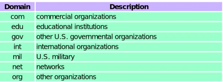
Figure 4.2 lists the normal classification of the seven generic domains.
Figure 4.2 The 3-character generic domains.
DNS folklore says that the 3-character generic domains are only for U.S. organizations, and the 2-character country domains for everyone else, but this is false. There are many non-U.S. organizations in the generic domains, and many U.S. organizations in the .us country domain. The only generic domains that are restricted to the United States are .gov and .mil.
Many countries form second-level domains beneath their 2-character country code similar to the generic domains:
.ac.uk, for example, is for academic institutions in the United Kingdom and .co.uk is for commercial organizations in the United Kingdom.
One important feature of the DNS that isn't shown in figures such as Figure 4.1 is the delegation of responsibility within the DNS. No single entity manages every label in the tree. Instead, one entity (the NIC) maintains a portion of the tree (the top-level domains) and delegates responsibility to others for specific zones.
A zone is a subtree of the DNS tree that is administered separately. A common zone is a second-level domain, fhr.de, for example. Many second-level domains then divide their zone into smaller zones. For example, a university might divide itself into zones based on departments, and a company might divide itself into zones based on branch offices or internal divisions.
If you are familiar with the Unix filesystem, notice that the division of the DNS tree into zones is similar to the division of a logical Unix filesystem into physical disk partitions. Just as we can't tell from Figure 4.1 where the zones of authority lie, we can't tell from a similar picture of a Unix filesystem which directories are on which disk partitions.
Once the authority for a zone is delegated, it is up to the person responsible for the zone to provide multiple name servers for that zone. Whenever a new system is installed in a zone, the DNS administrator for the zone allocates a name and an IP address for the new system and enters these into the name server's database. This is where the need for delegation becomes obvious. At a small university, for example, one person could do this each time a new system was added, but in a large university the responsibility would have to be delegated (probably by departments), since one person couldn't keep up with the work.
A name server is said to have authority for one zone or multiple zones. The person responsible for a zone must provide a primary name server for that zone and one or more secondary name servers.The primary and secondaries must be independent and redundant servers so that availability of name service for the zone isn't affected by a single point of failure.
The main difference between a primary and secondary is that the primary loads all the information for the zone from disk files, while the secondaries obtain all the information from the primary. When a secondary obtains the
information from its primary we call this a zone transfer.
When a new host is added to a zone, the administrator adds the appropriate information (name and IP address minimally) to a disk file on the system running the primary. The primary name server is then notified to reread its configuration files. The secondaries query the primary on a regular basis (normally every 3 hours) and if the primary
Domain Description
com commercial organizations edu educational institutions
gov other U.S. governmental organizations int international organizations
mil U.S. military net networks
org other organizations
contains newer data, the secondary obtains the new data using a zone transfer.
What does a name server do when it doesn't contain the information requested? It must contact another name server. (This is the distributed nature of the DNS.) Not every name server, however, knows how to contact every other name server. Instead every name server must know how to contact the root name servers. As of April 1993 there were eight root servers and all the primary servers must know the IP address of each root server. (These IP addresses are contained in the primary's configuration files. The primary servers must know the IP addresses of the root servers, not their DNS names.) The root servers then know the name and location (i.e., the IP address) of each authoritative name server for all the second-level domains. This implies an iterative process: the requesting name server must contact a root server. The root server tells the requesting server to contact another server, and so on.
We'll look into this procedure with some examples later in this chapter.
You can fetch the current list of root servers using anonymous FTP. Obtain the file netinfo/root-servers.txt from either ftp.rs.internic.net or nic.ddn.mil.
A fundamental property of the DNS is caching. That is, when a name server receives information about a mapping (say, the IP address of a hostname) it caches that information so that a later query for the same mapping can use the cached result and not result in additional queries to other servers.
4. TCP/IP Based Protocols
4.2. File Transfer Protocol
FTP is another commonly used application. It is the Internet standard for file transfer. We must be careful to differentiate between file transfer, which is what FTP provides, and file access, which is provided by applications such as NFS (Sun's Network File System). The file transfer provided by FTP copies a complete file from one system to another system. To use FTP we need an account to login to on the server, or we need to use it with a server that allows anonymous FTP.
Like Telnet, FTP was designed from the start to work between different hosts, running different operating systems, using different file structures, and perhaps different character sets. Telnet, however, achieved heterogeneity by forcing both ends to deal with a single standard: the NVT using 7-bit ASCII. FTP handles all the differences between different systems using a different approach. FTP supports a limited number of file types (ASCII, binary, etc.) and file structures (byte stream or record oriented).
RFC 959 is the official specification for FTP. This RFC contains a history of the evolution of file transfer over the years.
FTP differs from the other applications that we've described because it uses two TCP connections to transfer a file.
1.
The control connection is established in the normal client-server fashion. The server does a passive open on the well-known port for FTP (21) and waits for a client connection. The client does an active open to TCP port 21 to establish the control connection. The control connection stays up for the entire time that the client communicates with this server. This connection is used for commands from the client to the server and for the server's replies.The IP type-of-service for the control connection should be "minimize delay" since the commands are normally typed by a human user.
2.
A data connection is created each time a file is transferred between the client and server. (It is also created at other times, as we'll see later.)The IP type-of-service for the data connection should be "maximize throughput" since this connection is for file transfer.
Figure 4.3 shows the arrangement of the client and server and the two connections between them.
Figure 4.3 Processes involved in file transfer.
This figure shows that the interactive user normally doesn't deal with the commands and replies that are exchanged across the control connection. Those details are left to the two protocol interpreters. The box labeled "user interface"
presents whatever type of interface is desired to the interactive user (full-screen menu selection, line-at-a-time commands, etc.) and converts these into FTP commands that are sent across the control connection. Similarly the replies returned by the server across the control connection can be converted to any format to present to the interactive user.
This figure also shows that it is the two protocol interpreters that invoke the two data transfer functions, when necessary.
Data Representation
Numerous choices are provided in the FTP protocol specification to govern the way the file is transferred and stored. A choice must be made in each of four dimensions.
1.
File type.a.
ASCII file type.(Default) The text file is transferred across the data connection in NVT ASCII. This requires the sender to convert the local text file into NVT ASCII, and the receiver to convert NVT ASCII to the local text file type. The end of each line is transferred using the NVT ASCII representation of a carriage return, followed by a linefeed. This means the receiver must scan every byte, looking for the CR, LF pair.
b.
EBCDIC file type.An alternative way of transferring text files when both ends are EBCDIC systems.
c.
Image file type. (Also called binary.)The data is sent as a contiguous stream of bits. Normally used to transfer binary files.
d.
Local file type.A way of transferring binary files between hosts with different byte sizes. The number of bits per byte is specified by the sender. For systems using 8-bit bytes, a local file type with a byte size of 8 is
equivalent to the image file type.
2.
Format control. This choice is available only for ASCII and EBCDIC file types.a.
Nonprint.(Default) The file contains no vertical format information.
b.
Telnet format control.The file contains Telnet vertical format controls for a printer to interpret.
c.
Fortran carriage control.The first character of each line is the Fortran format control character.
3.
Structure.a.
File structure.(Default) The file is considered as a contiguous stream of bytes. There is no internal file structure.
b.
Record structure.This structure is only used with text files (ASCII or EBCDIC).
c.
Page structure.Each page is transmitted with a page number to let the receiver store the pages in a random order.
Provided by the TOPS-20 operating system. (The Host Requirements RFC recommends against implementing this structure.)
4.
Transmission mode. This specifies how the file is transferred across the data connection.a.
Stream mode.(Default) The file is transferred as a stream of bytes. For a file structure, the end-of-file is indicated by the sender closing the data connection. For a record structure, a special 2-byte sequence indicates the end-of-record and end-of-file.
b.
Block mode.The file is transferred as a series of blocks, each preceded by one or more header bytes.
c.
Compressed mode.A simple run-length encoding compresses consecutive appearances of the same byte. In a text file this would commonly compress strings of blanks, and in a binary file this would commonly compress strings of 0 bytes. (This is rarely used or supported. There are better ways to compress files for FTP.)
If we calculate the number of combinations of all these choices, there could be 72 different ways to transfer and store a file. Fortunately we can ignore many of the options, because they are either antiquated or not supported by most implementations.
Common Unix implementations of the FTP client and server restrict us to the following choices:
z Type: ASCII or image.
z Format control: nonprint only.
z Structure: file structure only
z Transmission mode: stream mode only.
This limits us to one of two modes: ASCII or image (binary).
This implementation meets the minimum requirements of the Host Requirements RFC. (This RFC also requires support for the record structure, but only if the operating system supports it, which Unix doesn't.)
Many non-Unix implementations provide FTP capabilities to handle their own file formats. The Host Requirements RFC states "The FTP protocol includes many features, some of which are not commonly implemented. However, for every feature in FTP, there exists at least one implementation."
Connection Management
There are three uses for the data connection.
1.
Sending a file from the client to the server.2.
Sending a file from the server to the client.3.
Sending a listing of files or directories from the server to the client.The FTP server sends file listings back across the data connection, rather than as multiline replies across the control connection. This avoids any line limits that restrict the size of a directory listing and makes it easier for the client to save the output of a directory listing into a file, instead of printing the listing to the terminal.
We've said that the control connection stays up for the duration of the client-server connection, but the data
connection can come and go, as required. How are the port numbers chosen for the data connection, and who does the active open and passive open?
First, we said earlier that the common transmission mode (under Unix the only transmission mode) is the stream mode, and that the end-of-file is denoted by closing the data connection. This implies that a brand new data connection is required for every file transfer or directory listing. The normal procedure is as follows:
1.
The creation of the data connection is under control of the client, because it's the client that issues the command that requires the data connection (get a file, put a file, or list a directory).2.
The client normally chooses an ephemeral port number on the client host for its end of the data connection.The client issues a passive open from this port.
3.
The client sends this port number to the server across the control connection using the PORT command.4.
The server receives the port number on the control connection, and issues an active open to that port on the client host. The server's end of the data connection always uses port 20.Figure 4.4 shows the state of the connection when the server issues the active open to the client's end of the data connection. The server's end point is at port 20.
Figure 4.4 FTP server doing active open of data connection.
The server always does the active open of the data connection. Normally the server also does the active close of the data connection, except when the client is sending a tile to the server in stream mode, which requires the client to close the connection (which gives the server the end-of-tile notification).
It is also possible for the client to not issue the PORT command, in which case the server issues the active open to the same port number being used by the client for its end of the control connection (5151 in this example). This is OK, since the server's port numbers for the two connections are different: one is 20 and the other is 21.
4. TCP/IP Based Protocols
4.3. Simple Mail Transfer Protocol
Electronic mail (e-mail) is undoubtedly one of the most popular applications. About one-half of all TCP connections are for the Simple Mail Transfer Protocol, SMTP. (On a byte count basis, FTP connections carry more data.) The average mail message contains around 1500 bytes of data, but some messages contain megabytes of data, because electronic mail is sometimes used to send files. Figure 4.5 shows an outline of e-mail exchange using TCP/IP.
Figure 4.5 Outline of Internet electronic mail.
Users deal with a user agent, of which there are a multitude to choose from. Popular user agents for Unix include MH, Berkeley Mail, Elm, and Mush.
The exchange of mail using TCP is performed by a message transfer agent (MTA). The most common MTA for Unix systems is Sendmail. Users normally don't deal with the MTA. It is the responsibility of the system administrator to set up the local MTA. Users often have a choice, however, for their user agent.
This chapter examines the exchange of electronic mail between the two MTAs using TCP. We do not look at the operation or design of user agents.
RFC 821 specifies the SMTP protocol. This is how two MTAs communicate with each other across a single TCP connection. RFC 822 specifies the format of the electronic mail message that is transmitted using RFC 821 between the two MTAs.
The communication between the two MTAs uses NVT ASCII. Commands are sent by the client to the server, and the server responds with numeric reply codes and optional human-readable strings. This is similar to what we saw with FTP.
There are a small number of commands that the client can send to the server: less than a dozen. (By comparison, FTP has more than 40 commands.) Rather than describing each one, we'll start with a simple example to show what happens when we send mail.
Simple Example
We'll send a simple one-line message and watch the SMTP connection. We invoke our user agent with the -v flag, which is passed to the mail transport agent (Sendmail in this case). This MTA displays what is sent and received across the SMTP connection when this flag is specified. Lines beginning with >>> are commands sent by the SMTP client, and lines beginning with a 3-digit reply code are from the SMTP server. Here is the interactive session:
sun % mail -v rstevens@noao.edu invoke our user agent To: rstevens@noao.edu this is output by user agent
Subject : testing we're then prompted for a subject
user agent adds one blank line between headers and body 1, 2, 3. this is what we type as the body of the message
. we type a period on a line by itself to say we're done
Sending letter ... rstevens@noao.edu... verbose output from user agent following is output by MTA (Sendmail) Connecting to mailhost via ether...
Trying 140.252.1.54... connected.
220 noao.edu Sendmail 4.1/SAG-Noao.G89 ready at Mon, 19 Jul 93 12:47:34 MST
Only five SMTP commands are used to send the mail: HELO, MAIL, RCPT, DATA, and QUIT.
We type mail to invoke our user agent. We're then prompted for a subject, and after typing that, we type the body of the message. Typing a period on a line by itself completes the message and the user agent passes the mail to the MTA for delivery.
The client does the active open to TCP port 25. When this returns, the client waits for a greeting message (reply code 220) from the server. This server's response must start with the fully qualified domain name of the server's host: noao.edu in this example. (Normally the text that follows the numeric reply code is optional. Here the domain name is required. The text beginning with Sendmail is optional.)
Next the client identifies itself with the HELO command. The argument must be the fully qualified domain name of the client host: sun.tuc.noao.edu.
The MAIL command identifies the originator of the message. The next command, RCPT, identifies the recipient.
More than one RCPT command can be issued if there are multiple recipients.
The contents of the mail message are sent by the client using the DATA command. The end of the message is specified by the client sending a line containing just a period. The final command, QUIT, terminates the mail exchange.
Figure 4.6 presents the mechanisms for the transmission of e-mail.
The amount of data we typed to our user agent was a one-line message ("1, 2, 3."), yet 393 bytes of data are sent in segment 12. The following 12 lines comprise the 393 bytes that are sent by the client:
Received: by sun.tuc.noao.edu. (4.1/SMI-4.1) id AA00502; Mon, 13 Sep 02 12:47:32 MST
Message-Id: <9307191947.AAO0502@sun.tuc.noao.edu.>
From: rstevens@sun.tuc.noao.edu (Richard Stevens) Date: Mon, 13 Sep 2002 12:47:31 -0700
Reply-To: rstevens@noao.edu X-Phone: +1 602 676 1676
X-Mailer: Mail User's Shell (7.2.5 10/14/92) To: rstevens@noao.edu
Subject: testing 1, 2, 3.
>>> HELO sun.tuc.noao.edu.
250 noao.edu Hello sun.tuc.noao.edu., pleased to meet you
>>> MAIL From: <rstevens@sun.tuc.noao.edu>
250 <rstevens@sun.tuc.noao.edu>... Sender ok
>>> RCPT To:<rstevens@noao.edu>
250 <rstevens@noao.edu>... Recipient ok
>>> DATA
354 Enter mail, end with "." on a line by itself
>>> .
250 Mail accepted
>>> QUIT
221 noao.edu delivering mail rstevens@noao.edu... Sent
sent. this is output by user agent
Figure 4.6 Model for SMTP use.
The first three lines, Received: and Message-Id:, are added by the MTA, and the next nine are generated by the user agent.