*kirsten.hacker@desy.de
OPTICAL REPLICA SYNTHESIZER TO BE RECOMMISSIONED WITH 270 nm SEED AT FLASH
Kirsten Hacker*, Robert Molo, Shaukat Khan, Technische Universitaet Dortmund, Germany Peter Salen, Peter Van der Meulen, Stockholm University, Sweden
Gergana Angelova Hamberg, Volker Ziemann, Uppsala University, Sweden Abstract
An Optical Replica Synthesizer (ORS) was commissioned at the Free Electron LASer in Hamburg, FLASH, in 2008 using an 800 nm seed. The experiment was affected by radiation from unwanted microbunches which were generated upstream of the experiment. Given new, 270 nm seeding infrastructure and the understanding that microbunches with separations smaller than 600 nm can effectively be smeared out in the dogleg of the machine, the experiment will be attempted again with this new wavelength. The new, 270 nm laser has been successfully overlapped with the electron beam in July 2012 and a measurement of the pulse energy which can be radiated in an optical replica will follow. The UV-TG- FROG diagnostic which will be used to measure the longitudinal profile of the optical replica has been delivered and is undergoing tests in a laser lab. Following these tests, it will be installed in the FLASH tunnel for the ORS experiments in 2013.
INTRODUCTION
Characterization of the relativistic and ultra-short electron bunches of a linac-based free electron laser (FEL) is important for machine operation. This need has triggered the development of several successful methods for measuring the longitudinal profile of the electron bunch, including the transverse deflecting cavity [1], electro-optical sampling [2], and single-shot THz spectrometer [3]. A different method for electron bunch characterization, called Optical Replica Synthesizer (ORS), was proposed in 2005 [4] and first attempted at the Free Electron LASer in Hamburg, FLASH, in 2008 [5].
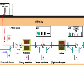
The ORS technique, depicted in Fig. 1, uses an external laser to produce seed pulses which interact with the electrons in an undulator, thereby modulating the energy of the electrons in a sinusoidal fashion. The energy modulation is transformed into a density modulation of the electrons in the following chicane. When the beam then traverses the undulator located downstream of this chicane, it radiates coherently and the emitted light pulse will have the same longitudinal profile as the electron beam; it is called the optical replica. The replica pulse and seed pulse are then extracted from the vacuum pipe by a mirror and directed onto an optical table where a polarizer can be used to separate the seed from the replica. This is facilitated by making the first planar undulator orthogonal ______________________________________________
Figure 1: ORS infrastructure. The beam energy is modulated by a laser pulse in the first undulator, bunched in the first chicane, and the optical replica is radiated in the second undulator with a polarization which is orthogonal to the seed laser pulse. The replica and the seed laser are then outcoupled in the second chicane and separated with a polarizer. The spectrum and spectral phase of the replica are measured with a FROG, thereby giving a measurement of the longitudinal profile of the electron beam.
to the second. The spectrum and spectral phase of the replica pulse can then be measured by a FROG (Frequency Resolved Optical Gating) device. This measurement directly gives the longitudinal profile of the electron bunch with a resolution that is ultimately limited by the slippage of the laser over the electron bunch as they co-propagate through a 5 period undulator with a period length of 20 cm. For our seed wavelength of 270 nm, this resolution limitation is around 5 fs, but practical considerations related to measuring extremely short laser pulses would likely limit the resolution of the measurement before the slippage plays a role.
The first attempt at demonstration of the ORS technique was conducted at FLASH in 2008 with an 800 nm seed [5] and for fully compressed bunches with several kA of peak current. It was affected by unwanted radiation from microbunches which were not generated through the interaction with the laser seed. This radiation produced a background to the optical replica signal and was not easy to filter out. These undesired microbunches have a broadband spectrum and are created/amplified by coherent synchrotron radiation in the upstream bunch
Proceedings of FEL2012, Nara, Japan TUPD14
Seeding and Seeded FELs
ISBN 978-3-95450-123-6 261 Copyrightc○2012bytherespectiveauthors
compressor chicanes. Measurements of how this microbunched beam structure evolves have been undertaken through single-shot THz spectrometers installed before and after the dogleg of FLASH (Fig. 2) [3]. They have shown that after the bunch travels through the dogleg of the machine, the broadband spectrum of the microbunches is truncated at shorter wavelengths. The mechanism is that the shorter wavelengths are smeared out transversely through a transverse-longitudinal coupling. The cut-off wavelength is determined by the beam size and R56 in the dogleg [6]. For a typical FLASH setup, this cut-off is around 600 nm and for an ORS to function, a seed wavelength of less than this value should be selected. We have selected 270 nm, the third-harmonic of radiation from a Titanium:sapphire laser, because it has been chosen for new seeding experiments starting this year [7].
Figure 2: FLASH machine layout. THz spectrometers are located before and after the dogleg, ORS is located at the beginning of the sFLASH section, and the transverse deflecting cavity is after the sFLASH section.
Direct-seeding infrastructure at FLASH was installed in 2010 under the project name sFLASH [9]. For sFLASH, an 800 nm laser is used to generate high harmonics in a gas jet. One of these harmonics is used to seed the electron bunch and make stronger, more longitudinally coherent FEL radiation than SASE can provide. In 2011, additional uses for this infrastructure, including ORS, electro-optical electron bunch form measurements, and Echo Enabled Harmonic Generation (EEHG), were proposed in [9]. The anticipated difficulties associated with parasitic operation of these experiments were explored in [10], simulations and tolerances for the EEHG experiment were described in [11], and the hardware and experimental setup for the EEHG experiment were detailed in [12]. For all of the schemes described in [10], a 270 nm beam must be injected into the electron beam line (Fig. 3). This infrastructure was built at the end of 2011 and has been commissioned in 2012 with longitudinal and transverse laser-electron overlap first attempted and achieved in July 2012.
sFLASH diagnostics, like YAG and OTR screens, spectrometers, streak camera, etc., have already been commissioned and are all ideally suited for use as ORS diagnostics. The transversely deflecting structure, LOLA, will be instrumental in diagnosing seed overlap and slice energy spread. It is the benchmark against which all ORS measurements can be compared having reached a resolution of 7 fs and 100 keV [1]. The primary component of the ORS experiment which has not been
commissioned is the FROG device. It is undergoing laboratory tests and it is anticipated that to measure the 1 kA beams which are typically present in FLASH today, further investment in evacuated-transport of the replica and a more sensitive FROG camera would be required.
Proof-of-principle measurements should, however, be possible in 2013 with higher, 3 kA peak currents.
SEED PROPERTIES
The sFLASH Ti:sapphire seed laser system produces 800 nm light with a pulse energy up to 30 mJ and a pulse length which can be adjusted between 30 fs and a picosecond. The laser and a pulse compressor are followed by a Galilean telescope on an optical table in a laser laboratory adjacent to the FLASH tunnel. After the telescope, the 16 mm (FWHM) diameter beam is periscoped down through a hole in the floor into a pit. The pit is connected to the accelerator tunnel by a 7 meter long tube. This is where the new, evacuated laser transport pipe starts with a 5 mm thick fused-silica window followed by 8 meters of evacuated pipe. The laser beam then enters the first of two 70x30x30 cm evacuated boxes installed in the accelerator tunnel. The evacuated boxes contain optical breadboards on which a frequency tripler, a polarization controller, and two motorized steering mirrors are mounted. Space for a Galilean telescope is available. Two more motorized steering mirrors are mounted on vacuum flanges on pipes following the boxes, the last of which reflects the laser beam onto the electron beam axis. A window directly after the last box marks the transition between the high vacuum (10-6 mbar) of the laser transport line and the ultra-high vacuum (10-9 mbar) of the accelerator. The 270 nm beam has a design pulse energy of 1-2 mJ for a pulse length of 170 fs (FWHM). More details on the setup can be found in [7-12].
UV-TG-FROG
A new FROG device has arrived from Swamp Optics and is undergoing tests in a laser lab. The FROG from the first ORS run at 800 nm could not measure UV pulses.
The new device is a Transient Grating (TG) type of FROG which overlaps 3 beams in a thin piece of glass [13]. Figure 4 shows the TG-FROG concept with transmissive optics. The custom design which was purchased utilizes the same principle as [13], but it is built with all-reflective optics, similar to [14].
In first tests with the device, a 70 fs (FWHM) long pulse with 70 μJ of pulse energy was measured with a filter in place which let only 30% of the UV light through, while blocking other wavelengths. The TG signal scales with the input pulse intensity cubed, so 140 fs pulses should require ~560 µJ and 35 fs pulses should require ~9 µJ. It is anticipated that, in its present configuration, the FROG can accurately measure down to 30-40 fs (FWHM) pulses and up to 200 fs long pulses, given enough single-shot pulse energy. The plan is to make it useful for measuring both the EEHG seeding experiment pulses [7] and the ORS pulses.
TUPD14 Proceedings of FEL2012, Nara, Japan
ISBN 978-3-95450-123-6 262
Copyrightc○2012bytherespectiveauthors
Seeding and Seeded FELs
Figure 4: UV-TG-FROG from www.swampoptics.com [13]. The same concept was used in the FROG purchased for ORS, but with reflective optics.
By replacing the 1 mm piece of glass with a thinner piece, one can enable the measurement of sub-30 fs pulses. Even few-cycle UV pulses as short as 4 fs have been measured with a similar method [15]. However, to measure such a short optical replica, the replica must be extracted from the electron beam line and measured before it is dispersed in a thick window or air. Presently, the 5 mm thick fused silica window through which the optical replica is coupled out of the electron beam line is followed by about one meter of air. If the ORS method is to be pushed towards its 5 fs limit, the window from the e- beam line would need to be replaced with a 1 mm thick crystalline quartz window which would serve as the boundary between the 10-9 mbar vacuum of the electron beamline and a 10-6 mbar vacuum chamber containing the FROG.
By reducing the thickness of the 1 mm glass, one would increase the input pulse energy requirements, but if the optical replicas do not have enough pulse energy, one can replace the existing camera with a more expensive, back- illuminated, cooled UV camera. This could gain a factor of 13-18 in terms of the quantum efficiency. Additional gains/losses in pulse energy requirements from filtration should also be expected.
ELECTRON BUNCH REQUIREMENTS
Through the optical synchronization system with longitudinal intra-bunch train feedback, 25 fs (rms) synchronization between seed and electron beam can be accessed for these experiments [16]. Due to the ~170 fs (FWHM) length of the seed pulses, the ORS experiment can only measure electron bunches which are much shorter than this and provided there is adequate overlap with the seed. Typical, present day SASE bunch lengths at FLASH are slightly shorter than this (50 - 100 fs (rms)) but there is a parallel research program in progress which aims at 10 fs (rms) bunches at FLASH [17].
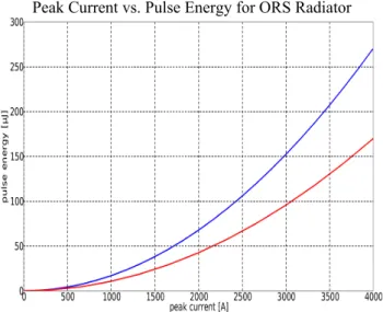
GENESIS [18] simulations of how much pulse energy can be expected of an optical replica for various electron bunch lengths and charges show that the 20 pC, 10 fs long bunches with 1 kA of peak current from [17] will only
radiate a couple of micro-Joules in an optical replica, while a possible SASE bunch with a 50 fs (rms) bunch length and 1 kA of peak current would radiate ~20 μJ. If the peak current is increased to 2 kA, it radiates ~40 μJ (Fig. 5). Higher peak currents are easily possible, but they they tend to produce beams with a larger emittance and energy spread.
Peak Current vs. Pulse Energy for ORS Radiator
Figure 5: Radiated pulse energy in an optical replica as a function of electron bunch peak current for a 50 fs (rms) bunch plotted in red and a 100 fs (rms) bunch shown in blue.
Since the electric field of the optical replica pulse is proportional to the current, the intensity goes with the square. Thus, a 50 fs (rms) electron bunch corresponds to an optical replica of about 80 fs (FWHM) for a Gaussian pulse form. The current FROG camera would require several times more pulse energy than would be radiated by a 1-2 kA bunch. Either more peak current or a more sensitive camera would enable the measurement of such bunches.
ADDITIONAL OPTION
Using the same 270 nm laser beam, the FROG may be used with an “electro-optical” technique to measure the same quantity as the ORS experiment [9]. The idea is that when the electron beam passes adjacent to an electro- optical medium, a laser beam will see the changes in the birefringence, transmittance or polarization of the medium. By measuring these changes with a FROG, one can measure the longitudinal profile of the electron bunch.
This technique is not typically attempted with a FROG as the diagnostic, because the pulse energy requirements are much higher than for a typical electro-optical experiment.
With up to a few milli-Joules of pulse energy, this is not something which is a problem for our setup. Operation in the UV also provides a venue for testing new electro- optical materials.
Proceedings of FEL2012, Nara, Japan TUPD14
Seeding and Seeded FELs
ISBN 978-3-95450-123-6 263 Copyrightc○2012bytherespectiveauthors
CONCLUSION
An Optical Replica Synthesizer (ORS) can be re- commissioned at FLASH in 2013 using a 270 nm seed.
The new experimental design seeks to avoid the problems with radiation from unwanted microbunches which drowned out the seeded optical replica signal for fully compressed electron bunches in the original, 800 nm version of this experiment conducted in 2008. To date, the 270 nm seed has been successfully overlapped with the electron beam and a measurement of the pulse energies which can be radiated in various optical replicas will follow. The UV-TG-FROG diagnostic which will be used to measure the longitudinal profile of the optical replica has been delivered and is undergoing tests in a laser lab setting. Following these tests, it will be installed in the FLASH tunnel for the EEHG seeding and ORS experiments planned for 2013. Significant enhancements to the FROG setup would be required for it to measure typical SASE bunches at FLASH, but it will be possible to use it in the present configuration on a proof-of- principle basis to measure bunches with higher peak currents. The research is conducted to determine the viability of an upgrade targeted at measuring 10 fs (rms), 20 pC bunches.
ACKNOWLEDGEMENTS
This work was supported by DESY, BMBF 05K10PE1, and grant 621-2009-2926 of the Swedish research council.
REFERENCES
[1] C. Behrens, et al., Constraints on photon pulse duration from longitudinal electron beam diagnostics at a soft x-ray free-electron laser, Phys. Rev. ST Accel. Beams 15, 030707 (2012).
[2] B. Steffen, Electro-optic methods for longitudinal bunch diagnostics at FLASH, Univ. Hamburg DESY- THESIS-2007-020.
[3] S. Wesch et al., A multi-channel THz and infrared spectrometer for femtosecond electron bunch diagnostics by single-shot spectroscopy of coherent radiation, Nucl. Inst. and Methods A 665 (2011) 40.
[4] E. Saldin, et al., A simple method for the determination of the structure of ultrashort relativistic electron bunches, Nucl. Inst. and Methods A 539 (2005) 499.
[5] P. Salen, et al., Results from the optical replica synthesizer experiment at FLASH, FEL 2009, Liverpool, England (THOB02).
[6] E.A. Schneidmiller and M.V. Yurkov, Phys. Rev. ST Accel. Beams 13, 11070 (2010).
[7] K. Hacker, et al., Progress towards HGHG and EEHG seeding at FLASH, this conference.
[8] C. Lechner, et al., sFLASH: direct seeding at 38.1 nm, this conference.
[9] K. Hacker, et al., New uses for the ORS section at FLASH, TESLA-FEL-NOTES-2011-03.
[10] K. Hacker, Requirements for parasitic operation of the ORS section, TESLA-FEL-NOTES-2011-04.
[11] K. Hacker, et al., Tolerances for echo-seeding in the FLASH ORS section, TESLA-FEL-NOTES-2011- 05.
[12] K. Hacker, et al., Progress towards echo-seeding in the FLASH ORS section, TESLA-FEL-NOTES- 2011-06.
[13] D. Lee, et al., Experimentally simple, extremely broadband transient-grating frequency-resolved- optical gating arrangement, Optics Express 15 (2007) 766.
[14] T. Nagy, et al., Single-shot TG FROG for the characterization of ultrashort DUV pulses, Optics Express 17 (2009) 8144.
[15] U. Graf, et al., Intense few-cycle light pulses in the deep ultraviolet, Optics Express 16 (2008) 1856.
[16] W. Koprek, et al., Optical synchronization system at FLASH, Proc. of FEL’10 (Malmoe).
[17] J. Roensch-Schulenburg, et al., Generation of ultra- short electron bunches at FLASH, this conference, THPD33.
[18] S. Reiche, GENESIS 1.3: a fully 3D time-dependent FEL simulation code, Nucl. Instr. and Meth. A 429 (1999).
TUPD14 Proceedings of FEL2012, Nara, Japan
ISBN 978-3-95450-123-6 264
Copyrightc○2012bytherespectiveauthors
Seeding and Seeded FELs