Integrating Software Process Models and Design Rationales’
Barbara Dellen*, Kirstin Kohler+, Frank Maurer* 2
*SFB 501, UniversiW Kaiserslautern, P.O. Box 3049, D-67653 Kaiserslautern, Germany email: { delleqmaurer} @informatik.uni-kl.de
‘Hewlett-Packard GmbH, D-7 1034 BBblingen, Germany
Abstract
In this paper we describe an approach which allows us to acquire, represent and managejne-grained causal depen- dencies between products. These dependencies are basi- cally derived automatically from a software process model. By representing causal dependencies and their rationales, the traceability of software development pro- cesses is improved. Our dependency-based system is able to support users in reacting on changes. Thereby, the costs of software development can be reduced. Based on the the- oretical work, the CoMo-Kit System was implemented consisting of a modeling component and a process engine.
The use of the system is illustrated in the last section.
1 Introduction
Long-term goal of our work is to improve software engineering processes. The techniques described below increase the traceability of the processes within software development. This is necessary in order to better under- stand, coordinate, change, and verify them.
Nowadays, the development of complex software sys- tems is carried out by large teams of domain experts, sys- tem analysts, software designers, and programmers. The size of the teams leads to a high coordination, develop- ment, and maintenance effort which is a main cause of
increasing software costs.
Another reason for high maintenance costs lies in the nature of software projects: they are time consuming and are characterized by requirements which are often changed during the project lifetime. A purposeful reaction to changing requirements, which is reliant on the trace- ability of the development processes, can drastically reduce software costs.
The size of the development teams and the long project periods lead to three requirements on SE Tools:
* The spatial and temporal distribution of working pro- cesses requires that the tool documents decisions in a way that other or later users can understand them.
l The tool should be an ,,intelligent memory“ of its users and manage the basis every single decision was taken on.
l After changes, the tool should automatically notify the affected users.
During development processes, the people involved make a huge number of decisions which are based on former decisions and which may influence future deci- sions. To make the resulting decision processes planable, understandable, and controllable, several techniques were developed. Two techniques and their problems have been the starting point of the work presented here:
l Software process modeling [8, 29, 121 deals with explicit representation of development processes (espe- cially of the information flow). An explicit representa- tion helps to understand, to plan, to control, to analyze and to trace the workflow in software development projects. Software process models are typically coarse- grained. They do not contain e.g. an activity which defines one requirement [ 17,20, 181. Therefore, they are too coarse-grained to automatically derive causal depen- dencies between one requirement and parts of the sys- tem design and the source code. However, the acquisition and representation of these fine-granular dependencies is necessary to trace the effects of a requirement which is changed.
* The term ,,Design Rationale“ [l, 15, 301 subsumes approaches which deal with the acquisition and the management of fine-grained (design) decisions and their dependencies. One problem of published approaches is that justifications must be entered interactively by the
1, This work was sponsored in part by the Deutsche Forschunggemeinschaj? as part of the special research activity Sonderforschungsbereich 501 ,,Development of large systems with generic methods”.
2. In alphabetical order.
users. This causes them an additional effort in doing his model. Furthermore, traceability of the daily work and reduces the acceptability of design ratio- cess is improved so that is it possible to
nale systems. to changes.
Goal. In this paper methods and techniques are described coarse which automatically extract causal dependencies between
design decisions from development task decompositions and from the information flow of fine-grained software pro- cess models.
In software and knowledge engineering domains, deci- sions are taken by different persons. Coordinating their work includes notifying every member of the development team about decisions or decision changes within the project.
To reach this goal, we developed methods and techniques which automatically inform team members about changes.
Therefore, our system extracts causal dependencies (design rationales) between decisions from development task decompositions and from the information flow of fine- grained software process models. Unfortunately, in practical situations it is not possible to guarantee that a fine-grained process model contains all the necessary and no unneces- sary dependencies. So, our system also allows the interac- tive manipulation of the automatically derived design rationales.
$
,,coarse-grained”
P
process models 2
2
:~
Jine-grained”
process models 0.
z design
rationales fine
Figure 1: Software Process Models & Design
To model software processes, we extended conventional Knowledge Engineering approaches [2, 4, 91. To handle dependencies efficiently, we use Reason Maintenance Sys- tems.
In the next section we define basic notions of the lan- guage which is used in CoMo-Kit to model processes. Sec- tion 3 describes causal dependencies which can be automatically extracted from process models. section 5 deals with dependencies which cannot be automatically derived. To enact process models we developed a workflow engine which manages causal dependencies based on AI techniques. The functionality of this workflow engine is sketched in section 6. An example which illustrates the functionality of our system is given in section 7. In section 8 related work is discussed. The last section summarizes this paper and gives an overview on future work.
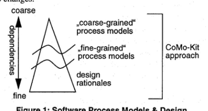
Our system integrates process modeling and design rationale approaches. The connection between these approaches is clarified in Figure 1. Published (,,coarse- grained“) process models [ 17,20, 181 describe development processes on a very high level of abstraction. Therefore, only a small number of causal dependencies can be derived from them automatically (Typically at the level: where the requirements specification influences the design and the design influences the implementation). If these models are refined, as proposed here, many more causal dependencies can be automutically extracted. The effort of building these fine-grained process models is additionally justified, pro- ceeding on the basis that the models are stored in a library (or ,,Experience Factory“ [(Victor R. Basili and Gianluigi Caldiera and H. Dieter Rombach: Experience Factory.
Encyclopedia of Software Engineering, Vol. 1, pages 469- 476, John J. Marciniak (Editor), John Wiley & Sons,
1994)]) and will be reused.
2 Process Modeling in CoMo-Kit
Within the CoMo-Kit project of the University of Kaiser- slautern techniques, methods, and systems are developed which support planning and enacting complex distributed cooperative design processes [22, 231. One focus of atten- tion are techniques to acquire causal dependencies between design decisions and to help users react to changes.
The techniques developed currently are used in two application domains: Urban Land-Use Planing [24] and Software Engineering.
To model cooperative design processes, our approach uses four basic notions: Tasks, Methods, Products (Con- cepts) and Agents. In the following, these terms are defined as far as is necessary to understand this paper.
Design rationale approaches represent fine-grained causal dependencies which are acquired from the user dur- ing project enactment. These dependencies are not automat- ically derived by the systems.
The integration of these approaches, as proposed in our CoMo-Kit project, leads to synergy effects. The work load of users is reduced because an essential part of the causal dependencies is automatically derived from the process
Tasks. A task describes a goal to be reached while enact- ing a process. Every task is related to a set of input and out- put parameters’. When tasks are enacted, decisions are made which result in assignments of values to the output parameters. Our approach assumes that there is a causal dependency between the inputs and the outputs of a task.
We work on the principle that during model construction only inputs are associated to a task which are relevant and
1. Parameters are also called ,,variables“.
development pro- react purposefully
necessary for reaching the goal (Inadequacies of this assumption and their solutions are discussed in section 5).
Products (Concepts}. To model products which are cre- ated in the course of process enactment (e.g. a requirement document), an object-centered approach is used. As usual, we distinguish between classes and instances. Classes define a set of slots to structure the product. Every slot is associated with its type and cardinality. Types may be other product classes or basic types (e.g. SYMBOL, STRING, REAL, . ..). Product classes are used to type parameters in information-flow graphs. During process enactment we rep- resent product instances as values which are assigned to variables. The type of a variable is specified by a product class. Products can be modeled on a fine-grained level. For example, individual requirements can be described as one product and the requirements document as another. The lat- ter one would consist of several of the former.
Methods. To solve a task, a method is applied. For every task, there may exist a set of alternative methods. Methods are carried out by agents (see below).
We distinguish between atomic and complex (or com- posed) methods. Atomic methods assign values to parame- ters. Complex methods are described by an information flow graph. An information flow graph consists of nodes which define parameters and (sub)tasks and of links which relate parameters to tasks. The direction of the link deter- mines if the parameter is the input or the output of the task.
Every parameter is associated with a product type: During process enactment, the parameters, represented as variables, may store instances of this product type. Subtasks can be further decomposed by complex methods. Along this line, the decomposition of the overall task (e.g. ,,develop Soft- ware“) can be seen as an AND-OR-Tree where tasks are AND-Nodes and methods are OR-Nodes. The appropriate method of solving a task is selected during process enact- ment.
Agents. Tasks are handled by agents. For every task, the process model defines the agents which may work on it. We distinguish two kinds of agents: Humans and computers.
For computers, methods are described in an operational lan- guage (Smalltalk-80).
The defined framework allows the construction of mod- els of arbitrary software engineering processes (for example the Waterfall Model or the IEEE Standard 1074- 1991 pro- cess model). The question which remains is how causal dependencies can be automatically extracted from these models.
3 Managing Causal Dependencies during Process Enactment
During design of a process model methods are related to tasks and the information flow between the tasks is specified [22]. Our system deduces dependencies automatically from these structures. These dependencies serve as a basis for reacting on changes during process enactment. Therefore, the postulated dependencies have to be made explicit and managed with a suited mechanism [lo] [23].
In the first subsection we clarify important terms. In sec- tion 4.1 and section 4.2, the two types of causal dependen- cies which are automatically derived from a process model are described.
The dependencies are formulated as logical implications.
The formalization allows to store the required process infor- mation within an ,,intelligent memory“ and to automate the notification of users after changes. Another advantage is that the semantic of the dependencies is made explicit. The decision finding process itself is not formalized. What we do, is the formalization of the dependencies resulting from the decision.
4 Decision, Rejection of a Decision and Rationale
We understand by rationales arguments pro and con a decision or fact. The rationales we deduce from the process model can be formulated as logical implications.
A decision is the resolution to apply a method to reach a goal. By choosing a complex method, the agent determines how to proceed. It decides for example to make an object- oriented design. The decision for an atomic method means the instantiation of a product class. For example, the deci- sion for an atomic method generates a test case for a pro- gram. The decision as to which of the alternative methods of a task is applied, depends on the context of process enact- ment.
To reach a decision is the task of the agent, but the sys- tern can give decision support by making available valid input data and current rationales pro or con the different alternatives to him. Based on this information he takes a decision for one alternative. The process of coming to a decision itself is not automated, only the resulting decision is stored and handled by the system. The system further- more able to tie rationales pro or con the alternatives in the dependency managing mechanism.
To allow the formulation of rationales pro or con a deci- sion on a technical base, we formalize the terms in form of logical predicates. Predicates can be valid (true) or invalid (false).
A decision for a method mi is expressed by a predicate decision(mJ. It stays valid as long as the associated method is the actual solution. The rejection of a method mi is described by a predicate rejected-decision(mJ. The validity of the predicate means that the decision can not be part of the current solution. Therefore, method mi is no alternative in the present state of the development. The relation between the two predicates is shown in Equation .
rejected-decision(mi) * 7decision(mi)
The validity of the predicate rejected-decision(mJ implies the invalidity of the decision for method mi (predi- cate decision(mi)). Equation is not an equivalence relation:
Suppose, the decision for mi is retracted for some reason.
The responsible agent decides to proceed with another method, say m,. If the reason to retract the decision for mi becomes invalid, the agent could resort to alternative mp By returning to the old method, the effort spent in working on method m, was useless. Returning to the old method can be very expensive. An equivalence relation would just lead to such a behavior, because the invalidity of the predicate rejected-decision(mi) would automatically validate the deci- sion for l?li.
This can be demonstrated by an example. An enterprise usually gets hardware for its products from an external sup- plier. The supplier is currently having difficulties with deliv- ery. Therefore the enterprise contracts another supplier.
Even if afterwards the first supplier were able to deliver the hardware, the enterprise wouldn‘t retract its current deci- sion. The costs and the expenditure would be too high.
In summary, the introduction of the two predicates deci- sion and rejected-decision allows us to determine, if a method contributes to the actual project plan, to handle con- ditions for the validity/invalidity of a decision or the rejec- tion of a decision, and to state rationales pro or con the validity of tasks and products.
Putting it altogether, we define the following semantic for the validity of a decision: A decision is valid if all sup- porting arguments are valid, and no argument for the rejec- tion is valid.
The following subsections deal with the question what kind of rationales can be extracted from the process model and how they are represented.
4.1 Dependencies within the Information Flow During the enactment of tasks, information is used and produced. The process model specifies which information is used/produced and states the type of the information. Figure 2 shows the information flow for a task T. I, 0, and 02 are formal parameters (variables) of products. They define the type of a product and give a name to a product instance within the process model. T consumes a product, referenced by variable I. It produces products named 01 and 02.
Causal dependencies, which are described in the following, can be derived from these relations.
.Task T
0 Task
@ Information (Producttype) __) Direction of the information flow
Figure 2: Information flow of a task T Producing Information
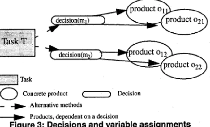
Products are created by applying atomic methods. Prod- ucts are values which are bound to variables. During pro- cess enactment the result of applying an atomic method is associated with the corresponding decision. Figure 3 shows this relation. Methods ml and m2 represent different solu- tions for task T. Solving T by applying method ml binds the values oll and 021 to the variables OZ and 02. Another assignment of the variables, namely o12 and 022 results from the decision for m2. We can say that the rationale for a vari- able assignment (for example oll and 02Z) is the validity of the corresponding decision. By retracting the decision, the resulting assignments also become invalid.
0
Concrete product () Decision _ + Alternative methods__) Products, dependent on a decision
Figure 3: Decisions and variable assignments The described dependencies can be formulated as logical implications. Formally, the assignment of a variable is expressed by the predicate assignment(V=value). The fol- lowing formula states, that by applying mj the output vari- ables 01 to 0, are bound with values OZj to Ovj
decision(mj) =+ assignment(Ol=olj) A
assignment(0~=02j) A . ..A assignment(O,=O,j) (Eq 1) If the decision mj looses its validity, the assignments become invalid, too. The rationale for an concrete assign- ment is the validity of its associated decision.
Using Information
Decisions are made within the context of the actual input information of a task. Usually the input information has
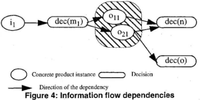
been produced by solving another task within the develop- ment process. The direction of the information flow is spec- ified in the process model. Further decisions are taken based on the actual input. As described in the previous section, (parts of) products can be removed from the repository by retracting the corresponding decision. By applying another method other assignments become valid and the present information changes. If a decision bases on the old informa- tion, it has to be retracted, too, because its foundation is lost. Figure 4 illustrates this. Based on the valid input il the
0
Concrete product instance (-3 Decision __) Direction of the dependencyFigure 4: Information flow dependencies
decision for method ml has been reached. By applying ml the products oll and 021 have been created which had been the foundation for the decisions decision(n) and decision(o) respectively. When retracting the decision that justifies the validity of i, the decision for ml looses its rationale. As a result, the decisions for II and o become invalid, too. This behavior can spread through a chain of decisions with (partly) global effects on the development process.
To handle these effects, we deduce from the process model the described dependencies, formalized in Equation 3. The variables ZI to In refer to the context, in which deci- sion mk has been taken. The predicates assignment(Zl=ilk) to assignment(Z,=i,k) stand for the k-th assignment of the variables Z1 to In with values ilk to j&
7assignment(li=i,k) v . . . v ,assignment(l,=i& *
rejected-decision(mk) (Eq 2)
If one of the input values ilk to j,& becomes invalid, mk will be rejected. Because of the dependency of Equation 1 (section 4), the predicate decision(mk) becomes invalid, too.
The resulting formulas connect products and decisions.
By the explicit representation of the described dependen- cies, changes within the process enactment can be traced.
4.2 Dependencies between a Task & its Subtasks
Complex methods decompose tasks in a set of subtasks.
If an agent decides to apply a complex method the set of (sub)tasks related to the method becomes part of the actual project plan and has to be solved.
The validity of the subtasks depends on the decision for the corresponding complex method. If the decision for the
method is rejected, the rationale for the validity of the resulting subtasks is no longer given. The subtasks have to become invalid. Decisions, which have been taken within the subtasks, must be rejected too.
Formally, mi represents a complex method, which divides a task in subtasks Tl to TV We define a predicate validSubTask(Tj) as follows. The predicate is valid, if the corresponding task Tj is part of the actual project plan and invalid otherwise.
decision(p) +
validSubtask( T,) A validSubtask( T2) A . . A
validSubtask( TV) Fq 3)
The validity of the subtasks TI to TV depends on the validity of the decision for mi.
We do not deduce rationales for the rejection of a deci- sion of a complex method from the process model. This fact can be described by the following formula.
false 3 rejected-decision(m$ Fq 4)
Equation 4 is necessary as an anchor for adaptations described in the next section.
5 Adaptation of Causal Dependencies during Process Enactment
All dependencies described in the previous sections are generated automatically based on a process model. In our applications we recognized that process models contain not all necessary or some unnecessary dependencies. This defi- ciency of the models can have different underlying reasons:
Models represent generic structures that do not fit the actual project down to the last detail. Some models lack dependencies, we call them incomplete models. Some models describe unnecessary dependencies, they are named overloaded models.
In many situations during the enactment of the project, further steps depend on results (e.g. products) of the pre- vious steps. For example during the design of a particular component, the designer considers a given requirements from the requirement document, but all requirements to consider were unknown when the process model was cre- ated, The problem is, that these dependencies between particular requirements and a component become evident only during the enactment of the process and can never be extracted from a model. We call this phenomenon situa- tion dependent decisions.
To handle the described deficiency, the system allows agents to manipulate the existing dependencies dynamically during the process enactment. This adaptation refers only to the dependencies given by the flow of information (cf. Sec- tion 4.1). The adjustments deal with justifications of design decisions, i.e. with arguments for or against the selection of a particular method.
For adaptation purposes, we distinguish two cases:
l Incomplete models and situation dependent decisions demand an extension of existing dependencies by addi- tional justifications.
l In overloaded models it is necessary to remove justifica- tions, that were automatically derived from the process model. Removing unnecessary justifications restrict the change propagation to those subparts of the process, that are affected by a change.
l In the following sections, we describe the dynamic adap- tation of dependencies during the process enactment. Sec- tion 5.1 deals with the extension of existing justifications.
We explain the forms of justification we distinguish and our method of expressing these justifications. The removal of existing justifications is illustrated in Section 5.2.
5.1 Extending Existing Dependencies by Addi- tional Justifications
The Representation of Additional Justifications We distinguish two forms of additional justifications:
l Arguments to support the selection of a particular method, and
l arguments to deny the selection of a particular method.
If we speak about justifications in a general sense, we refer to both forms of justifications. To accentuate the dif- ference between the two cases, we call them arguments for the validity of a decision and arguments for the rejection of a decision.
Our system offers several means of describing additional justifications:
l Justifications by previous decisions,
l justifications by existing products, and
l informal textual justifications.
The following account explains these possibilities in more detail. On connection with this, we attempt to clarify the benefit of different representation forms.
Justification by previous decisions: An actual decision could be influenced by decisions reached in previous steps.
For example; an Agent chooses the method ,,functional design“ because the decision for a ,,functional analysis“ of the software development process was reached in an earlier step. In this case, the decision ,,functional analysis“ is a jus- tification for the decision ,,functional design“.
Justification by existing products: An actual decision could be influenced by a product that was produced as a result of a former task in the process. For example the rea- son why a developer decides for a the method ,,object-ori- ented design“ within the task ,,develop system architecture“
was the nonfunctional requirement ,,implementation in Smalltalk‘. This requirement is a part of the requirement document, that was created as an artifact of the Software
Development Process in the task ,,define requirements“. The decision for the method ,,object-oriented design“ is justified by the product ,,implementation in Smalltalk“
Both decisions and products are handled by our system.
The user can reference them as part of his new justification.
References to those elements are the basis for supporting change propagation.
If the ,,implementation in Smalltalk“ was changed in the example above, our systems could propagate this to the decision ,,object-oriented design“.
Informal textual justification: The user may add a text to justify his decision. This practice is useful for those justifi- cations, which cannot be referenced by an existing product or previous decision. This kind of justification provides a simple opportunity to save information for further process- ing steps. The text is associated with the corresponding decision. It is obvious that a textual justification cannot sup- port an automatic change propagation. But it is a useful way of preserving the users deliberations. The information could be helpful, if for example a designer tries to understand a former design during rework.
The following subsections describe how adding of justi- fications affects the causal dependencies. By adding justifi- cations the formulas described in Section 3 are extended.
We concentrate on justifications by previous decisions and existing products. These justifications are the more impor- tant ones in supporting change propagation.
Clearly, the user is not confronted with the logical for- mulas, rather he manipulates the dependencies through a graphical user interface (cf. Section 7).
Justifying the Validity of Decisions
Justifications by previous decisions: A new decision decision(m,,,) is taken on the basis of one or more recent decisions decision(m,ldI) . . decision(m,ldM). The decision decision(m,ew) must become invalid, if at least one of the decisions decision(m,ldI) . . decision(m,tdM) loses its valid- ity. To give a formal description of this dependency, we expand Equation 2 with the disjunction of the negated pred- icates decision(m,tdI) . . decision(m,ldM).
The additional justifications change the condition for the rejection as demonstrated in the following formula (Italic characters in following equations signal the additional justi- fications):
7assignment(li=ilk) v . . . v 7assignment(l,=i,k) v 7decision(mOldt) v . . . v 7decision(m,ldM)
3 rejected-decision(m,,,) (Eq 5)
Justijications by existing products: A new decision decision(m,,,) is made on the basis of one or more existing products assignment(X1=xoldl) . . . assignment(X,=x,l&, e.g.: a decision is justified by a particular requirement in the requirement document. The decision has to become invalid if at least one of the products assignment(X1=xoldl) . . .
assignment(X,=x,ldM) loses its validity. To give a formal description of this dependency, we expand Equation 2 with the disjunction of the negated predicates assign- ment(x]=x&fl) ,,. assignment(&=x&&.
The additional justifications change the condition for the rejection as demonstrated in the following formula:
7assignment(li=ilk) v . . . v 7assignment(l,=i,k) v 7assignment(Xl=x0,J v . . . v 7assignment(XM=x0,&
+ rejected-decision(m,,) (Eq 6)
Justifying the Rejection of Decisions
Justifications by previous decisions: A new decision
design document influences the implementation. However if one special design decision in the design changes, it is not necessary to reject the whole implementation seeing as most components are not affected by this design decision.
For this reason the user can select the (parts of) products, which do not influence a decision and those dependencies are removed. As a result, a change to this product will not be propagated to the decision.
We achieve the adaptation of the logical description by removing the related predicate (assignment(I,=i,&) of the product, that does not influence the decision. This causes the following change in Equation 2:
decision(m,,,) is rejected on the basis of one or more recent decisions decision(m,ldl) . . decision(m,ldM). The decision decision(,,,) has to become invalid, if at least one of the decisions decision(m,ldl) . . decision(m,ldM) becomes valid.
To give a formal description of this dependency, we expand Equation 2 with the disjunction of the predicates deci- sion(m&]) . . decision(m&&
The additional justifications change the condition for the rejection as demonstrated in the following formula:
7assignment(li=iljJ v . . . v 7assignment(l,.l=i,.lk) *
rejected-decision(m,,,) 6% 9)
All adaptations in Section 4 can be applied to the same decision. They do not exclude each other.
Up to now, we have described the logical foundation of our work. The next section gives an overview of our work- flow management server which handles all dependencies described above.
-7assignment(li=ilk) v . . . v 7assignment(l,=i,k) v
6 Workflow management with Co&lo-Kit
decision(m,,& v v decision(mO,dm)
=+ rejected-decision(m,,,) Fq 7)
Justifications by existing products: A new decision decision(m,,,) is made on the basis of one or more existing products a.@nment(XI=x,ldl) . . . assignment(x,+&M) (for example: the decision is justified by a particular requirement in the requirement document). The decision has to become invalid if at least one of the products assign- ment(xl=x,ldl) . . . aSsignment(&=XO[&,~ becomes valid. To give a formal description of this dependency, we expand Equation 2 with the disjunction of the predicates assign- ment(xl=x&l) . . . assignment(X,=x,ldM).
The additional justifications change the condition for the reject as demonstrated in the following formula:
In addition to tools for developing process models, CoMo-Kit contains a workflow management system, the CoMo-Kit Scheduler. The Scheduler operationalizes the process models and allows to enact planning and design processes interactively [lo] [23]. The workflow server is responsible for
l managing all causal dependencies described in this paper,
l storing all information produced during process enact- ment,
l managing the actual state of the design process,
* supporting the retraction of decisions, and
l discovering and solving inconsistencies in the problem solving process.
-7assignment(li=ilk) v . . . v 7assignment(l,=i,k) v assignment(Xl=xOld,) v . . . v assignment(XM=x,,dM)
+ rejected-decision(m,,,) (Eq 8)
5.2 Deleting Justifications
The general planning and design model REDUX [25] is the basis for the implementation of the CoMo-Kit Scheduler and can be seen as a specifically structured TMS. REDUX supports task decomposition and dependency-directed backtracking. Our Scheduler extends this functionality by managing information flow dependencies.
Justifications of design decisions, which are automati- cally derived from the model, describe dependencies con- tained in the information flow. If some of those dependencies are irrelevant for a particular decision in the current project, it is necessary to delete them. As a result of this adaptation our system operates only on significant justi- fications.
This is essential to restrict the change propagation to those parts of the process that are affected by a change. An example illustrates this: In the process model the entire
In the development of large software systems a huge set of tasks and decisions must be managed and coordinated.
These are related to each other by complex information flows. It is imperative that the huge resulting set of depen- dencies has to be handled efficiently. A closer look shows that changing one decision only influences a small set of formulas. Accordingly, only a small number of formulas change their logical state. This feature of the domain is the basis for improving the efficiency of our dependency man- agement.
To handle all logical implications, we use a Truth Main- tenance System (JTMS [l 11) known from Artificial Intelli- gence. The underlying idea of an TMS is to record in which formulas a predicate is used. When a predicate changes its logical state, the formulae which are influenced can effi- ciently update their states. So, after a change not every for- mula has to be accessed, but only those which may be influenced by the change.
7 Example
The following example illustrates our approach. Figure 6 displays a small part of a software process model, modeled using our CoMo-Kit system. It shows the decomposition of tasks by methods.
Figure 5: Task decomposition
Rectangles represent tasks and rectangles with rounded corners depict methods. To reduce the complexity of the example, we normally define only one method for every task. For example, the method standard was defined for the task SojIware Development and decomposes it in three sub- tasks (Characterize Problems, Define Requirements and Design).
In the first step of process enactment, the Scheduler derives the following implication with Equation 3 based on the process model. It establishes the causal dependency between the overall task and its subtasks:
decision(sfancfard) 3
validSubtask( Charaderise Problems) A validSubtask(Define Requirements) A
validSubtask(Design) (Eq 10)
If, in further enactment of the process, the method Requirements is selected to solve task Define Requirements, then a second implication is generated:
decision(Requirements) 3
validSubtask(Requirements for User Interface) A validSubtask( Requirements for Algorithms) A
validSubtask(Requirements for Data Manage4 (Eq 11) Predicate decision(Requirements) is valid after the impli- cation was generated. If it becomes invalid, the state of all subtasks switches also to ,,invalid“. Then the Scheduler notifies the users working on these subtasks that the work on the tasks can currently be suspended or stopped.
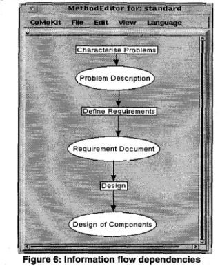
In addition to the dependencies derived from task decompositions, the Scheduler handles information flow dependencies. In figure 1, the information flow of the
Figure 6: Information flow dependencies
method standard is shown. Again, rectangles depict tasks whereas ellipses are parameters.
One can see that, for example, task Define Requirements needs a document of type Problem Description as input and produces an output of type Requirements Document. Then this document is used by task Design. To reduce the com- plexity of the example no finer-grained dependencies between product parts are defined. However, the Scheduler automatically derives dependencies between product parts, too.
Based on Equations , 1 and 2 the Scheduler generates the following implications while enacting task Define Require- ments:
,assignment(PD=can problem description>) +.
rejected-decision(Atomic:Define Requirements) (Eq 12) rejected-decision(Atomic: Define Requirements) j
7decision(Atomic: Define Requirements) 03 13) decision(Atomic: Define Requirements) *
assignment(RD=ean requirements document>) (Eq 14) If, during further process enactment, the assignment of parameter PD with the instance <a problem description> of class <product description> becomes invalid, the method Atomic:Dejine Requirements is rejected and therefore the decision decision{Atomic: Define Requirements) becomes invalid. As a result, the assignment of variable RD with the requirements document <a requirements document>
becomes invalid too. Because of other information flow
dependencies, which are not given here, the Scheduler prop- agates these changes further with the result that many deci- sions and product instances may become invalid.
One can see that causal dependencies derivable from the process model support traceability only to a certain degree.
In the example it may be desirable to trace design decisions back to single requirements. For example, during the design process the user has decided that the system architecture should consist of 3 components. Using techniques described in section 5 developers are able to justify the design of com- ponents by concrete requirements.
8 Related work
Several approaches exist which support the modeling and the enactment of software engineering processes. Two of them, Marvel [16] and GRAPPLE [14], integrate AI techniques similar to our CoMo-Kit approach.
Marvel follows a rule-based approach to express assumptions for the enactment of process steps. The approach supports forward-chaining of rules as well as backward reasoning. The latter tests which actions must be undertaken to fulfill the precondition of the current action.
Marvel does not support justifications for choosing a method nor is it possible to express causal dependencies between products and decisions.
GRAPPLE is based on an explicit model of planning.
Using an operator-based language supports the representa- tion of preconditions of actions. GRAPPLE plans in a goal- oriented manner. It contains a plan recognition component which interprets user actions and integrates them into the actual plan. In GRAPPLE it is assumed that, for planning and plan recognition process, knowledge is needed which is not included in operator definitions. This knowledge is given as a set of assumptions and handled by a RMS. Con- trary to our approach, this knowledge is mainly used to con- strain the set of applicable operators. Causal Dependencies between products are not explicitly represented in GRAP- PLE.
The language MVP-L [5] developed by the group under Prof. Rombach at the University of Kaiserslautern supports the modeling and enactment of software processes. The MVP-System does not handle causal dependencies and therefore change propagation is not supported. Currently, we integrate CoMo-Kit with the MVP approach [31].
[6,30] give an extended overview on systems which explicitly manage rationales for decisions in design pro- cesses. Many of these approaches use argumentation-based notations to represent justifications.
The best known notation is IBIS (Issue Based Informa- tion System)[28]. Its elements and their extensions are the basis for most of the other systems.
Although there are similarities in the representation for- malism, CoMo-Kit can be distinguished from argumenta- tion-based systems. gIBIS[7] and QOC (Questions Options Criteria)[21] describe techniques which are used to repre- sent the argumentation space and show arguments, con- flicts, and possible solutions explicitly (representing deliberations). Their main focus is the development of argu- mentation structures. In contrast, CoMo-Kit stores justifica- tions and dependencies to propagate effects of changes in software development processes. Therefore, representing justifications in CoMo-Kit not only clarifies possible deci- sions for the user but also enables a computer-supported reaction to new versions of products.
In CoMo-Kit, justifications are directly related to prod- ucts of the development process by associating appropriate assignments. This is useful because often decisions are made based on properties of products. A comparable con- nection between justifications and products can be found in REMAP [27] and DIG (Design Information Gathering Sys- tem) [13]. Both systems manage justifications to support software maintenance. REMAP and DIG force their users to enter all dependencies manually. On the contrary, the CoMo-Kit Scheduler automatically generates an essential part of all justifications based on the information flow.
Users only have to adapt them to their current needs. The adaptation is supported by a graphical interface which allows the easy manipulation of the extracted structures. So, CoMo-Kit relieves the users from entering justifications to a degree which surpasses other systems.
To manage justifications, CoMo-Kit uses REDUX struc- tures [25]. REDUX manages dependencies between a task and its subtasks. Additionally, CoMo-Kit extracts causal dependencies from the information flow.
9 Summary and future work
This paper describes the integration of design rationale approaches and software process models. Our workflow management server, the CoMo-Kit Scheduler, manages dependencies which are derived automatically from fme- grained process models as well as manually entered justifi- cations in a single representation. We extended conventional Knowledge Engineering techniques to model software pro- cesses. The lack of the standard Knowledge Engineering approaches is that the process model has to be completed before the process enactment starts. Causal dependencies are managed by a Truth Maintenance System (TMS) famil- iar from Artificial Intelligence, which is able to handle the huge number of logical implications generated by our sys- tem efficiently. The propagation algorithm of the TMS allows to update the logical value of formulas efficiently after product or project changes. On the basis of dependen-
ties, the CoMo-Kit Scheduler is able to find out which deci- sions, tasks, and products are tackled by a change and thus can notify the appropriate users. The team members have access to rationales for decisions and can react appropriate.
The given support results in an improved coordination abil- ity and therefore supports the management of large software development projects.
For many design decisions some sort of fuzzy reasoning (e.g., strong, medium, and weak true along with strong, medium, and weak false) seem to be more suitable to describe how a decision is reached. Our system only man- ages ,,hard“ facts and not the fuzzy evaluation process.
Our system is implemented in Visualworks for Small- talk-80 and the object-oriented database ,,GemStone“.
10 References
[II PI
AAAI ‘92 Workshop on Design Rationale Capture and Use, July 151992, San Jose, CA.
J. Angele, D. Fensel, D. Landes, S. Neubert, R. Studer:
Model-based and Incremental Knowledge Engineering: The MIKE Approach. In Knowledge Oriented Software Design, J.
Cuena, ed. IFIP Transactions A-27, Elsevier, Amsterdam, 1993,139-168.
[31 Victor R. Basili and Gianluigi Caldiera and H. Dieter Rom- bath: Experience Factory. Encyclopedia of Software Engi- neering, Vol. 1, pages 469-476, John J. Marciniak (Editor), John Wiley & Sons, 1994
[41 PI
[61
[71
PI
[91
J. Breuker, W. van de Velde (eds.): CommonKADS Library for Expertise Modelling, 10s Press, 1994.
A. Brockers, C. M. Lott, H. D. Rombach, and M. Verlage.
MVP-L language report version 2. Technical Report 265/95, Department of Computer Science, University of Kaiserslau- tern, 67653 Kaiserslautem, Germany, 1995.
S. Buckingham Shum and N. Hammond. Argumentation- based design rationale: what use at what cost? Int. J. Human- Computer Studies, 40:603-652, 1994.
Conklin, J., Begeman. gIBIS: A Tool for Exploratory policy Discussion, In Proceedings of CSCW ‘88 and ACM Transac- tions on Ofice Information Systems, October, 1988.
B. Curtis, M. I. Kellner, and J. Over, Process modeling. Com- munications of the ACM, 35(9):75-90, September 1992.
R. de Hoog, W. Menezes, C. Toussaint, B. J. Wielinga, R. M.
Taylor, C. Bright, W. van de Velde: The CommonKADS model set, ESPRIT Project P 5248 KADS-II/Ml/DM..lb/
UvA/O18/5.0, University of Amsterdam, Lloyd’s Register, Touche Ross & Free University of Brussels.
[lo] B. Dellen, F. Maurer, J. Paulokat: Verwaltung von Abh&n- gigkeiten in kooperativen, wissensbasierten Arbeitsablaufen.
In Proceedings of the 3. deutschen Expertensystemtagung, pages 72-89, 1995
[l l] Doyle, J.: A Truth Maintenance System, Artificial Intelli- gence, 12:231-272, 1979.
[12] P. H. Feiler and W. S. Humphrey. Software process develop- ment and enact ent: Concepts and definitions. In Proceed- ings of the 2n P International Conference on the Software Process, pages 28-40. IEEE Computer Society Press, Febru- ary 1993.
[13] M. Hamada, H. Adachi, Recording Software Design Pro- cesses for Maintaining the Software, Proc. 17th International Computer Software & Applications Conference, COMP- SAC-93, IEEE Computer Society, 1993.
[ 141 Karen Erikson Huff: Plan-Based Intelligent Assistance: An Approach to Support the Development Process. PhD thesis, University of Massachusetts, September 1989
[15] A. Jarczyk, P. Loffler and F. Shipman, Design Rationale for Software Engineering: A Survey. In V. Milutinovic et al., edi- tor, Proceedings of the 2jth Internationale Conference on System Science, Los Alamitos, Ca, USA, Jan. 1992
[ 161 G.E. Kaiser P.H. Feiler, S.S. Popovich: Intelligent Assistance for Software Development and Maintenance, IEEE Software, May 1988.
[ 171 Marc I. Kellner, Peter H. Feiler, Anthony Finkelstein, Takuya Katayama, Leon J. Osterweil, Maria H. Penedo, H. Dieter Rombach. Software Process Modeling Example Problem.
IEEE CSP, October 1990.
[18] Marc I. Kellner, H. Dieter Rombach. Session Summary:
Comparisons of Software Process Descriptions. IEEE Press, October 1990.
[ 191 J. Lonchamp. A structured conceptual and terminological framewo$ for software process engineering. In Proceedings of the 2n International Conference on the Software Process, pages 41-53. IEEE Computer Society Press, February 1993.
[20] M. Lubars, Representing design dependencies in an issue- based style, IEEE Software, July 1991.
[21] A. Mac-Lean et al.: Questions, Options and Criteria; Ele- ments of Design Space Analysis. Human-Computer Interac- tion, 6: 201-250, 1991.
[22] Maurer, F.: Hypermedia-Based Knowledge Engineering for Distributed Knowledge-Based Systems (in german), Disser- tation Universitat Kaiserslautem, 1993, such: DISK1 48, infix-Verlag, ISBN 3-929037-48-3.
[23] Maurer, F., Paulokat, J.: Operationalizing Conceptual Models Based on a Model of Dependencies, in: A. Cohn (Ed.): ECAI 94. 1 lth European Conference on Artificial Intelligence, 1994, John Wiley & Sons, Ltd.
[24] Maurer, F., Pews, G.: Ein Knowledge-Engineering-Ansatz fur kooperatives Design am Beispiel der Bebauungsplanung, Themenheft Knowledge Engineering, KI l/95, interdata Ver- lag, 1995.
[25] Petrie, Ch.: Planning and Replanning with Reason Mainte- nance, Dissertation, University of Texas, Austin, 1991.
[26] C. Petrie and M. Cutkosky. Design space navigation as a col- laborative aid, in J. Gero and F. Sundweeks, editor, Artificial Intelligence in Design ‘94, Kluwer Academic Publishers, 1994
[27] B. Ramesh and V. Dhar: Representing and Maintaining Pro- cess Knowledge for Large-Scale Systems Development, IEEE Expert, ~01.9, no.2, April 1994.
[28] H. Rittel: Second generation design methods (1972).
Reprinted in N. Cross, editor, Developments in Design Meth- odology, pages:317-327,1984
[29] H. D. Rombach and M. Verlage. Directions in software pro- cess research. In M. V. Zelkowitz, editor, Advances in Com- puters, vol. 41. Academic Press, Boston, MA, 1995.
[30] Special Issue on Design Rationale, Human-Computer Inter- action, 6: 197-419, 1991.
[31] M. Verlage, B. Dellen, F. Maurer, J. Munch: A Synthesis of Process Support Approaches, ICSE-96.