CERN-LHCC-2015-020/LHCC-G-166 25/09/2015
ATLAS
Phase-II Upgrade S coping D ocument
September, 2015
ATLAS
Phase-II Upgrade
Scoping Document
Revision: 1.0
Reference: CERN-LHCC-2015-020 LHCC-G-166
Created: March 1, 2015 Last modified: September 25, 2015 Prepared by: The
ATLAS
CollaborationContents
I Preface 1
II Overview of the ATLAS Phase-II upgrade program 3
II.1 Roadmap to High Luminosity LHC . . . . 5
II.2 Performance and Physics objectives and comparative studies . . . . . 6
II.3 Reference and alternative scoping scenarios . . . . 7
II.3.1 Trigger and Data Acquisition . . . 8
II.3.2 Inner Tracker . . . 8
II.3.3 Calorimeters . . . 10
II.3.4 Muon spectrometer . . . 11
II.3.4.1 Barrel detectors . . . 11
II.3.4.2 End-cap chambers . . . 13
III Trigger and Data Acquisition System 14 III.1 Introduction . . . . 15
III.2 Level-0 Triggers . . . . 17
III.2.1 Level-0 Muon Triggers . . . 17
III.2.2 Level-0 calorimeter Triggers . . . 19
III.3 Level-1 Triggers . . . . 20
III.3.1 L1Track . . . 20
III.3.2 L1Global . . . 21
III.4 Central Trigger Processors . . . . 23
III.5 Data Acquisition and Data-flow . . . . 23
III.5.1 Detector Readout . . . 23
III.5.2 Data-flow . . . 24
III.6 Event Filter . . . . 25
III.6.1 FTK++ . . . 25
III.7 Trigger Menus . . . . 26
III.8 Areas where R&D is needed . . . . 28
III.9 Prototyping and R & D plans . . . . 30
III.10 Cost Estimate . . . . 30
III.11 Cost risk analysis . . . . 31
III.12 Summary Schedule . . . . 33
IV Inner Tracker 34
IV.1 Introduction . . . . 35
IV.1.1 Design, layout and differences with the existing tracker . . . 35
IV.2 Detector layout scenarios and rapidity coverage . . . . 37
IV.2.1 Reference scenario layout . . . 37
IV.2.2 Middle scenario layout . . . 38
IV.2.3 Low scenario layout . . . 39
IV.3 The Pixel detector . . . . 41
IV.3.1 Pixel modules . . . 42
IV.3.2 Sensors . . . 43
IV.3.3 Pixel front-endASIC . . . 45
IV.3.4 Output Data Transmission . . . 46
IV.3.5 Mechanics and Services . . . 46
IV.4 The Strip detector . . . . 47
IV.4.1 Strip Sensors . . . 49
IV.4.2 Modules and ReadoutASICs . . . 50
IV.5 Common ITk Items . . . . 50
IV.5.1 Readout . . . 50
IV.5.2 Powering scheme . . . 52
IV.6 Ongoing R&D activities . . . . 52
IV.7 R&D plans and time-line . . . . 53
IV.8 Cost estimates . . . . 55
IV.8.1 Cost of Forward Pixels . . . 55
IV.8.2 Pixel Staves and Discs . . . 55
IV.8.3 Strip Staves and Petals . . . 57
IV.8.4 Support Mechanics . . . 57
IV.9 Cost Risks . . . . 58
IV.9.1 Pixels . . . 58
IV.9.2 Strips . . . 58
IV.9.3 Common Items . . . 58
IV.10 Schedule Summary . . . . 59
V Calorimeters 62 V.1 Overview of the Calorimeter upgrades . . . . 63
V.2 LAr Calorimeter Read-out Electronics . . . . 64
V.2.1 Incompatibility of the Current Readout Electronics withHL-LHCDesign Requirements64 V.2.2 Readout Architecture Studies and R&D forHL-LHC . . . 64
V.2.3 Low Voltage Powering Systems . . . 70
V.2.4 R&D Timeline and Technology Selection . . . 71
V.2.5 Cost Estimates . . . 71
V.2.5.1 Cost Drivers and Cost Risk Analysis . . . 72
V.2.6 Schedule and Milestone Summary . . . 73
V.3 Tile Calorimeter Electronics . . . . 73
V.3.1 Electronics Overview andHL-LHCChallenges . . . 74
V.3.2 Electronics for HL-LHC . . . 75
V.3.3 R&D for Phase-II Upgrades . . . 78
V.3.4 Strategy for Selecting FinalFEB,HVOptions . . . 80
V.3.5 Cost Estimates, Cost Drivers and Risks . . . 81
V.3.6 Summary Schedule and Milestones . . . 82
V.4 Forward Calorimetry . . . . 83
V.4.1 Performance of the LAr FCal at HL-LHC luminosities . . . 83
V.4.2 The high-granularity sFCal . . . 84
V.4.3 The MiniFCal . . . 86
V.4.3.1 TheLAr MiniFCaloption . . . 87
V.4.3.2 The warmMiniFCaloption . . . 87
V.4.4 Timeline and Decision Path . . . 89
V.4.5 Cost Estimates . . . 89
V.4.5.1 Cost Drivers and Cost Risk Analysis . . . 90
V.4.6 Schedule and Milestone Summary . . . 91
V.5 High Granuarity Timing Detector (HGTD) . . . . 91
V.5.1 HGTDin the gap between theLArbarrel and end-cap cryostats . . . 92
V.5.2 Detector technologies under investigation . . . 93
V.5.3 Time-line . . . 95
V.5.4 Cost Estimates . . . 95
V.5.4.1 Cost Drivers and Cost Risk Analysis . . . 95
V.5.5 Schedule and Milestones Summary . . . 96
VI Muon Spectrometer 97 VI.1 Introduction . . . . 98
VI.2 Upgrade of the MDT read-out electronics . . . . 101
VI.2.1 Reference scenario . . . 101
VI.2.2 Reduced scenarios . . . 102
VI.2.3 R&D activities and plans . . . 102
VI.3 Upgrade of the muon trigger electronics . . . . 102
VI.3.1 Upgrade of the muon barrel RPC trigger electronics . . . 102
VI.3.2 Upgrade of the muon end-cap TGC trigger electronics . . . 104
VI.3.3 R&D activities and plans . . . 104
VI.4 Upgrade of the RPC and MDT Chambers in the Barrel . . . . 104
VI.4.1 Reference scenario . . . 104
VI.4.2 Reduced scenarios . . . 108
VI.4.3 R&D activities and plans . . . 108
VI.5 Upgrade of the TGC chambers in the inner ring of the Big Wheel . . . . 108
VI.5.1 Reference scenario . . . 108
VI.5.2 Reduced scenarios . . . 109
VI.5.3 R&D activities and plans . . . 109
VI.6 Integration of MDT chambers in the trigger system . . . . 109
VI.6.1 Reference scenario . . . 109
VI.6.2 Reduced scenarios . . . 111
VI.6.3 R&D activities and plans . . . 111
VI.7 Muon tagger for high η . . . . 111
VI.7.1 Reference scenario . . . 111
VI.7.2 Reduced scenarios . . . 112
VI.7.3 R&D activities and plans . . . 112
VI.8 Replacement of power supplies . . . . 112
VI.9 Costs . . . . 114
VI.9.1 Cost drivers and risk analysis . . . 114
VI.10 Schedule and milestones . . . . 114
VII Forward Detectors 116 VII.1 Introduction . . . . 117
VII.2 AFP . . . . 117
VII.3 ZDC . . . . 118
VII.4 LUCID . . . . 119
VII.5 Summary . . . . 122
VIII Infrastructure and Installation 123 VIII.1 Introduction . . . . 124
VIII.2 Safety and Radio-protection . . . . 125
VIII.2.1 Radiation simulations . . . 125
VIII.2.2 Radiation protection requirements . . . 129
VIII.2.3 Radiation protection equipment . . . 130
VIII.3 Layout and configurations . . . . 130
VIII.4 Installation schedule . . . . 131
VIII.4.1 Schedule assumptions . . . 132
VIII.4.2 Overall sequence of the installation process . . . 133
VIII.4.3 Schedule details . . . 136
VIII.5 Beam-pipe . . . . 136
VIII.6 Installation common tools . . . . 137
VIII.6.1 ITkmechanical installation . . . 137
VIII.6.2 Cryostat opening and closing . . . 138
VIII.6.3 Movement and installation of Barrel Muon chambers . . . 138
VIII.7 Point-1 Infrastructures . . . . 139
VIII.7.1 Upgrade of electrical network . . . 139
VIII.7.2 Upgrade of rack cooling . . . 139
VIII.7.3 Cabling . . . 140
VIII.7.4 Cooling and ventilation . . . 140
VIII.7.5 Network and software . . . 141
VIII.7.6 DCS . . . 141
VIII.8 Assembly buildings and storage space . . . . 141
VIII.8.1 Assembly and integration . . . 141
VIII.8.2 Workshop . . . 142
VIII.8.3 Storage . . . 142
VIII.9 Cost Estimates . . . . 142
IX Summary of Cost and Schedule 144 IX.1 CORE Project Costs for each Scenario . . . . 145
IX.2 Required Manpower . . . . 146
IX.3 Schedule and Milestones . . . . 148
IX.4 Required Funding Profile . . . . 148
X Project Management Plan 151 X.1 Project Organisation . . . . 152
X.2 Project Phases . . . . 153
X.3 Review Strategy . . . . 154
X.3.1 Internal Reviews . . . 154
X.3.2 Review Office Reviews . . . 155
X.3.3 Strategic Upgrade Reviews . . . 155
X.3.4 IDR Process . . . 155
XI Performance and Physics 157 XI.1 Introduction . . . . 158
XI.2 Physics object performance . . . . 158
XI.2.1 Trigger . . . 159
XI.2.2 Tracking performance . . . 159
XI.2.3 Primary vertex finding . . . 166
XI.2.4 Electron performance . . . 168
XI.2.5 Photon reconstruction . . . 169
XI.2.6 Muon reconstruction and identification . . . 173
XI.2.7 Jet reconstruction and pile-up rejection . . . 174
XI.2.7.1 Jet energy scale . . . 174
XI.2.7.2 Pile-up jet rejection . . . 175
XI.2.7.3 Pile-up jet simulation . . . 175
XI.2.7.4 Performance gains from the high-granularitysFCal . . . 177
XI.2.7.5 Performance gains from the high granularity timing detector . . . 179
XI.2.8 Missing transverse energy . . . 181
XI.2.9 Flavour tagging . . . 181
XI.2.10 Tau performance . . . 184
XI.3 Physics Potential and Selected Analyses . . . . 186
XI.3.1 Inclusive Higgs boson production withH→ZZ(∗)→µ+µ−µ+µ− . . . 187
XI.3.2 Studies of the VBFH→ZZ(∗)→`+`−`+`−process . . . 188
XI.3.3 Studies of the VBFH→WW(∗)→`ν`νprocess . . . 192
XI.3.4 Studies ofW±W±boson scattering in the final state with two same charge leptons and two jets . . . 195
XI.3.5 Search for charginos and neutralinos in final states with one lepton and two b-jets . 198 XI.3.6 Search for resonant pair production of Higgs bosons in the fourb-jet final state . . 200
XII Summary and Conclusions 204 XII.1 Summary of Scoping Scenarios . . . . 205
XII.1.1 Reference Detector . . . 205
XII.1.2 Components of Scoping Scenarios . . . 206
XII.2 Impact on Physics Object Performance . . . . 207
XII.2.1 ITk Impacts . . . 207
XII.2.2 TDAQ Impacts . . . 208
XII.2.3 LAr Impacts . . . 209
XII.2.4 Muon Impacts . . . 209
XII.2.5 Impacts of Large-ηOpportunities . . . 209
XII.3 Summary of Physics Studies . . . . 210
XII.4 Conclusions . . . . 211
Glossary 222
References 223
Chapter I
Preface
The High Luminosity upgrade of theLarge Hadron Collider (LHC)(HL-LHC) is currently expected to begin operations in the second half of 2026, with a nominal levelled instantaneous luminosity of L ' 5×1034cm−2s−1 corresponding to an average, µ, of roughly 140 inelastic pp collisions each beam-crossing, and delivering an integrated luminosity of around 250 fb −1 per year of operation.
The
ATLAS
collaboration described their initial plan and goals for the corresponding Phase-II up- grade of the detector, intended to take full advantage of this accelerator upgrade, in the Letter of Intent [1] in 2012. Since that time, the accelerator team has announced the goal of achieving an ul- timate luminosity ofL '7.5×1034cm−2s−1corresponding an averageµ=200inelastic ppcollisions per beam-crossing. This programme aims to provide a total integrated luminosity of 3000 fb−1 by 2035. TheATLAS
collaboration has been refining and improving their Phase-II upgrade plans since the LoI document was submitted, incorporating lessons learnt from the initial Run 1 operation of the LHC, from further evolution of the initial design, and from the results of a task force which evaluated specific options to extend the pseudo-rapidity coverage of the inner tracking detector, and related detectors such as the muon system.TheLHC Experiment Committee (LHCC), theUpgrade Cost Group (UCG), and CERN manage- ment have agreed on a detailed plan for the review and approval of the
ATLAS
andCMS
Phase-II upgrade projects. This plan has been described in an LHC Research Review Board (LHC-RRB) document, which is now being finalised [2]. The present document, referred to as the Scoping Documentin this process, is intended to address a broad range of questions relevant to the initial stage of formal approval for theATLAS
Phase-II upgrade project. Three different upgrade configu- rations have been defined, corresponding to three costing scenarios, with total CORE costs of about 200 MCHF, 235 MCHF, and 275 MCHF respectively. These three scenarios are described in detail in the present document, including the relevant R&D and prototyping results. The current estimates of approximate total CORE project costs, manpower, schedule and the corresponding funding profile, in sufficient detail to allow a meaningful review, are also included. Finally, a list of the Technical Design Reports (TDRs)for each of the proposed Phase-II upgrades, and an overall plan with mile- stones and schedules for producing them, are presented. The corresponding plan and schedule for the remaining R&D and prototyping required to define final designs and provide cost and schedule estimates for theTDRs, are summarised.The different scenarios have been designed to provide information on performance versus cost for the major cost drivers of the Phase-II upgrade, including the large inner tracker, which com- prises roughly 50% of the total upgrade cost, as well as the trigger and data-acquisition system, the calorimeter systems, and the muon spectrometer. For each scoping scenario, detailed studies have been performed to estimate the expected performance for physics objects such as tracks, primary vertices, electrons, photons, muons, jets, heavy-flavour jets, and missing transverse energy. The performance is estimated for the highest instantaneous luminosity expected from theHL-LHC, with µ=200. In some cases, the performance is explored at reduced values of instantaneous luminosity corresponding toµ=140(the nominalHL-LHCluminosity). In addition, the performance of the data- acquisition and triggering systems, and their impact on the triggering capability of
ATLAS
, have been parameterised in the form of a simplified trigger menu for each scenario. These results are then used to extract the expected physics performance of the Phase-II upgrade for a selected set of benchmark physics processes, covering Electroweak and Higgs boson physics, as well as searches for Supersymmetry and more exotic manifestations of new physics processes. The contributions of individual components of the upgrades can be disentangled to give an approximate estimate of the impact of the scoping scenarios on the performance and physics metrics. The final evaluations of the different scenarios, based on these performance and physics studies, are summarised in ChapterXII.Chapter II
Overview of the ATLAS Phase-II
upgrade program
This document describes the strategy of the
ATLAS
collaboration for its Phase-II upgrade. It provides a supplement and an update to the original Letter of Intent (LoI) [1] dating from 2012.In particular, it provides a detailed presentation of the scope and performance of the detector and trigger system upgrade for each of the three scoping scenarios defined by the
ATLAS
collaboration to correspond to the three cost targets defined by the CERN management at theLHC-RRBmeeting of April 2015 [2].The
ATLAS
LoIdocument addressed the Phase-II upgrade for the accelerator scenario in which the peak levelled luminosity was taken to beL ' 5×1034cm−2s−1, corresponding toµ'140, where µ is the the average number of collisions per crossing. Since that time, the HL-LHC project has introduced an ultimate levelled luminosity scenario with L ' 7.5×1034cm−2s−1, corresponding to µ'200. This scenario explores the technical limits of theLHCcapabilities, andATLAS
has carried out a number of simulation studies with µ' 200 to ensure that the Phase-II detector upgrade is capable of taking full advantage of the ultimate luminosity.These studies, extending techniques developed for the 2012 Run 1 data withµ'25, lead to a more complete understanding of the challenges of operation atµ' 200, particularly in the area of mitigation of pile-up effects from these additional events. In addition, a Task Force was established by the
ATLAS
collaboration in early 2014 to evaluate possible extensions to theLoIdetector design for Phase-II, with a particular emphasis on the regions with|η|> 2.5. The pile-up values in the range of µ' 140−200, and the greater understanding of the role of the forward region of the detector in the Phase-II physics program, have motivated a set of additions to the originalLoIdetector pre- sented in 2012. This has led to the definition of the Reference scenario detector layout, optimised for luminosities up to the ultimate luminosity configuration (µ'200). At the present time, this is the de- tector configuration which is intended to maximise the physics performance and discovery potential of the experiment during theHL-LHCperiod. It corresponds approximately to the 275 MCHF costing guideline [2]. The two alternative scenarios, with an approximate cost of 235 MCHF and 200 MCHF, are referred to hereafter as the Middle and Low scenarios, respectively.The three scoping scenarios include different configurations for the upgrade of each major sys- tem in the
ATLAS
detector. They focus in particular on theInner Tracker(ITk) and on theTrigger and Data Acquisition (TDAQ)systems, as these are the most expensive components of the Phase-II upgrade. The impact on performance of the three costing scenarios is assessed in this document.This in turn allows an evaluation of the physics program that could be possible in each scenario.
The changes in scope for the Middle and Low scenarios have their largest impact on the triggering and reconstruction of leptons, jets, b-jets and missing transverse momentum at the higherµvalues.
Both triggering and reconstruction are essential to acquire the statistics needed to address critical measurements in the electroweak sector, as well as to extend the searches for new particles and new phenomena beyond the Standard Model. The impact on the physics potential is assessed using detailed studies of the expected detector performance for different physics objects, which are then parametrised to provide simple “smeared truth” simulations of the complete physics analyses with all backgrounds and signals included. This approach was developed for the ECFA 2013 [3] and 2014 [4] workshops, and is further extended here to evaluate the representative measurements and searches described in SectionII.2and, in more detail, in ChapterXI.
The preparation of theTDRsfor the
ATLAS
upgrade projects will take place in the period from now until the end of 2017. ChapterXdescribes the organisation and schedule for the activity in this period, system by system. The activity will include extensive and detailed simulations, and additional iterations and refinements of the designs presented in this document. At that time, a broader range of performance studies, and physics analyses for benchmark processes, will be carried out. In the context of the Scoping Document, the studies have focused on a smaller set of physics processes, which take advantage of the full integrated luminosity possible with the HL-LHCprogramme. Fur-thermore, the selection of analyses presented, which is summarised in Table1, is tailored to explore many of the issues that are most relevant for the proposed scoping scenarios.
Chapter XIIprovides the overall summary of the document by integrating together the perfor- mance and physics results of ChapterXIwith the detailed descriptions of the upgrades in Chapters III –VIII. This leads finally to the conclusion of the scoping exercise, where the performance and physics advantages of the Reference scenario, and the performance and physics disadvantages of the Low scenario, both relative to the Middle scenario, are briefly summarised.
II.1 Roadmap to High Luminosity LHC
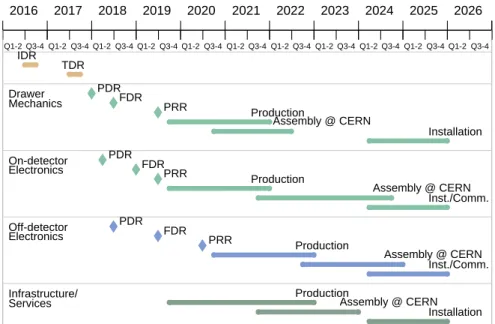
The schedule for the upgrades to the LHC accelerator complex, leading to theHL-LHC, is shown in Fig.1[5]. This schedule has been recently updated according to the CERNMedium Term Plan (MTP) for the period 2016-2020, which was presented at the last CERN Council session [6] in June 2015. The complete accelerator and detector upgrades are expected to be progressively installed during the next two major shutdowns of the accelerator complex, defined as LS2 (currently scheduled to take place in 2019-2020 and to last for 24 months) and LS3 (currently scheduled to take place in 2024-2026 and to last for 30 months).
Figure 1.High Luminosity LHC plan beyond 2015, updated according to the CERNMTPfor 2016-2020 (from Ref. [5])
At the beginning of the operation of theHL-LHCin the second half of 2026, it is expected that the
ATLAS
experiment will have acquired a data sample corresponding to an integrated luminosity of ap- proximately 300 fb−1. The target integrated luminosity for theHL-LHCprogram, during an operating period of roughly 10 years (with a nominal rhythm of 3 years of operation and 1 year of shutdown, or roughly 8 years of accelerator operation) is intended to provide ten times more integrated luminosity, or 3000 fb−1. In order to achieve this extraordinary goal, an ultimate performance of the accelera- tor complex, based on achieving an instantaneous levelled luminosity ofL ' 7.5×1034cm−2s−1and delivering more than 300 fb−1per year, is required.This scenario, which implies extended periods of operation, and therefore full performance and physics capability, at µ'200, has been considered as the design goal for the Phase-II
ATLAS
upgrade. Most of the performance and physics results in this document are therefore evaluated at µ'200, although some studies have been performed at the lower values ofµ'140(correspondingtoL ' 5×1034cm−2s−1) and atµ'80 (the maximum pile-up conditions expected at the end of the Run 3 period before HL-LHC operation begins). Many of the features present in the Reference design scenario are essential to achieve the required trigger and reconstruction performance when operating in the highest pile-up configurations (µ' 140−200). The goal of optimal performance at µ'200is especially challenging given the strong dependence of critical elements of the programme on efficiently triggering and reconstructing physics processes that involve the production of the W andZbosons, and especially Higgs bosons in a wide range of decay modes.
II.2 Performance and Physics objectives and comparative studies
The physics programme of the LHCluminosity upgrade is presented and discussed in detail in the Phase-II Upgrade LoI[1] and in the two reports submitted to the European Committee for Future Acceleartors (ECFA)[3,4]. In this document, the trigger and offline reconstruction performance of electrons and photons, muons, jets, b-jets and EmissT have been studied extensively in each of the scoping scenarios. The results of those studies are reported in SectionXI.2.
In addition, several physics processes have been analysed to evaluate the impact of the different upgrade scenarios proposed. The physics analyses focus primarily on precision measurements for the 125 GeV Higgs boson, on vector-boson scattering, and on searches for signatures of new physics. A few selected analyses, shown in Table1, are presented in detail in SectionXI.3to draw attention to specific components of the
ATLAS
upgrade programme, and to the benefits that those upgrades provide in terms of improved performance for the relevant physics objects.Table 1. Overview of the physics analyses described in this document, and of the associatedATLASsub- systems whose upgrades may impact the physics object performance used in those analyses. The table includes only those benchmark physics processes selected to investigate the impact of the three upgrade scoping scenarios.
Detector system Trigger–DAQ Inner Tracker Inner Tracker + Muon Spectrometer
Inner Tracker + Calorimeter Efficiency/
Thresholds
Physics Process
Object Performance
µ± e± b-tagging µ±Identification/
Resolution Pile-up rejection Jets ETmiss
H−→4µ 3 3
VBFH→ZZ(∗)→```` 3 3 3 3 3
VBFH→WW(∗)→`ν`ν 3 3 3 3 3 3 3
SM VBS ssWW 3 3 3 3 3 3
SUSY,χ±1χo2→`bb¯+X 3 3 3 3 3 3 3
BSMHH→bbb¯ b¯ 3 3
Precision measurements of the Higgs boson properties at theHL-LHCwill be performed through studies of all accessible Higgs boson production processes, as well as all accessible decay final states (early studies are available in [7]). To evaluate the impact of the scoping scenarios on the sensitivity, a few benchmark Higgs boson channels have been selected in this document. The
gluon-gluon production mode is probed through the decay of the Higgs boson intoZ-bosons (gg→ H→ZZ∗→````). The sensitivity to this process and the achievable precision of the measurements depend strongly on the performance of the lepton trigger and reconstruction. The sensitivity to Higgs bosons produced via vector-boson fusion (VBF) is studied by selecting Higgs boson decays into gauge bosons (H→ZZ∗→````,H→WW∗→`ν`ν). The critical requirement for distinguishing this production mode from the gluon-fusion mode involves the reconstruction of forward jets. These jets preferentially populate the region|η| ≥2.5, and provide one of the strongest arguments for enhancing the performance of the calorimeter and tracker systems in this very-forward region for the Phase-II upgrade. Mitigation of pile-up effects,e.g. through the correct association of the forward jets to the primary hard-scattering vertex using tracking information, is essential to the robust observation of these processes at very high µvalues. The impact of the various upgrade scoping scenarios has also been assessed by studying the variation of the acceptance for Higgs boson production and decay intoZZ→µ+µ−µ+µ−final states.
The study of vector-boson scattering (VBS) is important to establish whether other mechanisms are responsible, together with the 125 GeV Higgs boson, for maintaining unitarity in this process. As for the VBF Higgs production processes, VBS processes are also characterised by the presence of high-pT jets in the forward regions, whose reconstruction is essential for the analysis.
Searches for new physics include both a SUSY study and a more exotic BSM study:
• Search for the associated production of charginos and heavy neutralinos where the neutralino decays via Higgs bosons leading to final states with one lepton, two jets consistent with origi- nating from b-quarks, and large missing transverse momentum. The discovery reach critically relies on the performance of the lepton trigger, lepton reconstruction, b-jet identification, and missing transverse momentum reconstruction.
• Search for high mass Kaluza-Klein gravitons decaying into pairs of Higgs bosonshh, with each Higgshdecaying tobb¯. Thebb¯ system may be “boosted” and reconstructed as a large radius jet. The discovery of such a high mass resonance relies on the reconstruction performance of b-jets, and on the efficiency for reconstructing collimated (“boosted”) objects originating from the decay of the resonance.
II.3 Reference and alternative scoping scenarios
The plans of the
ATLAS
collaboration for theHL-LHCupgrades build on the foundation of the con- solidation program completed in the LS1 shutdown and on the Phase-I detector configuration that will be deployed during LS2:• The Insertable B-Layer (IBL) Pixel detector, whose installation was successfully completed during LS1, exploits new technologies for both the detector using planar n-in-n sensors with slim edges and 3D-sensors, and a new front-end readoutASICin 130 nmCMOStechnology, the FE-I4ASIC. This detector provides a fourth pixel layer in theInner tracking Detector (ID).
• The Phase-I upgrades of the calorimeter trigger system [8] and of the associatedLArtrigger electronics [9] improve the granularity of the calorimeter information used for the advanced electron and jet reconstruction algorithms by a factor of ten. This information is used in the state-of-the-art Field-Programmable Gate Array (FPGAs) of the Level-1 trigger (L1) trigger processors to provide improved L1 performance at Run 3 luminosities and beyond.
• TheNew Small Wheel (NSW)[10] replaces the first layer of end-cap muon instrumentation and provides improved triggering for high luminosity, while already meeting the very challenging Phase-II requirements.
• TheFast TracKer trigger (FTK)[11] uses hardware track reconstruction based on associative memories to perform reconstruction of tracks with transverse momenta pT≥ 1 GeV, which are then sent to the Event Filter (EF)processing farm. This addition to the trigger provides high-quality tracking information as an input to the HLT, allowing complex track-based trigger decisions to be made very rapidly.
In most cases, the design and techniques used for the Phase-II upgrades represent an evolution from the new designs and technologies already introduced during the LS1 improvement program, which included the installation of the IBL pixel detector, and the Phase-I upgrades now being pre- pared for installation during LS2. This evolutionary approach leads to a relatively solid understanding of the technical challenges, as well as the uncertainties on the costs and the required resources, even at the present early stage of the Phase-II upgrade activities. The following Sections outline the elements and the scope of the
ATLAS
detector upgrade, which are also summarised in Tables2-4.II.3.1 Trigger and Data Acquisition
The strategy devised by the
ATLAS
collaboration for theHL-LHC upgrade of theTDAQsystem is based on two levels of “custom-hardware” trigger, which allow for data streaming off-detector either after a Level-0 trigger (L0), or in some cases, at the full 40 MHzBunch Crossing (BC) rate. The information feeds sophisticatedFPGAtechnology to implement fast and powerful trigger algorithms, rather than using the very rigid ASIC-based approaches often used during the Run 1 operations.The primary elements of the Phase-II TDAQsystem in the Reference, Middle, and Low scenarios are summarised in Table2. Reductions in functionality in the Middle and Low scenarios arise mainly from the reduced rate capability at various trigger levels, and the reduced performance of the track trigger and theL1Muon trigger.
In the Reference scenario, theL0andL1triggers are designed to operate at rates up to 1 MHz and 400 kHz, respectively. In the Middle and Low scenarios the output rate capability of theL1trigger is reduced to 200 kHz, primarily because of the limitations imposed by the readout electronics of the existing Muon spectrometer chambers that is not be upgraded in those scenarios.
The scope of theLevel-1 Track Trigger (L1Track)naturally follows the coverage inηof the tracker system, finding tracks with pT≥4 GeV in the Reference and Middle scenario, and pT≥8 GeV in the Low scenario.
The design of the Muon L1 trigger system matches the upgraded configuration of the Muon spectrometer detectors as outlined in SectionII.3.4.
TheHigh-Level Trigger (HLT)system includes theupgraded Fast TracKer trigger(FTK++) and the EFprocessors. TheFTK++processor is specified for maximum rates of 100 kHz in the Reference scenario and 50 kHz otherwise, finding tracks with momenta with pT≥1 GeV in the Reference and Middle scenarios, and pT≥2 GeV in the Low scenario. The output rate of the EFprocessors are planned to be 10 kHz and 5 kHz in the Reference and in the Middle/Low scenarios, respectively.
II.3.2 Inner Tracker
In the Reference scenario (see Table3) the Strip tracker is defined as in theLoI[1] document, and the Pixel tracker is similar to the one defined in theLoIwith the addition of a very-forward extension to cover the pseudo-rapidity region up to|η|=4.0.
The Middle scenario foresees the removal of a Strip disk from each side of the end-cap Strip tracker, and the removal of the Stub layer from the barrel Strip tracker. The forward extension of the Pixel detector is reduced to provide coverage up to|η|<3.2.
Table 2.ATLASTDAQupgrade plans for the three scenarios considered [2].
Scoping Scenarios
Reference Middle Low
Trigger and Data Acquisition
(275 MCHF) (235 MCHF) (200 MCHF)
Level-0 Trigger System
Central Trigger 3 3 3
Calorimeter Trigger (e/γ) |η|<4.0 |η|<3.2 |η|<2.5 Muon Barrel Trigger
MDT everywhere MDT (BM & BO only) MDT (BM & BO only) RPC-BI Partialηcoverage RPC-BI No RPC-BI
Tile-µ Tile-µ Tile-µ
Muon End-cap Trigger MDT everywhere MDT (EE&EM only) MDT (EE&EM only) Level-1 Trigger System
Output Rate [kHz] 400 200 200
Central Trigger 3 3 3
Global Trigger 3 3 3
Level-1 Track Trigger pT>4 GeV pT>4 GeV pT>8 GeV
(RoI based tracking) |η| ≤ 4.0 |η| ≤ 3.2 |η| ≤2.7
High-Level Trigger
FTK++ pT>1 GeV pT>1 GeV pT>2 GeV
(Full tracking) 100 kHz 50 kHz 50 kHz
Event Filter 10 kHz output 5 kHz 5 kHz
DAQ
Detector Readout 3 3 3
[400 kHz L1 rate] [200 kHz L1 rate] [200 kHz L1 rate]
DataFlow 3 3 3
[400 kHz L1 rate] [200 kHz L1 rate] [200 kHz L1 rate]
The Low scenario in addition implies the removal of a complete Strip barrel layer (layer # 3), and the removal of the stereo modules from two additional Strip barrel layers (leaving only axial modules in layers #2 and #4). The very-forward Pixel system is completely dropped, so that the coverage is as in theLoIlayout, i.e.|η|<2.7.
The configuration of theITkdetector is described in detail in ChapterIV. In particular, cross-section drawings in Figs.6-9visualise the layouts of theITkdetector for the three scoping scenarios.
Table 3.Upgrade plans of theATLAS ITkand calorimeter systems for the three scenarios considered [2].
Scoping Scenarios
Reference Middle Low
Detector System
(275 MCHF) (235 MCHF) (200 MCHF)
Inner Tracker
Pixel Detector |η| ≤ 4.0 |η| ≤3.2 |η| ≤ 2.7
Barrel Strip Detector 3
3 3
[No stub layer]
[No stereo in layers #2,#4]
[Remove layer #3]
[No stub layer]
Endcap Strip Detector 3 3 3
[Remove 1 disk/side] [Remove 1 disk/side]
Calorimeters
LAr Calorimeter Electronics 3 3 3
Tile Calorimeter Electronics 3 3 3
Forward Calorimeter 3 7 7
High Granularity
3 7 7
Precision Timing Detector
II.3.3 Calorimeters
The
ATLAS
calorimetry uses liquid argon detector technology for the electromagnetic barrel and end-cap (EMBandEMEC) , the hadronic end-cap (HEC) and the forward (FCal) calorimeters, and scintillating Tiles for the hadronic barrel calorimeter. A cross-sectional view of the forward calorimetry inATLAS
is shown in Fig.38.The upgrade programme of the calorimeter system is summarised in Table3. The Reference sce- nario includes a new sFCal, with higher transverse granularity for improved handling of the large fluctuations in the energy deposition due to the large pile-up expected during operations at theHL- LHC. ThesFCaldesign includes 100µm liquid argon gaps in the firstsFCal1module (with respect to the existing 250 µm in FCal1), an improved HV distribution network, and improved cooling, to cope with the large energy deposit expected in the detector because of the very high instantaneous luminosity. Large energy deposits could lead to space-charge effects from ion-buildup in the liquid argon gap, as well as to large reductions in the voltage on the electrodes, and finally to potential over-heating (even local boiling) in the liquid argon.
In case theFCal is not upgraded and cannot be properly operated underHL-LHC conditions, the addition of aMiniFCal detector in front of the existing FCal is being considered, as explained in detail in SectionV.4.4. With the possible exception of aMiniFCal, no upgrade of the calorimeter detectors is foreseen in the Middle and Low scenarios.
The Reference scenario also includes a finely segmented precision timing detector placed in the existing volume of the Minimum Bias Trigger Scintillator and covering approximately the range 2.4
< |η| < 4.3. This is the region for which the segmentation of the electromagnetic calorimeter is significantly reduced compared to the central region (|η| < 2.5), and where detector performance, e.g. electron resolution and pile-up jet rejection, will be degraded due to the large pile-up at theHL- LHC. Both fine transverse segmentation and precision time resolution would allow the identification and rejection of energy clusters produced by pile-up collisions.
The readout electronics of both the LAr and Tile calorimeters needs to be upgraded because of radiation tolerance limits, and because the on-detector front-end electronics cannot operate with the L0andL1trigger rates and latencies required for the Phase-II luminosities. As such, their upgrade is included in each of the three scenarios.
Similarly, the information from the last layer (D-layer) of the Tile calorimeter will be sent to the muon trigger for all three scenarios, as it provides complementary measurements important for the reduction of the trigger rate due to fake muons.
II.3.4 Muon spectrometer
The scope of the Muon upgrade focuses primarily on the improvement of the performance of the muon trigger:
• Finer granularity trigger based onMDTdetectors to improve the sharpness of the transverse momentum thresholds atL1or, even atL0if allowed by theL0system latency.
• The addition of new RPCdetectors in the barrel (|η|<1) to increase the coverage and the redundancy of theL0system.
• Different options for the partial or complete replacement of the original on-chamber electronics for theMDTs are also considered.
The configuration of the Muon spectrometer after the proposed upgrade is shown in Fig.47. The trigger electronics is upgraded in all three scenarios, in both the barrel and end-cap spectrometers.
A replacement of the trigger chambers in the forward region 2.0<|η|<2.4 is foreseen in all three scenarios to improve the trigger selectivity. In the Reference scenario the muon acceptance will be increased by the inclusion of a very forward muon tagger, attached to theNSW shielding disk and covering the region2.6<|η|<4.
II.3.4.1 Barrel detectors
In the Reference scenario, newRPCandsmall tube diameter MDT (sMDT)chambers are installed in the small sectors of theBarrel Inner layer (BI)region (BIS), while replacing the existing on-detector electronics on all the chambers. The present front-end electronics do not have sufficient throughput to handle the hit rates expected during the HL-LHC operating conditions, with the L0/L1 trigger parameters defined in SectionII.3.1and, more in detail, in ChapterIII. ThesMDTsare installed only in the location of theBarrel Inner Small chamber sectors (BIS), whileRPCsare installed also in the Barrel Inner Large chamber sectors (BIL), on top of the existingMDTchambers (see ChapterVIand Fig.47for further details.) The upgrade of the on-detector electronics on both the “large” and “small”
sectors of theBIregion implies labour-intensive operations in the experimental hall during LS3, but
Table 4.Upgrade plans of theATLASMuon system for the three scenarios considered [2].
Scoping Scenarios
Reference Middle Low
Muon Spectrometer
(275 MCHF) (235 MCHF) (200 MCHF) Barrel Detectors and Electronics
RPCTrigger Electronics 3 3 3
MDTFront-End
3 3 3
and readout electronics
(BI+BM+BO) [BM+BOonly] [BM+BOonly]
RPCInner layer
3 3
in the whole layer [in half layer only] 7
Barrel InnersMDTDetectors
3 3
in the whole layer [in half layer only] 7
MDT L0Trigger Electronics
3 3 3
(BI+BM+BO) [BI+BMonly] [BI+BMonly]
End-cap and Forward Muon Detectors and Electronics
TGCTrigger Electronics 3 3 3
MDT L0Trigger and
3 3 3
Front-End read-out electronics
(EE+EM+EO) [EE+EMonly] [EE+EMonly]
sTGCDetectors
3 3 3
in Big Wheel Inner Ring Very-forward Muon
3 7 7
tagger
provides the
ATLAS
experiment with a robustL0trigger based onRPCs, covering the acceptance holes in the current system, and significantly reduces the impact of the longevity issues (reduced gain) for the existingRPCchambers. It also provides a three-stationL0trigger based onMDTs with the best possible momentum selectivity, eliminating the limitations in theL1trigger rate and latency coming from the present on-detector electronics.In the Middle scenario theBI RPCandsMDT chambers are upgraded only for the more easily accessible half of the stations at larger pseudo-rapidity, where the rates are highest. The electronics of the existing BI MDTchambers that are not easily accessible, is not upgraded. Conversely, the upgrade plan includes the replacement of the electronics for all the Barrel Middle layer (BM) and Barrel Outer layer (BO)chambers.
The Low scenario is the bare minimum for the barrel spectrometer: it has the same acceptance holes as the presentRPCtrigger, with additional efficiency losses due to the ageing of the original RPCchambers. There would be no upgrade of theRPCandsMDT chambers in theBIregion. In addition, theL0/L1 MDTtrigger is available only in theBMandBOto provide at least some momen- tum selectivity based on a two-point measurement and to partially compensate for the degraded performance of theRPCchambers.
II.3.4.2 End-cap chambers
The replacement of the trigger chambers in the forward region 2.0<|η|<2.4 withsmall Thin Gap Chamber (sTGC)chambers is foreseen in all three scenarios. This will improve the trigger selectivity in that region, which has the highest hit density and, therefore, is most vulnerable to ageing and pile- up effects.
In the Reference scenario the upgrade plans include the replacement of the MDT front-end readout and of theL0trigger electronics of all the chambers, with the obvious exception of theNSW, and the installation of a very-forward tagger to take best advantage of the very-forwardITktracking extension in this scenario. In the Middle and Low scenario no forward tagger is foreseen, while the MDT front-end readout and trigger electronics is upgraded only in the outer and middle end-cap stations (EOandEM).
Chapter III
Trigger and Data Acquisition System
III.1 Introduction
The
ATLAS
detector electronics and the TDAQsystem were originally designed to operate at an initial “low” luminosity (L=1033cm−2s−1) at low trigger thresholds, followed by a “high” luminosity phase (L=1034cm−2s−1) with higher trigger thresholds. The detector electronics was designed to buffer data for a maximal latency of 2.5µs and to be able to cope with aLevel-1 trigger(L1) trigger rate of up to 100 kHz. TheRead-Out Drivers (RODs) of theATLAS
detector components and the original TDAQ system, were designed to operate with an initial L1 trigger rate of 75 kHz with a possible upgrade, realised in preparation for Run 2, to 100 kHz forL=1034cm−2s−1.The successful physics programme of the
ATLAS
experiment during Run 1 of the LHC has shown that a strategy of using reasonably low single-electron and muon thresholds, coupled with a comprehensive trigger menu for hadronically-decaying tau leptons, missing-transverse-momentum triggers and jet triggers is very effective. It also demonstrated the advantages of designing a flexible system with fairly large contingencies to allow for new ideas.The luminosity of theLHCis expected to increase after the Phase-I upgrade [12] toL ' 2−3× 1034cm−2s−1and to as much asL ' 7.5×1034cm−2s−1after the Phase-II upgrade [1]. It is important to retain trigger capability for low single electron and muon thresholds, coupled with comprehensive tau and hadronic selections, after the Phase-II upgrade; significant improvements to theTDAQsys- tem are needed to accomplish the physics goals of these upgrades. In the Phase-I upgrade, the triggers are being made more selective with the addition of theNSW[10] into theL1 muon trigger and a higher-granularity calorimeter trigger coupled with a new topological triggering capability (the latter already being available in Run 2). In the Phase-I upgrade the L1 latency and rate remain unchanged. The Phase-I upgrade also includes theFTK [11] that is used to do full tracking on all events accepted by theL1trigger.
To accommodate the much larger step in luminosity to L ' 7.5×1034cm−2s−1 for the high- luminosity phase of theLHC, it is necessary to increase the maximum rate and latency of the trigger.
In the Reference scenario the front-end electronics of all the existing
ATLAS
detector systems is re- placed, to allow for a higher L1 trigger rate and a longer latency. The front-end electronics for systems installed in the Phase-I upgrade, such as the NSW, will not be replaced in the Phase-II upgrade.The Phase-II two-level hardware trigger with an additional Level-0 (L0), is shown in Figure2. In the Reference scenario the two-level hardware trigger is required by theNSWwhich can accommo- date a maximumL1rate of 400 kHz. TheNSWwas designed with the LoI scheme in mind1. Work is ongoing to determine if theNSW L1rate capability can be raised to 1 MHz and the two-level sys- tem simplified. In the Middle and Low scenarios, the remainingMDTelectronics can accommodate maximumL1rates of only∼200kHz and therefore require the two-level system.
To limit the size of buffers in the detector electronics, the L0 trigger decisions are required to have a latency of less than 6µs and will be based on Muon and calorimeter triggers as described in Sections III.2.1 and III.2.2. The L1 trigger is based on Regions of Interest (RoIs) seeded by L0 triggers and on full calorimeter readout with a granularity higher than the one used at L0. As described in Section III.3.1, one component of the L1 trigger, the Level-1 Track Trigger (L1Track), will be based on tracks built fromITkhits and a second one, theLevel-1 Global Trigger (L1Global),
1In preparation for the
ATLAS
Phase-II LoI [1] it was assumed that it would not be possible to replace all of the elec- tronics associated with the monitored drift tubes (MDTs) that are used for the precision determination of muon momentum in theATLAS
muon spectrometer. This limitation is due to the difficulty in accessing theMDTchambers in the inner barrel region (BI). When used in a triggered mode, the legacyMDTelectronics allows for a fairly long latency (in excess of 30µs), but for the occupancies expected atHL-LHCtheMDTsare limited in readout rate to approximately 200 kHz. To avoid the rate limit associated with the legacyMDTelectronics, aL0trigger is introduced into the design with an average rate of 1 MHz; the legacyMDTelectronics is read out only afterL1.MDT Endcap Barrel
DPSTile DPSLAr LAr
Tile ITK
Endcap Trigger Proc.
Barrel Trigger Proc.
MUCTPI eFEX
jFEX gFEX
L1 Global Optical
Plant
L1 Track FELIX
L0Topo/
CTP FELIX
6/10 s 1 MHz 6/10 s
1 MHz
30/60 s 300-400 kHz
30/60 s 400 kHz Detector electronics
L1 Accept L0 Accept / RoI
L1CTP
Level 0 Level 1
L0Calo L0Muon
Level 0 Accept/RoI
Figure 2. Schematic of the Phase-II
ATLAS
Trigger. For clarity, theFELIXreadout of the trigger systems is not shown in the diagram. This readout can also provide input toL1Global. The Barrel Trigger Processor comprises the Barrel Sector Logic and the BarrelL0 MDTTrigger Processors. The End-cap Trigger processor comprises theNSWTrigger Processor, the End-cap Sector Logic and the End-capMDTTrigger Processors.described in Section III.3.2, will include detailed calorimetry information. L1Global will also have access toL0muon trigger information. A schematic of the data flow for the proposed Phase-II trigger is shown in Figure2. TheL0andL1 Central Trigger Processors (CTPs), described in SectionIII.4 and shown in the figure, collect the trigger elements from the respective components of the trigger systems, apply vetoes, dead time and pre-scales, and distribute theL0andL1Accept signals.
In order to have flexibility for future improvements, such as a single-level hardware trigger sys- tem, and to provide some contingency, any new electronics for the
ATLAS
experiment is required to be compatible with longer latencies, as given in Table5. The detector readout is required to ac- commodate latencies of up to 10µs atL0and 60µs atL1, and to to be compatible with averageL0 rates of up to 1 MHz and average L1 rates of up to 400 kHz. Detectors buffer data during theL0 andL1latencies, either on-detector or off-detector, as noted in Table6. Off-detector buffering allows maximum flexibility for future changes to the trigger in the Reference scenario. In the Middle and Low scenarios, the currentMDTsystem severely restricts this flexibility.In all scenarios theL0trigger rate has been increased with respect to the Phase-II LoI to increase the physics acceptance, especially for tau triggers. This is motivated in SectionIII.7. In addition,L0 and L1 detector latencies have been increased to allow flexibility in case the limitations from the legacyMDTsystem can be removed.
The Phase-II Data Acquisition (DAQ) system described in Section III.5 is designed to make maximal use of commercial networking and computing hardware. Data from the detectors will be
Table 5. Requirements for any newly constructed elements for
ATLAS
Phase-I and Phase-II. “Max. Trigger Req." refers to the requirement on the total latency of any trigger decision. Upgraded detectors and readout systems will need to be compliant with the latencies and rates indicated under the column “Min. Detector Req.”. L0latency refers to the time difference between the triggered beam crossing and the arrival of the L0Accept at the detector electronics. L1latency refers to the time difference between the triggered beam crossing and the arrival of aL1Accept at the detector electronics. L0andL1rates refer to the trigger rates, averaged over one turn of the LHC, at the highest instantaneous luminosities.Specification Latency
Max. Trigger Min. Detector
Req. Req.
L0 Latency 6µs 10µs
L1 Latency 30µs 60µs
L0 Rate 1 MHz
L1 Rate 400 kHz
transferred from the detector buffers to the software based Event Filter (EF) and event storage via the FELIX readout system (see Section III.5.1) that will convert detector data transport protocols such as Giga-Bit Transceiver project (GBT)to a commercial standard such as 40 or 100 Gigabit Ethernet or InfiniBand. TheFELIXsystems can also pass low-latency trigger data toL1 as shown in Figure2.
III.2 Level-0 Triggers
L0 triggers will provide trigger decisions within a latency of 6µs. The major triggers at L0 will be based on muon and calorimeter data, as well as their combinations in the topological processors.
After the Phase-II upgrade, the muon triggers will contain a new component from the MDT and will also make use of the NSW to be installed in Phase-I, as well as the existing RPC-based and TGC-based triggers. In the Reference scenario additionalRPCcoverage will be added to improve the efficiency of the barrel RPC triggers. The barrel and end-cap muon-trigger information will be merged in the Muon to CTP Interface (MuCTPI) described in Section III.4 TheL0 calorimeter triggers will be largely based on the Phase-IL1system, but will include improvements made possible by increased forward-detector granularity (in the Reference scenario) and from the improved Tile electronics (see Section:V.3).
III.2.1 Level-0 Muon Triggers
The first part of this section describes the L0 muon barrel triggers, which depend on RPCs for precision timing complemented by MDTs for precision momentum measurement. This is followed by a discussion of theL0muon end-cap trigger which depends on theNSW,TGCsandMDTs, as well as the outer layer of the Tile barrel and extended barrel calorimeters and the forward-mostRPC chambers in the inner barrel. The upgrades to the muon detector systems are described in more detail in SectionVI.
Muon triggers in the barrel will be seeded by tracks in theRPCsystem. The newRPCelectronics will perform all trigger coincidences off-detector. It is foreseen to use the coincidence of as few layers as possible in theRPCdetector to provide maximal trigger efficiency.
In the Reference scenario the addition of a complete triplet ofRPCs, positioned at the innermost layer of the muon spectrometer (BIlayer), will make the barrel trigger system more robust against ageing effects in the existingRPCsand increase the acceptance. As a result, the product of muon
Table 6. All
ATLAS
data are buffered at the nominal beam crossing rate of 40 MHz. The second column of the table gives the location of initial buffering for the L0latency. The third and fourth columns indicate, respectively, which data are readout to the L1 trigger processors (on a L0 Accept) and to the EF (on a L1Accept). It should be noted thatITkis being constructed to allow either Region-of-Interest (RoI) based buffering or full readout at theL0rate. In case of full readout ofITkafter aL0Accept, no additional readout is needed afterL1.System Buffering L0 L1
Readout Readout
ITk On-detector RoI/Full Full
LAr Off-detector RoI Full
Tile Off-detector RoI Full
MDT Off-detector None Full
Legacy On-detector None Full
MDT
NSW On-detector None Full
RPC Off-detector None Full
Thin Gap Chamber (TGC) Off-detector None Full
acceptance and efficiency in the barrel region will increase from approximately 65% (assuming the high voltage is reduced to prevent ageing of the existing RPCs) to approximately 95%. The new triplet will have almost complete angular coverage in the barrel region of the detector and can be combined with hits in the outer layer of the RPC to provide a trigger which is unaffected by the internal structural elements that reinforce the
ATLAS
barrel toroid coils. In the Middle scenario the newBIlayer will only cover the high|η|half of the barrel and the product of acceptance and efficiency will be limited to∼80%.In the end-caps, muon triggers will be provided by theNSWand theTGCsin the big wheel. The NSWtrigger processor will provide both the η−φposition of the muon and the local polar angleβ. This information can be compared with theη−φposition of the muon detected in the end-capTGCs.
In addition, the end-capTGCcan be used to make a second measurement of β, which is sensitive to the bending of the muon in the magnetic field of the end-cap toroid. TheTGCvalue ofβcan be matched to the value ofβfrom theNSWin the end-cap sector logic, making an effective cut on the muon momentum. This muon-momentum estimate can be further improved using the MDTs from the big wheel of the Muon Spectrometer.
The coincidence logic will also include an input from the outermost (D-layer) of the Tile calorime- ter. The Phase-II Tile muon signals will be much improved over the ones used in Run 2 which are based on the “low-gain” amplifier output. The Tile muon signals are most useful in the region outside of the NSW coverage where they can be used as an added coincidence to reduce back- ground (1.0<|η|<1.3). The high sensitivity outputs can also be used to trigger on di- and tri-muon signatures (such asτ→µµµ) that have several closely spaced muons.
The drift time of the
ATLAS
MDTsfor hits furthest from the wire is approximately 1µs, a factor of 40 longer than the time between consecutive bunch-crossings. TheMDThits can most effectively be included in the trigger when aBunch Crossing IDentification (BCID)is provided by a coincidence of RPC,TGCand/or Tile hits. In the Reference scenario, allMDThits in the barrel can be streamed off- detector to the shielded counting room,USA15, and track segments can be found based on aBCID andRoIfrom theRPChits. In the Middle scenario it will not be possible to replace the electronics of all of theMDTsand it is unlikely that all of theMDThits from the inner layer of the muon systemL1
-2 -1 0 1 2
Candidates / 0.06
0 1000 2000 3000 4000 5000 6000
ATLAS
Phase II upgrade study = 8 TeV, 25 nsec s
using data
Phase I expected
Phase II proposed, TGC tracking Phase II proposed, MDT tracking
> 20 GeV pT
Offline selected muons,
Figure 3.Expected rate reduction for muon triggers based on a measurement of the local polar angle,β, be- fore and after the barrel and end-cap toroid. The red hatched area shows the effect of theTGCdetermination ofβcombined with theNSW. (TheTGCandNSWsystems do not affect the barrel triggers with|η|<1.3). The blue hatched area shows the improvement after theMDTtrigger is added. The plot is based on emulation of theNSWperformance using the 2012 detector configuration of
ATLAS
.can be used in the trigger. In all of the scenarios the end-cap MDThits are available to the trigger processors.
In the Reference scenario the difference between the local polar angle,βin the inner and outer barrel MDT layers can be used to sharpen the momentum resolution allowing a tighter cut with minimal loss of efficiency, this will reduce the trigger rate by approximately 50%. In the end-cap region, the difference between the angle β in the NSW and in the big-wheel MDTs can similarly be used to provide an effective momentum cut as illustrated in Figure 3. The MDT hits will be processed using processors based onFPGAscoupled withCentral Processing Units (CPUs). The MDTprocessor will deliver the trigger decision quickly enough so that theL0trigger decision can be distributed within the required latency of 6µs.
III.2.2 Level-0 calorimeter Triggers
TheL0 calorimeter trigger will re-use the system installed as part of the Phase-I
ATLAS
upgrade that is outlined in theTDAQPhase-ITDR[8]. In the Phase-I upgrade, triggers will be based on three feature extraction processors. TheeFEXis designed to use the finest granularity available from the Phase-I upgrade of the LArtrigger electronics [9] with a size of∆η×∆φof0.025×0.1in the strips and main layer of the calorimeter, and a size of ∆η×∆φ of 0.1×0.1 for the pre-sampler, the last layer in the e.m. calorimeter and the hadronic calorimeters. TheeFEXis used to identify electrons, photons and tau leptons with|η|<2.5. ThejFEXis based on a transverse granularity of∆η×∆φof 0.1×0.1in the Tile calorimeters and in theLArcalorimeters in the region|η|<2.4. In the remainder of the acceptance the trigger transverse granularity is almost the same as the full granularity used in the offline analysis. The jFEXis able to identify jets, as well as calculate contributions to global quantities such as EmissT in slices ofη. ThegFEX is based on transverse granularity of∆η×∆φ of 0.2×0.2and allows the entire event to be processed in a single module. For example, thegFEXis able to identify jets withR=1.0.In the Phase-II upgrade, the signals to the Feature EXtractor trigger processors (FEXs) will
continue to use the sameLArtrigger electronics as in Phase-I. In Phase-I the Tile calorimeter input will use the Run 1/Run 2 legacy calorimeter trigger system. In Phase-II the Tile input will come from digitised signals described below in Section V.3 and will allow for more detailed longitudinal information to be distributed to theFEXs. These new inputs will require that a portion of the Phase-I Optical Plant be replaced. In addition the algorithmic firmware of the FEXs will require significant changes to adapt to the high pileup environment of theHL-LHC.
These calorimeter trigger objects as well as the muon trigger objects are processed by the topological processor that can be used to trigger on derived quantities such as the scalar sum of jet transverse energies (HT), the vector sum of jet transverse energies (missing HT), the invariant mass of di-electrons and di-photons, etc. After the Phase-II upgrade this topological processor will be used to seed L1 triggers as described in the next section. The trigger objects formed by the eFEX, jFEX andgFEX will also be transmitted to L1Global and will require an additional readout hardware system called L0Calo-to-L1Calo.
III.3 Level-1 Triggers
TheL1Phase-II trigger adds two new capabilities compared to theL0system. TheL1Tracktrigger processes L0 RoIs to search for ITk tracks with high transverse momentum. The L1Global uses full-granularity calorimetry for analysis of RoIs, and improved granularity (over L0) for the entire detector for jet finding and the reconstruction of quantities such as EmissT , HT and missing HT. FPGA-based clustering algorithms, which can be used to compress efficiently the data sent to the L1Globalprocessor and provide the most accurate reconstruction of jet energies and other related quantities, are currently being studied in an R&D programme.
III.3.1 L1Track
The L1Trackprocessor will use hits from the ITkstrips and pixels to find tracks withinRoIs which are seeded by the L0 calorimeter and muon triggers. In a first step, the hits will be clustered into
"super-strips" for a subset of the strip and pixel layers. These super-strips are then processed by associative memory chips that search for matches to templates. To limit the number of patterns to be evaluated, the transverse momentum, pT, of tracks used for the templates is restricted to pT>4GeV in the Reference and Middle scenarios. To implementL1Trackfor the fullη-acceptance of the tracker (Reference Scenario) approximately 3.2 billion patterns are needed. This is reduced to approximately 2.6 billion patterns in the Middle scenario. In the Low scenario, an additional cost saving – at the price of degraded performance – can be achieved by reducing the number of patterns by a factor of two, which would only allow tracks with pT above 8 GeV to be found. In the Low scenario approximately 1 billion patterns are needed. Valid patterns are then fed to a track- fitting step that uses the full granularity of the strip and pixel detectors, but not necessarily all of the strip and pixel layers.
The L1Track trigger has the largest impact on electron identification and on pileup rejection for multi-object events such as di-tau decays and multi-jet events. For electron identification the transverse momentum of the track can be matched to clusters from L1Global allowing selections based on bothE/pand the difference in the position of the extrapolated track and calorimeter cluster to be made. The latter selection significantly benefits from the full granularity readout available at L1Global. The rejection for backgrounds to electrons with transverse momentum above 20 GeV is at least a factor of 5.
Multi-object events are generally dominated by combinatorial background from pileup. This back- ground can be reduced by associating tracks to the objects and then requiring that the objects are
Table 7. Likely operating points for tracking based pileup rejection in different regions of the detector. The Reference scenario forL1TrackhaspT>4GeV and|η|<4.0, the Middle scenario haspT>4GeV and|η|<3.2 and the Low scenario has pT>8GeV and|η|<2.5. It should be noted that the jetηranges are narrower than theL1Trackacceptance.
TrackpT cut jet pT jetηrange Hard-scatter jets Pile-up jets efficiency efficiency
>1GeV 20 - 30 GeV |η|<2.4 96% 25%
>2GeV 20 - 30 GeV |η|<2.4 87% 9%
>4GeV 50 - 70 GeV |η|<2.4 91% 2%
>4GeV 50 - 70 GeV 2.4<|η|<3.2 85% 4%
>4GeV 50 - 70 GeV 3.2<|η|<3.8 86 % 5%
>8GeV 50 - 70 GeV |η|<2.4 61.5% 0.7%
from the same primary vertex. In the Reference and Middle scenarios, tracks with pT>4GeV are fairly well matched to the jet and tau candidates that satisfy theL0trigger.
In the Reference scenario,L1Track is deployed out to|η|<4.0, in the Middle scenario|η|<3.2 and in the Low scenario |η|<2.5. The performance ofL1Trackon selecting hard-scatter jets and on rejecting pileup jets is shown separately for three ranges inη in Table7. As can be seen from the table, the pT>8GeV limitation in the Low scenario leads to an efficiency of only 61% for hard scatter events, severely restricting the usefulness of theL1Trackto remove the pileup contribution to multi-jet events. In the Low scenario it is likely thatL1Trackwill be used only for electron and tau identification in the region|η|<2.5. Therefore the tracker acceptance in the interval2.5<|η|<2.7is not instrumented withL1Trackin the Low scenario.
L1Trackis being designed so that on average it can process data from about 10% of theITk. The objects that need to be processed byL1Trackcan be customised to optimise the trigger selection.
It is currently foreseen to use nearly identical hardware forL1Trackand for the hardware based EF tracker FTK++ (see Section III.6.1). The largest difference between the two systems is that L1Track must deliver track candidates to L1Global so that it can provide trigger flags to the CTP within the 30µsL1 latency. In theL1Track system, the limited latency available requires that two copies of each pattern are needed. Work is ongoing to better understand the latency of theL1Track system; if a factor of two in patterns is not needed to meet the required latency, the pT requirement could be reduced to pT>2GeV which would result in a large gain in efficiency for tagging hard- scatter jets.
ATLAS
has also considered conceptual designs of a self-seeded track trigger that would run at the full beam crossing rate (40 MHz). These designs require doublets or triplets of silicon layers so that the first step of track finding can be done on the detector. To be useful, self-seeded track triggers would need to complete within the L0 latency. This is very challenging and precludes the use of pixel layers in track finding, limiting thezresolution of the tracks and preventing the system from being used at high η. Such designs are currently not compatible with the present ITkstave design favoured byATLAS
.III.3.2 L1Global
The time-multiplexed L1Global trigger system receives input from the LAr and Tile calorimeters, from the L0 FEXs. from the L0 muons trigger processors and from L1Track. The full calorimeter information is available for selectedRoIsand reduced data are available for the entire calorimeter.
It is foreseen to transfer calorimeter data to theL1Globalprocessor with a latency of approximately 1-2µs after theL0 trigger decision. Unlike theL0 calorimeter FEX processors, theL1Global pro-

![Figure 22. Left: Photographs of example test chips of a four-channel 12-bit 130 nm SAR ADC (top left) [26], of a four-channel 12-bit mixed SAR-pipeline 130 nm ADC (top right) [25], and a 2-stage 65 nm 12-bit SAR ADC (bottom) [24]](https://thumb-eu.123doks.com/thumbv2/1library_info/4012892.1541220/77.892.124.771.161.556/figure-left-photographs-example-chips-channel-channel-pipeline.webp)