• Keine Ergebnisse gefunden

A Study of Biomedical Time Series Using Empirical Mode Decomposition

N/A
N/A
Protected

Academic year: 2021

Aktie "A Study of Biomedical Time Series Using Empirical Mode Decomposition"

Copied!
151
0
0

Wird geladen.... (Jetzt Volltext ansehen)

Volltext

(1)

A Study of Biomedical Time Series Using Empirical Mode Decomposition

Extracting event-related modes from EEG signals recorded during visual processing of contour stimuli

Inaugural-Dissertation zur Erlangung der Doktorwürde der Fakultät für Sprach-, Literatur- und Kulturwissenschaften

der Universität Regensburg

Vorgelegt von Karema S. A. Al-Subari

aus

Thamar, Yemen

S UBMITTED IN FULFILLMENT OF THE REQUIREMENTS FOR THE DEGREE OF DOCTOR OF PHILOSOPHY IN I NFORMATION S CIENCE

2017

(2)
(3)

Erstgutachter: Prof. Dr. rer. soc. Rainer Hammwöhner and Prof. Dr.-Ing. Bernd Ludwig

Zweitgutachter: Prof. Dr. rer. nat. Elmar Wolfgang Lang

(4)
(5)

Acknowledgements

Foremost, I would like to express my special appreciation and thanks to my advisor Prof.

Dr. Elmar Lang, you have been an outstanding mentor for me. I would like to thank you for encouraging my research and for allowing me to grow as a research scientist. I am very grateful for your patience, motivation, enthusiasm, and immense knowledge that, taken together, make you a great mentor. Words can not express my gratitude for all that you have done. This thank is not enough. But, I want to thank you. Thank you for listening to me, for genuinely asking how I was doing, for being such a positive light.

I would also like to thank Prof. Dr. Rainer Hammwöhner for providing me with the oppor- tunity to do my PhD thesis within his group. As far as I regret that he is not able to witness the present day, I am absolutely convinced that his memory will always be with me.

My gratitude also goes to Prof. Dr. Bernd Ludwig who accepted to be my first supervisor after the sudden death of Prof. Dr. Rainer Hammwöhner. I really appreciate your very careful review of my thesis, comments, corrections and suggestions that ensued. They were valuable and very helpful to improve my thesis.

A very special thanks goes to Prof. Dr. Anna Maria Tomé and Dr. Gregor Volberg for sharing their knowledge and having always an open ear for discussion.

I also want to thank present and past members of Computational Intelligence and Machine Learning Group (CIML) for their assistance and having a good time. I can never forget the warm and friendly atmosphere of the entire CIML group. I wish everybody all the best and good luck with your lives.

My sincere thanks go to my family. Without their love and support over the years, none of this would have been possible. To my darling husband Saad for his constant encouragement and belief in me. I appreciate everything that you are trying to do for me and for our family.

To my beloved daughters Sulaf and Celine, you are truly gifts from God. You have always been the source of my joy and I will always do what is best for you.

To everybody else who accompanied me in this beautiful PhD journey: THANK YOU!

The first and last thank goes to God for blessing me much more than I deserve.

(6)
(7)

Abstract

Noninvasive neuroimaging techniques like functional Magnetic Resonance Imaging (fMRI) and/or Electroencephalography (EEG) allow researchers to investigate and analyze brain activities during visual processing. EEG offers a high temporal resolution at a level of submilliseconds which can be combined favorably with fMRI which has a good spatial resolution on small spatial scales in the millimeter range. These neuroimaging techniques were, and still are instrumental in the diagnoses and treatments of neurological disorders in the clinical applications. In this PhD thesis we concentrate on electrophysiological signa- tures within EEG recordings of a combined EEG-fMRI data set which where taken while performing a contour integration task. The estimation of location and distribution of the electrical sources in the brain from surface recordings which are responsible for interesting EEG waves has drawn the attention of many EEG/MEG researchers. However, this process which is called brain source localization is still one of the major problems in EEG. It con- sists of solving two modeling problems: forward and inverse. In the forward problem, one is interested in predicting the expected potential distribution on the scalp from given electrical sources that represent active neurons in the head. These evaluations are necessary to solve the inverse problem which can be defined as the problem of estimating the brain sources that generated the measured electrical potentials. This thesis presents a data-driven analysis of EEG data recorded during a combined EEG/fMRI study of visual processing during a con- tour integration task. The analysis is based on an ensemble empirical mode decomposition (EEMD) and discusses characteristic features of event related modes (ERMs) resulting from the decomposition. We identify clear differences in certain ERMs in response to contour vs non-contour Gabor stimuli mainly for response amplitudes peaking around 100 [ms] (called P100) and 200 [ms] (called N200) after stimulus onset, respectively. We observe early P100 and N200 responses at electrodes located in the occipital area of the brain, while late P100 and N200 responses appear at electrodes located in frontal brain areas. Signals at electrodes in central brain areas show bimodal early/late response signatures in certain ERMs. Head topographies clearly localize statistically significant response differences to both stimulus conditions. Our findings provide an independent proof of recent models which suggest that contour integration depends on distributed network activity within the brain.

Next and based on the previous analysis, a new approach for source localization of EEG data based on combining ERMs, extracted with EEMD, with inverse models has been presented.

As the first step, 64 channel EEG recordings are pooled according to six brain areas and

decomposed, by applying an EEMD, into their underlying ERMs. Then, based upon the

problem at hand, the most closely related ERM, in terms of frequency and amplitude, is

combined with inverse modeling techniques for source localization. More specifically, the

(8)

v standardized low resolution brain electromagnetic tomography (sLORETA) procedure is employed in this work. Accuracy and robustness of the results indicate that this approach deems highly promising in source localization techniques for EEG data.

Given the results of analyses above, it can be said that EMD is able to extract intrinsic

signal modes, ERMs, which contain decisive information about responses to contour and

non-contour stimuli. Hence, we introduce a new toolbox, called EMDLAB, which serves

the growing interest of the signal processing community in applying EMD as a decomposi-

tion technique. EMDLAB can be used to perform, easily and effectively, four common types

of EMD: plain EMD, ensemble EMD (EEMD), weighted sliding EMD (wSEMD) and mul-

tivariate EMD (MEMD) on the EEG data. The main goal of EMDLAB toolbox is to extract

characteristics of either the EEG signal by intrinsic mode functions (IMFs) or ERMs. Since

IMFs reflect characteristics of the original EEG signal, ERMs reflect characteristics of ERPs

of the original signal. The new toolbox is provided as a plug-in to the well-known EEGLAB

which enables it to exploit the advantageous visualization capabilities of EEGLAB as well

as statistical data analysis techniques provided there for extracted IMFs and ERMs of the

signal.

(9)
(10)

Abstrakt

Nichtinvasive bildgebende Verfahren der Hirnforschung wie etwa funktionelle Magnetresonanz- Tomographie (fMRT) oder Elektroenzephalographie (EEG) ermöglichen Forschern die Unter- suchung und Analyse von Gehirnaktivitäten während der Verarbeitung visueller Information.

EEG bietet eine hohe zeitliche Auflösung im sub-Millisekunden Bereich und kann vorteil- haft mit der Funktionellen MRT kombiniert werden, die eine gute räumliche Auflösung im Millimeterbereich bietet. Diese bildgebenden Verfahren waren und sind noch wesentlich für die Diagnose und Therapie neurologischer Erkrankungen in klinischen Behandlungen.

In dieser Dissertation liegt das Augenmerk auf elektrophysiologischen Signaturen in EEG Aufzeichnungen eines fMRT-EEG Datensatzes während einer Kontourintegrationsaufgabe.

Die Schätzung der räumlichen Verteilung elektrischer Signalquellen im Gehirn hat seit langem das Interesse vieler EEG/MEG – Forscher geweckt. Trotzdem ist diese Quellen- lokalisation ein weitgehend ungelöstes Problem der EEG – Forschung. Es umfasst die Lö- sung zweier Teilprobleme: Der Schätzung der Verteilung elektrischer Aktivitätsherde auf der Schädeloberfläche (Forward problem) und die Lokalisation der ihnen zugrunde liegen- den Signalquellen (inverse problem). Im Vorwärtsproblem wird also aus einer angenomme- nen räumlichen Verteilung von elektrischen Signalquellen (Dipolquellen) die flächenhafte Verteilung der zugehörigen elektrischen Potentiale auf der Schädeloberfläche geschätzt. Das inverse Problem versucht dagegen aus beobachteten Potentialverteilungen die räumliche Verteilung der zugehörigen Signalquellen zu schätzen. Die Dissertation präsentiert eine Daten-getriebene Analyse von EEG Signalen, die während einer Kontour – Integrationsauf- gabe aufgezeichnet wurden. Die Analyse basiert auf einer empirischen Modenzerlegung und diskutiert charakteristische Merkmale Ereignis-bezogener Moden (ERMs), aus denen sich die Signale zusammensetzen. Die Analyse kann, bezüglich der beiden Stimulus Paradig- men (Kontour – nicht-Kontour), deutliche Unterschiede in bestimmten ERMs nachweisen.

Dies gilt insbesondere für ERMs mit positiven Maxima (P100) etwa 100 ms nach Stimu- lus Präsentation bzw. negativen Extrema (N200) ca. 200 ms nach visueller Stimulation.

Die Reizantworten P100 und N200 erscheinen in den frontalen Gehirnregionen ca. 70 ms

verzögert gegenüber den entsprechenden Reizantworten, die im visuellen Kortex beobacht-

bar sind. Reizantworten, die an Elektroden in zentralen Gehirnregionen aufgenommen wur-

den, zeigen ein bi-modales Verhalten mit einer Signalaufspaltung in eine frühe und eine

späte Reizantwort. Die Ergebnisse von Hypothesentests bzgl. der statistischen Signifikanz

der Reizantworten können als topographische Karten visualisiert werden. Sie zeigen klar

eingegrenzte Gebiete erhöhter neuronaler Aktivität im okzipitalen bzw. frontalen Kortex

mit klaren Unterschieden bzgl der Stärke der Reizantwort. Diese Befunde liefern einen

unabhängigen Beweis für die These, dass an der Kontourintegration neuronale Netzwerke

(11)

vii

beteiligt sind, die über Gebiete im visuellen und frontalen Kortex umfassen. Mit Hilfe der

empirischen Modenzerlegung konnte auch eine neue Methode der inversen Modellierung

entwickelt werden, die eine Lokalisation der den beobachteten Potentialverteilungen zu-

grunde liegenden Signalquellen mit großer Präzision ermöglicht. Für die inverse Model-

lierung wurde eine als sLORETA bekannte und bewährte Methode der Quellenlokalisation

eingesetzt. Schlieslich wurde noch eine neue Toolbox, EMDLAB genannt, entwickelt, die

dem wachsenden Interesse der EEG Forscher an der empirischen Modenzerlegung Rech-

nung trägt und geeignete Werkzeuge zur EEG Analyse zur Verfügung stellt. EMDLAB

umfasst viele wichtige EMD Dialekte wie etwa ensemble EMD, weighted sliding EMD und

multi-variate EMD. Mit Hilfe der Toolbox können auch wichtige Charakteristika Ereignis-

bezogener Potentiale oder Ereignis-bezogener intrinsicher Moden gewonnen werden. Die

Toolbox ist in Verbindung mit der weit verbreiteten Toolbox EEGLAB verwendbar und

verwendet deren ausgezeichnete Visualisierungsmöglichkeiten und statistischen Analysew-

erkzeuge.

(12)
(13)

Table of Contents

List of Figures . . . . xi

List of Tables . . . . xvi

List of Publications . . . . xviii

1 Introduction 1 2 Biomedical Background 9 2.1 Human Brain . . . . 9

2.2 Electroencephalography(EEG) . . . . 9

2.2.1 EEG Signal Recording . . . . 10

2.2.2 EEG Usage . . . . 11

2.2.3 EEG Brain Waves . . . . 12

2.3 Event-Related Potentials (ERPs) . . . . 13

2.3.1 What is ERP? . . . . 13

2.3.2 ERP Wave Properties . . . . 14

2.3.3 ERP Advantages and Disadvantages . . . . 15

2.4 Brain-Computer Interfaces (BCIs) . . . . 16

2.4.1 What is a BCI . . . . 16

2.4.2 Principle of BCI . . . . 16

2.4.3 BCI Applications . . . . 17

2.5 EEG Source Localization . . . . 18

2.5.1 Forward Problem . . . . 18

2.5.2 Inverse Problem . . . . 20

2.5.2.1 Standardized Low Resolution Brain Electromagnetic To- mography (sLORETA) . . . . 21

3 Empirical Mode Decomposition (EMD) 24 3.1 Motivation . . . . 24

3.2 EMD Algorithm . . . . 25

(14)

Table of Contents ix

3.2.1 Intrinsic Mode Function (IMF) . . . . 25

3.2.2 Sifting Process . . . . 26

3.3 Hilbert-Huang Transform . . . . 28

3.4 Some Issues with Applying EMD . . . . 30

3.4.1 Envelopes Estimation . . . . 30

3.4.2 Stopping Criteria . . . . 32

3.4.3 Boundary Adjustment . . . . 33

3.4.4 Data Requirements . . . . 34

3.5 EMD Characteristic Features . . . . 35

3.5.1 Completeness . . . . 35

3.5.2 Orthogonality . . . . 36

3.5.3 Uniqueness . . . . 36

3.5.4 Linearity and Stationarity . . . . 37

3.6 EMD Limitation . . . . 37

3.7 Evaluation of EMD Performance . . . . 38

3.8 EMD Extension . . . . 39

3.8.1 Ensemble EMD . . . . 40

3.8.2 Weighted Sliding EMD . . . . 41

3.8.3 Multivariate EMD . . . . 43

3.8.4 A Green’s function-based EMD . . . . 44

4 Contour Integration Task 46 4.1 Perceptual Learning . . . . 46

4.1.1 Contour Integration . . . . 47

4.2 Experiment Materials . . . . 49

4.2.1 Subjects . . . . 49

4.2.2 Gabor Stimuli . . . . 49

4.2.3 Experimental Procedure . . . . 50

4.2.4 EEG Data Acquisition . . . . 51

4.2.5 EEG Data Preprocessing . . . . 51

5 Forward Modeling of the EEG Data based on EEMD 55 5.1 The Optimal Configuration for the Analysis . . . . 56

5.1.1 EEMD Preparation . . . . 56

5.1.2 Event-Related Modes from EEMD Decomposition . . . . 58

5.1.3 The Studied ERP Components . . . . 59

5.1.4 Pooling of Electrodes . . . . 59

5.2 Results . . . . 62

5.2.1 Raw Data . . . . 62

5.2.2 ERMs . . . . 65

5.3 Discussion . . . . 71

(15)

Table of Contents x

6 Inverse Modeling of the EEG Data based on EEMD 75

6.1 Results . . . . 76

6.1.1 Early Response . . . . 76

6.1.1.1 ERP component P100 at 60-120 [ms] . . . . 76

6.1.1.2 ERP component N200 at 150-210 [ms] . . . . 78

6.1.2 Late Response . . . . 78

6.1.2.1 ERP component P100 at 120-180 [ms] . . . . 78

6.1.2.2 ERP component N200 at 200-260 [ms] . . . . 80

7 EMDLAB Toolbox 84 7.1 EEGLAB and EMDLAB Toolboxes . . . . 85

7.1.1 EEGLAB Toolbox . . . . 85

7.1.2 EMDLAB Toolbox . . . . 85

7.2 Simulation and Result . . . . 86

7.2.1 Run EMD . . . . 86

7.2.2 Analyze and visualize modes . . . . 87

7.2.2.1 Scrolling Modes . . . . 89

7.2.2.2 Power Spectra and Maps . . . . 89

7.2.2.3 ERM Maps . . . . 89

7.2.2.4 Mode Properties . . . . 90

7.2.2.5 Hilbert-Huang / Fourier Transform . . . . 90

7.2.2.6 IMFs and ERM . . . . 94

7.2.2.7 ERM and Maps . . . . 94

7.2.2.8 Compare ERMs . . . . 94

8 Conclusion 98

Bibliography 101

(16)

List of Figures

2.1 The parts of human brain (adapted from [199]). . . . . 10 2.2 The international 10-20 electrodes placement system [131]. . . . . 11 2.3 Most common EEG waveforms (adapted from [149]). . . . . 13 2.4 An example of averaged ERP waveform. Left: 3 different EEG time-

locked waveforms elicited during a visual task. Right: the averaged ERP waveform across the signals in the left panel. . . . . 14 2.5 ERP waveform with its related components: P100, N200 and P300 in

response to a visual stimulus. The amplitudes and latencies for each com- ponent are illustrated using magenta and green double arrows, respectively.

The red line identifies the stimulus onset. The associated scalp current dis- tributions of the P100, N200 and P300 components are depicted at the bottom. 15 2.6 Brain-Computer Interface scheme for Contour Task. . . . . 17 2.7 The key parts of EEG source localization. They start with time series

recorded at the scalp sensors, passing through a preprocessing step and end- ing with localizing the sources (adapted from [169]). . . . . 18 3.1 An example of Intrinsic Mode Function (IMF). . . . . 26 3.2 Flowchart diagram of EMD algorithm. . . . . 27 3.3 EMD decomposition of a toy data signal. Top raw: toy data signal which

consists of two different frequencies sinusoid signals, x

1

(t

n

) = 3sin(20 π t

n

) (second row) and x

2

(t

n

) = 6sin(60 π t

n

) (third row). The last row illustrates the monotonic trend of the signal. . . . . 28 3.4 Hilbert spectra of a linear chirp waveform. Top: a linear chirp cosine

wave that increases in frequency linearly over time. Bottom: the related Hilbert spectra for the signal at the top. . . . . 30 3.5 An example of IMF with corresponding envelopes. The blue curve repre-

sents the input signal, green and red lines are the upper env

max

(t

n

) and lower env

min

(t

n

) envelopes, respectively, represented by cubic spline interpolation.

Red and cyan stars represent the local maxima and minima, respectively,

and the black line is the mean envelope m(t

n

). . . . . 31

(17)

List of Figures xii 3.6 EMD mode mixing problem. Left: the first row is a superposition of the

signals in the second row, Comp1 = 0.1sin(2 π t

n

+ 5sin( π t/100))(exp( − (t

n

− 25)

2

/10)) indicated by Comp1 and the third row, Comp2 = sin(0.1 π t

n

) indi- cated by Comp2 to generate the intermittent signal, sig = Comp1 +Comp2.

Right: the intermittent signal sig followed by its modes (IMFs) which ex- tracted using plain EMD. . . . . 39 3.7 EEMD decomposition for eliminating mode mixing problem. Left: the

intermittent signal (sig) and its components as presented in Figure 3.6-Left.

Right: the intermittent signal (sig) and its extracted modes (IMFs) by apply- ing EEMD. . . . . 42 4.1 Examples of Gestalt rules for perceptual grouping (adapted from [166]). 47 4.2 Stimulus protocol including Gabor patches either forming a contour

(CT) or none (NCT). . . . . 49 4.3 Position of 62 EEG electrodes. . . . . 52 4.4 Global averages of individual ERPs elicited by the two stimulus condi-

tions CT and NCT. The ERP amplitudes are normalized to zero mean and unitary standard deviation. ERPs for both conditions are superimposed onto each other, blue: Contour condition and green: Non-contour condition. . . . 54 5.1 Extracted modes when applying EMD and EEMD. Left: EMD decom-

position on ERP of EEG signal. Right: EEMD decomposition on the same EEG signal in the left. . . . . 56 5.2 EEMD decomposition on ERP of EEG signal. In the EEMD, an ensemble

size of E = 20 is used with different added white noise in each ensemble member which has a standard deviation of σ

noise

= (0.001, 0.01, 0.1, 0.2) · σ

signal

. . . . . 57 5.3 EEMD decomposition on ERP of EEG signal. The decomposition is im-

plemented with different ensemble sizes of E = (5, 10, 20, 50) and an added white noise which has a standard deviation of σ

noise

= 0.2 · σ

signal

. . . . . . 58 5.4 EEMD decomposition on grand average ERPs. Single subject ERPs were

averaged over 18 subjects and are shown for two stimulus conditions: Con- tour and Non-contour. This signal is generated by averaging all signals from Figure 4.4 for the two conditions separately. Plots in the left column rep- resent the averaged signal (on top) followed by its event-related intrinsic modes (ERMs). Plots in the right column present related Hilbert spectra for each of the corresponding ERMs in the left column. . . . . 60 5.5 ERP signal and its ERM5. Comparison of the original EEG recording

(grand average over 18 subjects of all channels) with ERM5. . . . . 61 5.6 Grand average ERPs, obtained as a result from averaging individual

global ERPs from 18 subjects. Such a grand average ERP exhibits four

prominent ERP peaks after stimulus onset, which will be denoted according

their latencies as P100, N200, P300 and N400, respectively. . . . . 61

(18)

List of Figures xiii 5.7 Pooling schemes. Left: Pooling of electrodes into 6 clusters according to

a scheme proposed by [2]. Right: It shows the two groups of electrodes related with early and late responses. . . . . 62 5.8 The pooled ERPs responses. The ERPs are averaged in pools of electrodes

located on different regions. . . . . 63 5.9 The pooled ERPs responses of CE region divided into three sub-regions.

The ERPs are averaged in pools of electrodes located on different CE sub- regions. . . . . 64 5.10 Head topography of the significant difference of the P100 signals. Top:

Early response, Bottom: Late response . . . . 64 5.11 Head topography of the significant difference of the N200 signals. Top:

Early response, Bottom: Late response . . . . 65 5.12 Early stimulus response at ERP P100. Top Left: Standardized original

ERPs for both stimulus conditions. Top Right: ERM5 for both stimulus conditions. Bottom: Head topographies showing locations of significant differences in ERM5 amplitudes for both stimulus conditions. . . . . 67 5.13 Late stimulus response at ERP P100. Top Left: Standardized original

ERPs for both stimulus conditions. Top Right: ERM5 for both stimulus conditions. Bottom: Head topographies showing locations of significant differences in ERM5 amplitudes for both stimulus conditions. . . . . 68 5.14 Early stimulus response at ERP N200. Top Left: Standardized original

ERPs for both stimulus conditions. Top Right: ERM5 for both stimulus conditions. Bottom: Head topographies showing locations of significant differences in ERM5 amplitudes for both stimulus conditions. . . . . 69 5.15 Late stimulus response at ERP N200. Top Left: Standardized original

ERPs for both stimulus conditions. Top Right: ERM5 for both stimulus conditions. Bottom: Head topographies showing locations of significant differences in ERM5 amplitudes for both stimulus conditions. . . . . 70 5.16 The pooled ERM5 responses. The ERM5 are averaged in pools of elec-

trodes located on different regions. . . . . 74 6.1 Early Response (60-120 ms) P100 ERP. Paired t-test values of significant

potential amplitude differences at electrodes are illustrated at a significance

level as specified. Views are axial, saggital and coronal. The left column

shows the distribution on the scalp. All 62 electrodes were used as en-

tries to the data matrix Φ. (Top): Raw ERP P100 with significance level

α = 0.01. (Bottom): ERM5 extracted from the ERP P100 with significance

level α = 0.001. Red color (positive paired T-test values) indicates that the

ERP amplitude for the stimulus condition CT is larger than for condition

NCT while blue color (negative paired T-test values) indicates that the ERP

amplitude for the stimulus condition NCT is larger than for condition CT . . 77

(19)

List of Figures xiv 6.2 Early Response (150-210 ms) N200 ERP. Paired t-test values of significant

potential amplitude differences at electrodes are illustrated at a significance level as specified. Views are axial, saggital and coronal. The left column shows the distribution on the scalp. All 62 electrodes were used as entries to the data matrix Φ. (Top): Raw ERP N200 with significance level α = 0.001 . (Bottom): ERM5 extracted from the ERP N200 with significance level α = 0.001. Red color (positive paired T-test values) indicates that the ERP amplitude for the stimulus condition CT is larger than for condition NCT while blue color (negative paired T-test values) indicates that the ERP amplitude for the stimulus condition NCT is larger than for condition CT . . 79 6.3 Late Response (120-180 ms) P100 ERP. Paired t-test values of significant

potential amplitude differences at electrodes are illustrated at a significance level as specified. Views are axial, saggital and coronal. The left column shows the distribution on the scalp. All 62 electrodes were used as entries to the data matrix Φ. (Top): Raw ERP P100 with significance level α = 0.001 . (Bottom): ERM5 extracted from the ERP P100 with significance level α = 0.001. Red color (positive paired T-test values) indicates that the ERP amplitude for the stimulus condition CT is larger than for condition NCT while blue color (negative paired T-test values) indicates that the ERP amplitude for the stimulus condition NCT is larger than for condition CT . . 80 6.4 Late Response (200-260 ms) N200 ERP. Paired t-test values of significant

potential amplitude differences at electrodes are illustrated at a significance level as specified. Views are axial, saggital and coronal. The left column shows the distribution on the scalp. All 62 electrodes were used as entries to the data matrix Φ. (Top): Raw ERP N200 with significance level α = 0.05 . (Bottom): ERM5 extracted from the ERP N200 with significance level α = 0.01. Red color (positive paired T-test values) indicates that the ERP amplitude for the stimulus condition CT is larger than for condition NCT while blue color (negative paired T-test values) indicates that the ERP amplitude for the stimulus condition NCT is larger than for condition CT . . 82 6.5 EEG compared to fMRI. Saggital view of left: the intrinsic mode VIMF1,

as extracted with GiT-EEMD from fMRI data, and right: data reconstructed from ERM5. The latter was obtained from EEG data. The comparison concentrates on the late ERP N200. . . . . 83 7.1 The main EEGLAB graphical user interface (GUI), with the EMDLAB

menu activated. The datasets menu presents a list of currently active EEG sets, and the EMDLAB menu shows a list of currently active sets. . . . . . 87 7.2 The EMDLAB main user interface. This window is used for EMD de-

composition. Through this window, user can choose the data, algorithm and appropriate parameters for the decomposition. . . . . 87 7.3 Data and its extracted mode (IMF3) scrolling. Here, five data epochs

(separated by dashed lines) are plotted at 5 electrode sites (channel names

on the left). The arrow buttons scroll horizontally through the data. . . . . . 88

(20)

List of Figures xv 7.4 The mode spectra and associated topographical maps. The figure shows

the power spectrum of the 62 channels and the scalp power maps at specific frequencies. Each colored trace represents the spectrum of the activity of IMF4 of one data channel. The scalp maps indicate the distribution of power at specified frequencies 5.9, 9.8 and 22.5 Hz. . . . . 89 7.5 Topographical 2-D scalp maps of ERM4 at different latencies. They

represent distribution of the activity (given by the scaled color bar) over the head. Dots overlaid on the scalp maps indicate channels. . . . . 90 7.6 IMF4 properties of channel 10 (O2). Top left: The head plot (top left)

containing a red dot indicates the position of the selected channel. Top right:

ERP image of IMF4 , each horizontal line in this colored image represent- ing IMF4 of a single trial in an event-related dataset. The trace below the ERM image shows the average of the IMF4 of a single-trial activity, i.e. the ERM average of the imaged data epochs. Bottom panel: the activity power spectrum of IMF4 for channel 10. . . . . 91 7.7 Hilbert-Huang and Fourier spectrum user interface. . . . . 92 7.8 Hilbert and Fourier spectrum for ERM4-ERM7 of an EEG signal. Top:

Hilbert spectrum of selected ERMs, colorbar indicates the instantaneous am- plitude of ERMs. Down: Fourier Spectrum of selected ERMs, different colors refer to different ERMs. . . . . 92 7.9 Example of Hilbert spectrum image for some extracted modes. From

left to right, top to bottom: Hilbert spectrum image of IMF1-IMF6 of O2 single channel. It is a color-coded image of IMF1-IMF6 of all single trials.

colorbars indicate the instantaneous frequency of each IMF image. . . . . . 93 7.10 Example of Fourier spectrum image for some extracted modes. From

left to right, top to bottom: Fourier spectrum image of IMF1-IMF6 of O2 single channel. It is a color-coded image of IMF1-IMF6 of all single trials.

colorbars indicate the amplitude of each IMF image. . . . . 93 7.11 Hilbert and Fourier spectrum image of IMF5 of O2 channel. Left: Hilbert

spectrum image of IMF5 at selected frequency [1 12]. Right: Fourier Spec- trum image of IMF5 at the same frequencies. . . . . 94 7.12 Plot of ERM5 image of O2 channel. It is a rectangular colored image in

which every horizontal line represents activity of IMF5 of a single exper- imental trial. The signal below the image shows the ERM average of the imaged IMF5 of data epochs. . . . . 95 7.13 ERM4 waveforms of 62 channels and their scalp maps at specified laten-

cies. Top: scalp maps show the topographic distribution of average potential of IMF4 at 50, 100, 150, 200ms. Down: each trace in the waveforms plots the averaged ERM4 at one channel. . . . . 96 7.14 62 different ERM plots . Each plot represent ERM5 of two datasets: con-

tour and non-contour conditions and the difference between them. . . . . . 97 7.15 ERM5 of contour and non-contour conditions and the difference be-

tween them for O2 channel. . . . . 97

(21)

List of Tables

5.1 Test statistics for ERP N200. Results of statistical tests of differences in mean ERP amplitudes for the event related potential N200 in early and late response areas. P - and T - values are reported for different significance levels: ( ∗ ) : α = 0.05, ( ∗∗ ) : α = 0.01, ( ∗ ∗ ∗ ) : α = 0.001 . . . . 65 5.2 Approach A: Test statistics for ERM4 and ERM5 from P100. The table

summarizes parameters of the test statistics (p-value, T-value) for ERM4 and ERM5 extracted from the ERP P100. An EEMD has been applied after averaging over trials to extract ERMs. P- and T-values are given for different confidence levels: ( ∗ ) : α = 0.05, ( ∗∗ ) : α = 0.01. . . . . 66 5.3 Approach A: Test statistics for ERM5, ERM6 and ERM7 from N200. The

table summarizes parameters of the test statistics for ERM5, ERM6 and ERM7 extracted from the N200 ERP. An EEMD has been applied after av- eraging over trials to extract ERMs. P- and T-values are given for different confidence levels: ( ∗ ) : α = 0.05, ( ∗∗ ) : α = 0.01. . . . . 66 5.4 Approach B: Test statistics for ERM4 and ERM5 from P100. The table

summarizes parameters of the test statistics (p-value, T-value) for ERM4 and ERM5 extracted from the ERP P100. An EEMD has been applied before averaging over trials. P- and T-values are given for different confidence levels: ( ∗ ) : α = 0.05, ( ∗∗ ) : α = 0.01, ( ∗ ∗ ∗ ) : α = 0.001. . . . . 68 5.5 Approach B: Test statistics for ERM5, ERM6 and ERM7 from N200. The

table summarizes parameters of the test statistics for ERM5, ERM6 and ERM7 extracted from the ERP N200. An EEMD has been applied before averaging over trials. P- and T-values are given for different confidence levels: ( ∗ ) : α = 0.05, ( ∗∗ ) : α = 0.01. . . . . 71 6.1 T-test statistics for early P100 ERP and ERM5 response. The table

shows coordinates of the most significant voxel of clusters. The sign of

T-test values indicates the differences between stimuli (

NCT > CT ,

+

CT > NCT ). T-values are given for different confidence levels: ( ∗ ) : α =

0.01, ( ∗∗ ) : α = 0.001. . . . . 78

(22)

List of Tables xvii 6.2 T-test statistics for early N200 ERP and ERM5 response. The table

shows coordinates of the most significant voxel of clusters. The sign of T-test values indicates the differences between stimuli (

NCT > CT ,

+

CT > NCT ). T-values are given for different confidence levels: ( ∗ ) : α = 0.01, ( ∗∗ ) : α = 0.001. . . . . 79 6.3 T-test statistics for late P100 ERP and ERM5 response. The table shows

coordinates of the most significant voxel of clusters. The sign of T-test val- ues indicates the differences between stimuli (

NCT > CT ,

+

CT >

NCT ). T-values are given for different confidence levels: ( ∗ ) : α = 0.01, ( ∗∗ ) : α = 0.001. . . . . 81 6.4 T-test statistics for late N200 ERM5 response. The table shows coordi-

nates of the most significant voxel of clusters. The sign of T-test values indicates the differences between stimuli (

NCT > CT ,

+

CT > NCT ).

T-values are given for confidence level: ( ∗ ) : α = 0.01. . . . . 81

(23)

List of Publications

Publications of author related to this thesis

[1] K. Al-Subari, S. Al-Baddai, A. Tomé, G. Volberg, R. Hammwöhner, and E.W. Lang.

Ensemble empirical mode decomposition analysis of EEG data collected during a contour integration task. PLoS ONE, 10(4):e0119489, 04 2015.

[2] K. Al-Subari, S. Al-Baddai, A. Tomé, M. Goldhacker, R. Faltermeier, and E.W.

Lang. EMDLAB:a toolbox for analysis of single-trial EEG dynamics using empirical mode decomposition. Journal of Neuroscience Methods, 253:193–205, 07 2015.

[3] K. Al-Subari, S. Al-Baddai, A. Tomé, G. Volberg, B. Ludwig, and E.W. Lang. Com- bined EMD - sLORETA Analysis of EEG Data Collected during a Contour Integra- tion Task. PLoS ONE, 11(12):e0167957, 12 2016.

Other publications during the PhD study

[4] S. Al-Baddai, K. Al-Subari, A. Tomé, G. Volberg, S. Hanslmayr, R. Hammwöhner, and E.W. Lang. Bidimensional ensemble empirical mode decomposition of func- tional biomedical images taken during a contour integration task. Biomedical Signal Processing and Control, 13:218–236, 2014.

[5] S. Al-Baddai, K. Al-Subari, A. Tomé, G. Volberg, and E.W. Lang. A combined EMD - ICA analysis of simultaneously registered EEG-fMRI data. BMVA, 2015(2):1–15,

2015.

[6] E. Gallego-Jutglà, S. Al-Baddai, K. Al-Subari, A. Tomé, E. Lang, and J. Solé-Casals.

Face recognition by fast and stable bi-dimensional empirical mode decomposition.

BIOSIGNALS 2015 - Proceedings of the International Conference on Bio-inspired Systems and Signal Processing, Lisbon, Portugal ., 12-15 January:385-391, 2015.

[7] S. Al-Baddai, K. Al-Subari, A. Tomé, D. Salas-Gonzales, and E.W. Lang. Anal-

ysis of fmri images with BEEMD based-on green’s functions. Biomedical Signal

Processing and Control, 30:53–63, 2016.

(24)

List of Publications xix [8] S. Al-Baddai, K. Al-Subari, A. Tomé, J. Sole-Casals, and E.W. Lang. A green’s function-based bi-dimensional empirical mode decomposition. Information Sciences, 348:305–321, 2016.

[9] S. Al-Baddai, P. Marti, E. Gallego-Jutglà, K. Al-Subari, A. Tomé, E. W. Lang, and

J. Solé-Casals. Bi-dimensional Empirical Mode Decomposition based Recognition

System for Noisy Faces. Pattern Recognition Letters, Submitted (2017).

(25)
(26)

Chapter 1 Introduction

The mammalian visual system is able to recognize a multitude of objects within a visual scene. Object recognition presupposes the ability for contour integration and figure-ground separation. Visual integration is defined as the process of combining the output of neu- rons, which carry small attributes of a scene, into a complex structure more suitable for the guidance of behavior. Contour integration is one of the most elementary tasks during visual feature integration. Still it is debated whether contour integration is confined to the visual cortex or whether higher brain areas are involved as well. The traditional theory of visual processing suggests a hierarchy of serial processing steps through a bottom-up cas- cade of discrete visual areas [51]. But this strict bottom - up processing is challenged by more recent theories proposing a parallel bottom-up and top-down information flow [111].

The ability to integrate oriented contrast edges (Gabor elements) into a contour depends on the spacing and orientation of the Gabor elements relative to the path orientation [54][119].

Similar principles apply in the multi-stable organization of regular arrays of elements in rows and columns [34][35]. Other, more general, stimulus properties also seem to influence the binding of contour elements: Closed contours are more easily detected than open ones [109][165]. Likewise, symmetric contours are also easier to detect than asymmetric ones [128]. Indeed, contour integration improves when Gabor elements are oriented perpendicu- lar to the contour within a closed area, and deteriorates, when these elements are oriented parallel to the contour [38].

Event - related potentials and contour integration

Analyzing brain activities during visual processing is largely based on non-invasive tech- niques like functional Magnetic Resonance Imaging (fMRI) and/or Electroencephalography (EEG). The former offers good spatial resolution [106], while the latter excels in temporal resolution hence finds applications also in brain - computer interfacing [230][212]. Tradi- tionally, EEGs are studied at the level of event related potentials (ERPs) which represent averages over a sufficiently large number of single trial recordings. Characteristic ERP components and their related latencies are then compared for different stimulus conditions.

Several studies investigate differences between contour and non-contour stimulus conditions

for various components of event related potentials (ERPs) [26][127][216][141]. Such differ-

(27)

2 ences arise mostly for mean peak amplitudes of the ERP components P1 and N1 denoting the first positive and first negative components appearing after stimulus onset, respectively.

Early studies already demonstrated that modulations during contour integration do not only vary with context but also with task demand [26]. This study already shows that contour integration involves a neural network including anterior and posterior brain areas in addi- tion to the visual cortex. Recently, electrophysiological studies [127] provided further clear evidence that context modulates the electrophysiological signature of contour integration at early stages of visual processing. Modulating effects were mainly seen for the ERP compo- nents N1 and P2, corresponding to the first negative and the second positive ERP compo- nents appearing after stimulus onset. However, no effect was seen for the first positive ERP component P1. In summary, context primarily exerts a modulatory effect on the N1 compo- nent. These studies thus highlight the dynamic interplay between perceptual grouping and the context in which it operates. A more recent contour integration study using EEG analysis [216] advocated the hypothesis that perceptual grouping involves top-down selection rather than a mere pooling of afferent information streams encoding local elements in the visual field. Differential brain activity, i. e. statistically significant differences in stimulus response amplitudes for the ERP component N1, occurring roughly at a latency of 170 − 180 [ms], could be detected only during a contour integration task within parietal, lateral occipital and primary visual areas. If the contour stimuli were presented with a concurrent task (i.e., if the contours were not the detection target), then no differences in brain activity were found be- tween contour and non-contour stimuli. The study concludes that contour integration seems to be based on selecting information from primary visual areas, and appears to be controlled by the lateral occipital cortex. This conclusion corroborates results of another recent EEG study on contour integration [217]. A contour and a non-contour stimulus were presented within the same trial in fast succession, with the task to indicate whether the contour was shown within the first or within the second presentation interval. As a result, differences in brain activity between contour and non-contour stimuli occurred for stimuli shown in the first interval, but were completely absent for stimuli shown in the second interval. Thus, top- down information obtained from the serial presentation shaped the brain activity in response to contour stimuli.

The above mentioned debate about competing theories concerning the mechanisms of con-

tour integration has been the focus of yet another electrophysiological study. Tackling the

question whether serial facilitative interactions between collinear cells in the primary visual

cortex (V1) or pooling of inputs in higher-order visual areas determine contour integra-

tion, the authors applied high-density electrophysiological recordings to assess the spatio-

temporal dynamics of brain activity in response to Gabor contour stimuli embedded in Ga-

bor noise versus control stimuli. The study concluded that the earliest effects could be

observed in the ERP component N1 rather than in the component C1 of the visual evoked

potential. Inverse modeling identified sources in the lateral occipital complex (LOC) within

the ventral visual stream as the generators of N1 modifications. Also modulatory contextual

effects appeared only at this later processing period. The authors claim that these results

are consistent with a pooling of information from primary visual areas in higher cortical

areas only at a latency characteristic for the occurrence of the N1 stimulus response com-

(28)

3 ponent [198]. Concurrent to traditional ERP research, there is also increasing interest in oscillatory brain responses during contour integration. Oscillatory brain activity is thought to reflect rhythmic changes between relatively high and relatively low excitability within a neural population. By synchronizing neural activity, groups of neurons can be transiently linked into neural assemblies to jointly process a given task [61]. With respect to contour integration, several studies revealed local power increases in beta frequencies (15 − 30Hz) during contour compared to non-contour processing. The beta power difference occurred relatively early (< 160 ms) and mostly at parietal and occipital electrodes across studies [217][206]. Furthermore, increased neural long-range synchronization has been observed during contour compared to non-contour processing within theta (4-7 Hz) [73], alpha (8-12 Hz) [217] and beta frequencies [216]. Differences in high-frequency (gamma) oscillations, sometimes assumed to be a correlate of conscious visual perception [97], have not yet been found during contour integration. The results together show that brain activity differences during contour and non-contour processing are not only reflected in the ERP amplitude, but also in neural oscillations within low-to-mid frequencies.

Technically, EEG and fMRI data sets can be recorded in separate sessions or simultaneously.

Integration of both, EEG and fMRI, recordings into one dataset for combined data analysis can be performed either in a symmetrical or an asymmetrical way. The latter methods in- clude fMRI - directed EEG analysis and EEG-directed fMRI analysis [151]. Symmetrical data fusion methods mainly resort to different variants of Independent Component Analysis (ICA). Simultaneously recording EEG and fMRI signals is a demanding technique in terms of data recording and signal processing. However, their combination can reveal both the location of active brain areas and the temporal order of their activation. A very recent exam- ple is provided by a study of the dynamics of contour integration in the human brain, where EEG and fMRI data were acquired simultaneously during passively viewing Gabor stimuli under contour and non-contour conditions. By applying JointICA to the EEG and fMRI responses of the subjects, the authors gained temporally and spatially highly resolved brain responses during contour integration which could not be derived from unimodal recordings.

Within EEG recordings, they found differences for stimuli with and without contours around 240 [ms] after stimulus onset, in early visual (V1/V2) as well lateral occipital areas. Further- more, they found an additional later activity, occurring roughly at a delay of 300 [ms], in early visual areas for less salient contours, possibly reflecting re-entrant processing of such stimuli. Another combined EEG and fMRI study revealed that contour detection depends on the information transfer between lateral occipital and parietal brain areas [73], where a good detection performance required a high functional connectivity between these sites. To- gether these studies indicate that contour detection is accomplished within cortical networks, involving feedback loops between higher and lower visual processing areas.

Signal decomposition techniques

Several signal decomposition techniques are available for a more detailed data analysis.

Especially artifact removal, i. e. the extraction of signal components unrelated to cognitive

brain activities, using blind signal separation techniques like principal and independent com-

(29)

4 ponent analysis (PCA, ICA) are standard techniques available in toolboxes like EEGLAB [40]. Such exploratory data analysis is hampered by the intrinsically non-stationary nature, and the non-linear couplings involved in signal generation. To help alleviate such issues, recently, an empirical nonlinear analysis tool for complex, non-stationary temporal signal variations has been pioneered by N. E. Huang et al. [80]. Such technique is commonly re- ferred to as Empirical Mode Decomposition (EMD), and, if combined with Hilbert spectral analysis, it is called Hilbert - Huang Transform (HHT). EMD utilizes empirical knowledge of oscillations intrinsic to a time series in order to represent them as a superposition of com- ponents with well defined instantaneous frequencies. They adaptively and locally decom- pose any non-stationary signal in a sum of Intrinsic Mode Functions (IMF) which represent zero-mean, amplitude- and (spatial-) frequency-modulated components. EMD represents a fully data-driven, unsupervised signal decomposition which does not need any a priori defined basis system. EMD also satisfies the perfect reconstruction property, i.e. superim- posing all extracted IMFs together with the residual slowly varying trend reconstructs the original signal without information loss or distortion. Thus EMD lacks the scaling and per- mutation indeterminacy familiar from blind source separation (BSS) techniques. Because EMD operates on sequences of local extremes, and the decomposition is carried out by direct extraction of the local energy associated with the intrinsic time scales of the signal itself, the method is thus similar to traditional Fourier or Wavelet decompositions. It differs from the wavelet-based multi-scale analysis, however, which characterizes the scale of a sig- nal event using pre-specified basis functions. Owing to this feature, EMD, and even more so its noise-assisted variant called Ensemble Empirical Mode Decomposition (EEMD), is a highly promising signal processing technique in dealing with problems of a multi-scale nature. Note that with EMD a data representation as an expansion into intrinsic modes is generated from the signal itself and no predefined basis system, as for example in Wavelet decompositions, is used for the signal representation. Thus an EMD decomposition reflects in a natural way the characteristics of non-stationary signals in either time or spatial do- mains. Note further that Fourier transforms have constant frequencies and weights, while Hilbert transforms allow the frequency as well as the amplitudes to vary over time.

Given the background discussed above, we suppose that EEMD is able to extract intrinsic signal modes, so-called event related modes (ERMs), which contain decisive information about responses to contour and non-contour stimuli. Such ERMs should appear at various electrode locations indicating the presence of extended neuronal networks which process such stimuli. We further hypothesize that such response signatures are better visible, with a high statistical significance, in these modes rather than in the original recordings. Also any latencies related to such signal components could be quantified more precisely.

Signal processing toolboxes

Brain states analysis using non-invasive monitoring techniques such as electroencephalo-

gram (EEG) have been receiving much attention because of increasing interest and popu-

larity of research related to brain computer/machine interfacing (BCI/BMI) methods, due

to the very interesting possibility of computer-aided communication with the outside world

(30)

5 [183]. Therefore, this technology is expected to be at the core of future intelligent com- puting. Recently, several new signal processing methods have been used in EEG signal processing [129]. Most of these new methods need new tools to adapt routines of EEG data processing. Additionally, this sort of interactive tools makes the possibility of analysing the multimodal EEG data collected using more complex experimental designs much easier, for example a Neuroelectromagnetic Forward Head Modeling Toolbox(NFT) [1], a Source Information Flow Toolbox(SIFT) [146][41], Measure Projection Toolbox (MPT) [197] and Brain-Computer Interface LAP toolbox (BCILAB) [105][104]. These toolboxes are inte- grated with the well-established EEGLAB software environment [40], an interactive menu- based and scripting software for processing electrophysiological (EEG) data under the MAT- LAB interpreted programming script environment.

In this thesis, a new toolbox called EMDLAB which is an open software environment for electrophysiological data analysis is introduced. EMDLAB can be used to perform, eas- ily and effectively, four common types of EMD: plain EMD, ensemble EMD (EEMD), weighted sliding EMD (wSEMD) and multivariate EMD (MEMD) on EEG data. The main purpose of EMDLAB toolbox is to extract characteristics of either the EEG signal by IMFs or ERMs. In EMDLAB, data structure and visualization of the extracted modes is adopted from the EEGLAB MATLAB toolbox [40], therefore it is proposed to use EMDLAB as a plug-in for EEGLAB. Similarly, the toolbox is mainly designed for EEG data, although both EEGLAB and EMDLAB can process MEG data as well. Contrary to other toolboxes dedicated to the analysis of ERPs, EMDLAB is used to analyze the characteristic of ERPs based on the extracted modes.

Brain source imaging

During the last decades, functional imaging techniques like fMRI and Positron emission tomography (PET) dominated in neuroscientific research. Concomitantly, the importance of the technically much simpler, but less straightforward to analyze, EEG declined to some degree. Still, EEG plays an important role thanks to its high temporal resolution in the mil- lisecond range and its direct access to neuronal activation rather than measuring it indirectly via the Blood Oxygenation Level Dependent (BOLD) effect as in fMRI. Brain source imag- ing and reconstruction from continuous and single-trial EEG/MEG data thus have received increased attention to improve our understanding of rapidly changing brain dynamics, and using this information for improved real-time brain monitoring, brain computer interfacing (BCI), and neurofeedback [25]. Recently, several new beamformers have been introduced for reconstruction and localization of neural sources from EEG and MEG. Beamformers provide a versatile form of spatial filtering suitable for processing data from an array of sensors [195].

Thus EEG provides dynamic information on submillisecond time scales which can be com-

bined favorably with fMRI measurements which provide complementary high resolution

information on small spatial scales in the millimeter range [7][10][213][8][4]. EEG reflects

voltages generated mostly by excitatory postsynaptic potentials (EPSPs) from apical den-

drites of massively synchronized neocortical pyramidal cells. Ionic current inflow at den-

(31)

6 dritic synapses and ionic outflow at the soma induce current dipoles at the pyramidal cells which finally cause the event-related membrane potentials (ERPs) seen in EEG recordings.

Unfortunately, these source imaging techniques [225][74] face the problem of ambiguity of the underlying static electromagnetic inverse problem. That is to say, the signals mea- sured on the scalp surface do not directly indicate the location of the active neurons in the brain. Many different source configurations can generate the same distribution of potentials and magnetic fields on the scalp [52][53]. Thus, the analysis of such EEG data is quite involved, encompassing machine learning and signal processing techniques like feature ex- traction [10][9] and inverse modeling [67]. For timely accounts of recent advancements and actual challenges in dynamic functional neuroimaging techniques, including electrophysio- logical source imaging, multimodal neuroimaging integrating fMRI with EEG/MEG, and functional connectivity imaging, see the reviews of Bin He [76] and Jatoi et al. [89]. Ad- ditionally, a systems level approach to understanding information processing in the human brain is offered by Edelman et al. [45] who advocate substantial efforts to shape the future of systems neuroengineering. Furthermore, for a recent open source toolbox, named Brain- storm, which offers tools to analyze MEG/EEG data, combine it with anatomical MRI data and locate underlying neuronal sources of activation, see Tadel et al. [204].

Source localization affords solving an inverse problem in EEG source analysis which is highly ill-posed due to a large p, small n problem setting [101]. Unique solutions can, however, be achieved by imposing additional constraints to the resulting optimization prob- lem. Such constraints are often of a purely mathematical nature, but biophysically realistic constraints have been formulated as well (see for example LAURA [168])[15][32]. Source localization methods use measured scalp potentials in the microvolt range, and apply sig- nal processing techniques to estimate current sources inside the brain which best explain the observations. The analysis first predicts scalp potentials resulting from a hypothetical current distribution inside the head - this is called the forward problem [77][72][132][218].

In a second step, these simulations are used in conjunction with the electrode potentials

measured at a finite number of locations on the scalp to estimate the current dipole sources

that fit these measurements - this is called the inverse problem [67][225]. Over the years,

researchers have developed non-parametric (also referred to as distributed source models

or source imaging) as well as parametric (also called equivalent current dipole methods

or spatio-temporal dipole fit models) approaches to tackle the source localization problem

[44][67]. Source localization accuracy depends on several factors like head-modeling er-

rors [202][221], source-modeling errors and measurement noise contributions [185]. Also

it has been pointed out that the scalp potential needs to be sampled with electrodes evenly

and densely distributed along the scalp surface [201]. Localization accuracy increases in a

non-linear fashion with the number of electrodes, and estimates indicate that probably no

less than 500 electrodes would be needed for an accurate sampling of the surface potential

distribution [184][126]. But it has also been pointed out recently that the absolute improve-

ment in accuracy decreases with the number of electrodes [200]. Bayesian approaches, have

been reviewed recently [21], allow to compare several models and indicate that spatial lo-

calization precision in the millimeter range can be achieved reliably. Localization accuracy

increases in a non-linear fashion with the number of electrodes, and the latter need to spread

(32)

7 over all the scalp surface homogeneously. If electrodes are concentrated in certain scalp segments, source localization can turn awfully wrong [140]. For practical purposes, Baillet et al. [16][17] suggested a spatial accuracy of 5 [mm] and a temporal accuracy of 5 [ms], re- spectively. Among the many source localization methods available, low resolution electrical tomography (LORETA) [155] and its extensions standardized LORETA (sLORETA) [156]

and exact LORETA (eLORETA) [157][159] are the most commonly employed techniques.

Especially sLORETA seems to outperform other techniques in most practical situations.

Hence it is considered the method of choice in this thesis.

In Chapter 5, a new method which combine an EEMD analysis with a source localization scheme, more specifically an sLORETA source estimation will be introduced in Chapter 6.

The introduced approach offer the possibility to use the extracted modes as inputs into an sLORETA analysis and explore whether their underlying characteristic can help in source localization.

Thesis outline

In this thesis we concentrate on electrophysiological signatures within EEG recordings of the fMRI/EEG contour integration task. EEMD method is used to investigate neural corre- lates of contour integration via intrinsic modes extracted from the EEG signals, recorded while applying two visual Gabor stimulus conditions i. e. contour true (CT) and non- contour true (NCT), and studying the related electrophysiological response signals.

The organization of this thesis can be summarized as follows:

• Chapter 2: the theoretical backgrounds for the main concepts are presented in detail in this chapter. First the physiology of the human brain and their recorded electrical activity EEG will be described. Then some main concepts related to the EEG called ERPs and BCIs are detailed. The final part of this chapter will give a background about the main uses of the EEG, called source localization.

• Chapter 3: the main decomposition technique EMD used in this work for the features extraction is explained in this chapter. The latter introduces a detailed background about the EMD algorithm, its characteristic features, issues, limitation and evaluation. A the end, some common EMD extensions that are developed to overcome limitations are presented.

• Chapter 4: this chapter is devoted to a description of the dataset available and the way, data has been acquired and preprocessing. It provides also a concise summary of the perceptual learning and contour integration.

• Chapter 5: in this chapter, EEMD is applied to EEG brain data that are acquired during a

contour integration task in the Institute of Experimental Psychology of the University of

Regensburg, to solve the forward problem. It presents a detailed description of the EEMD

analysis applied and quantifies the results obtained. Component time courses and related

head topographies further illustrate these results.

(33)

8

• Chapter 6: here, EEMD is used for inverse modeling of the EEG data. An EEMD analysis combining with a source localization scheme, sLORETA will be used to estimate sources.

Obtained results and related brain images are presented in detail.

• Chapter 7: a new toolbox called EMDLAB which is an open software environment for electrophysiological data analysis will be introduced in this chapter. The presented new toolbox provides a GUI, which helps the user to handle his data and perform signal pro- cessing tasks fitted to EMD analysis. Moreover, instructions for the use and results when applying to real data are provided.

• Chapter 8: in this final chapter, the thesis will be ended with thorough conclusions of the

present work.

(34)
(35)

Chapter 2

Biomedical Background

2.1 Human Brain

The human brain is the main organ that is responsible for monitoring and controlling a large number of functions of the human body. It is the part of central nervous system which is located in the skull. This highly complex organ, together with the spinal cord and network of nerves, controls the information flow throughout the body, voluntary actions such as reading, talking, and involuntary reactions such as breathing and digestion [70]. The human brain consists of four main parts: Cerebrum (divided into two large paired cerebral hemispheres), Diencephalon (Thalamus and HypoThalamus), Cerebellum and Brain stem. The cerebrum part is the largest one which is located in the uppermost portion of the brain. It consists of four lobes: the frontal lobe, the parietal lobe, the temporal lobe, and the occipital lobe. The frontal lobe is located at the front of the brain and associated with reasoning, planning, parts of speech, movement, emotions, and problem solving. The parietal lobe is positioned above the occipital lobe and behind the frontal lobe. It is responsible for movement, orientation, recognition, perception of stimuli. The temporal lobe is the bottom middle part and located behind the temples. It is responsible for processing auditory information. The occipital lobe is the visual processing center of the brain that is located at the back of cerebrum. The various important parts of the brain can be easily located from the anatomical images shown in Figure 2.1.

The brain is made up of many cells, including neurons and glial cells. These neurons are cells that serve as the building blocks of the nervous system, transmitting electro-chemical signals to and from the brain and nervous system. There are about 100 billion neurons in the brain [99]. When these neurons are activated, local current flows are produced. This electrical activity of the brain can be recorded using electroencephalography (EEG) method.

2.2 Electroencephalography(EEG)

The first human EEG recording was obtained by the German physiologist and psychiatrist

Hans Berger in 1924 in Jena. He named this recording electroencephalogram (EEG). Since

then, this recording technique has been one of the most used methods to study brain ac-

(36)

2.2 Electroencephalography(EEG) 10

Figure 2.1 The parts of human brain (adapted from [199]).

tivities. Compared to other recording techniques such as functional magnetic resonance imaging (fMRI) and Positron emission tomography (PET), EEG has been largely used for multiple advantages e.g, simplicity and low cost. Electroencephalography (EEG) is the recording of the electrical activity of the brain through multiple electrodes placed on the scalp that is the top of the head where hairs grow. Recording this activity is usually taken over a small period of time, for the duration of a round half an hour only. EEG is used to diagnose different disease e.g epilepsy, comma and other disorders of brain because of injury or illness.

2.2.1 EEG Signal Recording

EEG is recorded by placing different sensors (electrodes) on the scalp of the head in special positions. The scalp area is prepared by light abrasion to reduce impedance caused by dead skin cells. These electrodes are either attached to an individual wire or in some systems embedded into caps or nets. The locations of the electrode and names are specified by the international 10 − 20 system which is an internationally standard method to describe and apply the location of scalp electrodes in the context of an EEG experiment [88]. It is based on dividing the head into proportional distances from prominent skull landmarks (reference points): first, the Nasion which is the point between the forehead and the nose; second, the Inion which is the most prominent projection of the occipital bone at the posterioinferior (lower rear) part of the human skull [189]. This division provides adequate coverage of all regions of the brain. In this system, 21 electrodes are placed on the surface of the scalp as demonstrated in Figure 2.2.

Electrode placements are named by letters according the anatomical area where the elec-

trode corresponds: prefrontal or frontopolar (Fp), frontal (F), central (C), temporal (T), pos-

terior (P), occipital (O) and auricular (A). The letters are accompanied by either a number

,indicating lateral placement, or the letter z indicating zero or midline placement. Electrodes

with odd numbers are specified at the left side of the head while even numbers correspond

to the right side. The 10 and 20 refer to the actual distances between electrodes when mea-

sured from Nasion to Inion [57]. The standard set-up of 10 − 20 system included only 19

(37)

2.2 Electroencephalography(EEG) 11

Figure 2.2 The international 10-20 electrodes placement system [131].

electrodes. Later on, additional electrodes can be added to increase the spatial resolution for a particular area of the brain.

The EEG signals recorded from the scalp electrodes are amplified by connecting each elec- trode to one input of an amplifier. These amplifiers amplify the difference between the ac- tive electrode and the reference which reduce the outside interference and artifacts because they amplify just the potential difference between two electrodes distorted by the same arti- fact. During EEG recording, unwanted signals which have created artifacts could happened due to noise. These artifacts are not related to brain activity rather affecting the signal measurement making it difficult for analysis. There are different types of artifacts such as environmental artifacts which are generated from outside the body, e.g the impedance of an electrode. Another type of artifacts which are useful- biological artifacts such as electroocu- lography (EOG) and electrocardiography (ECG) can help to predict different mental states and provide information. EOG is used to measure eye movements while ECG is used to record the electrical activity of the heart [22].

The placement of the electrodes and the connection between them is referred to as a montage.

EEG signals can be recorded using either a bipolar montage or a referential one. In bipolar montage, each channel (waveform) represents the voltage difference between two adjacent electrodes, while in referential, each channel represents the difference between a certain electrode and a specified reference electrode [3].

2.2.2 EEG Usage

The EEG measurements are commonly used in two main areas:

• Medical area: one of the most important EEG applications is to evaluate several types of

brain disorders. A clinical EEG recording typically lasts about 20 − 30 minutes and used

(38)

2.2 Electroencephalography(EEG) 12 to diagnose or monitor various health circumstances, including: seizures and epilepsy, brain diseases, sleep disorders, infections, confusion, head injuries, etc. [152].

• Research area: EEG is used widely in human research areas for various purposes. It is used commonly in psychophysiological and neuroscience studies, cognitive science, cognitive psychology and neurolinguistics [229].

2.2.3 EEG Brain Waves

Electrical potential recorded at the surface of the human scalp changes due to the different activities of the brain. These activities contain several periodic or rhythmic wave patterns which have been categorized into five main groups according to their frequency range (see Figure 2.3)

• Delta waves ( δ ) have a frequency range up to 3 Hz. They are the slowest wave of all the rhythms and the highest one in amplitude. These waves are visible in deep sleep in adults, infants and children.

• Theta waves ( θ ) have the frequency range from 4 Hz to 7 Hz. They are seen normally in young children. They also can be seen in adults and older children during drowsiness and sleep. These waves occur most often in sleep but also have been associated with reports of meditative and creative states. They are seen in central, temporal and parietal parts of head.

• Alpha waves ( α ) have the frequency range from 8 Hz to 15 Hz. They are also called Berger’s waves in memory of the founder of EEG. They are most commonly seen in adults. Alpha waves are dominant during flowing thoughts and in some meditative states.

They can be clearly observed in posterior and occipital regions of the head.

• Beta waves ( β ) have the frequency range from 16 Hz to 30 Hz. They are known as high frequency and low amplitude brain waves which are generally seen while normal waking consciousness. They are involved in thinking and active concentration. Beta waves with higher frequencies are related to high levels of arousal. They are seen in various parts of brain including primary motor, somatosensory and posterior parietal cortices in the neocortex [95]

• Gamma waves ( γ ) have the frequency range from 31 Hz to 100 Hz. They are the highest

frequency of brain waves. Gamma waves were not studied and considered as spare brain

noise until researchers discovered. They are involved in higher mental activity, including

binding senses, cognition, information processing, learning and perception. These waves

appear in each part of brain.

Abbildung

Figure 2.4 presents an example of ERP of time-locked EEG signals which are related to a visual stimulus
Figure 3.7 EEMD decomposition for eliminating mode mixing problem. Left: the inter- inter-mittent signal (sig) and its components as presented in Figure 3.6-Left
Figure 4.1 Examples of Gestalt rules for perceptual grouping (adapted from [166]).
Figure 5.4 EEMD decomposition on grand average ERPs. Single subject ERPs were aver- aver-aged over 18 subjects and are shown for two stimulus conditions: Contour and Non-contour.
+7

Referenzen

ÄHNLICHE DOKUMENTE

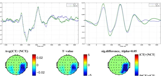
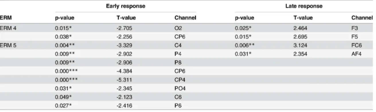
As we can see in Figure 4, the results showed the feasibility of the proposed method as a temporal segment selection strategy feature to increase multi-class classification

We instructed subjects to execute hand open/close, supination/pronation, and elbow extension/flexion movements according to cues presented on a computer screen, i.e., 6

Considering different DL architectures, we investigated deep neural network (DNN) modules, which are consists of several fully-connected layers; a proposed hierarchical DNN

Two conditions are simulated in this way while the amount of vertical dis- parity in one condition (3D-2) is 40 % less than the other condition (3D-3). The cube is presented to

The results confirm that our method is able to significantly reduce different types of artifacts like, e.g., high frequency muscle artifacts or low frequency artifacts caused by

The results confirm that our method is able to significantly reduce different types of artifacts like, e.g., high frequency muscle artifacts or low frequency artifacts caused by

Department of Mathematics, Imam Khomeini International University, Ghazvin, 34149-16818, Iran Reprint requests to S.. Some numerical results are given to demon- strate the validity

In this paper the hamotopy analysis method (HAM) is used for solving ordinary differential equations which arise from problems of the calculus of varia- tions.. This approach