P HOSPHORESCENT E MITTERS FOR OLED A PPLICATIONS
FROM S YNTHESIS TO P HOTODEGRADATION
Dissertation
Zur Erlangung des Doktorgrades der Naturwissenschaften (Dr. rer. nat.)
an der Fakultät für Chemie und Pharmazie der Universität Regensburg
vorgelegt von
Susanna Schmidbauer
aus Regensburg
2013
University of Regensburg.
Date of the Submission 14.02.2013
Date of the Colloquium 15.03.2013
Board of Examiners:
Prof. Dr. Jörg Daub (Chairman)
Prof. Dr. Burkhard König (1st Referee)
Prof. Dr. Kirsten Zeitler (2nd Referee)
Prof. Dr. Frank-Michael Matysik (Examiner)
Mein Dank gebührt meinem Promotionsbetreuer Prof. Dr. Burkhard König. Er ermöglichte mir die Mitarbeit an einem interessanten Industrieprojekt und nahm sich immer Zeit, wenn ich wissenschaftlichen Rat suchte. Ich danke ihm vor Allem für sein absolutes Vertrauen, das er mir bei der Koordination und Repräsentation unseres Teilprojektes entgegenbrachte.
Prof. Dr. Kirsten Zeitler danke ich für die Übernahme des Zweitgutachtens, Herrn Prof. Frank- Michael Matysik dafür, dass er als Drittprüfer eintritt und Prof. Dr. Jörg Daub für die Übernahme des Vorsitzes während meiner Prüfung.
Dem Bundesministerium für Bildung und Forschung (BMBF) danke ich für die Finanzierung meiner Promotion. Allen Konsortiumspartnern danke ich für die interessanten und unkomplizierten Projekttreffen. Ganz besonders gedankt an dieser Stelle ist Dr. Philipp Stößel, Dr. Dominik Joosten und Dr. Anna Hayer. Nicht nur ihre schnelle, unkomplizierte und verlässliche Unterstützung, ihre große Hilfsbereitschaft und Geduld in der Beantwortung OLED relevanter Fragen sondern auch das lustige und entspannte „social networking“ machten diese Zusammenarbeit für mich zu etwas Besonderem.
Andreas Hohenleutner danke ich für ein unbeschreibliches Jahrzehnt, das wir Seite an Seiter verbracht haben: eine tolle Abiturzeit, ein anstrengendes Studium (bezogen aufs Lernen als auch aufs Feiern), einen unglaublichen Forschungsaufenthalt in Indien, eine erfolgreiche und kollegiale Zusammenarbeit im Projekt und unvergessliche Momente inner- und außerhalb des Arbeitskreises. Mal sehen, was die Zukunft für uns bereit hält...
Ich danke der Abteilung Zentrale Analytik des Fachbereichs Chemie und Pharmazie der Universität Regensburg für die schnelle und saubere Ausführung sämtlicher Aufträge.
Dr. Rudolf Vasold danke ich ganz herzlich für seine Erfahrung und große Unterstützung, ohne die die Nutzung und Instandhaltung unseres „sensiblen Ungetüms“ nicht so einfach möglich gewesen wäre. Ja, Rudi, jetzt passt alles;)
Bei Britta Badziura, Simone Strauss, Ernst Lautenschlager, Dr. Petra Hilgers, Susanne Schulze und Viola Rappenberger bedanke ich mich für ihre Unterstützung in technischen und organisatorischen Angelegenheiten. Regina Hoheisel danke ich für ihre engagierte Art und schier unendlichen Geduld, sei es bei der Messung von CVs oder dem Versuch, das Café König nicht im Chaos untergehen zu lassen. Elisabeth Liebl danke ich für ihr unbeirrbares und temperamentvolles Engagement, das die ermüdete Bürokratie der Universität kurzzeitig immer wieder zu Rekordleistungsfähigkeit anspornte. Ich wünsche Ihnen einen wundervollen Ruhestand, vollgepackt mit nahen Radausflügen und fernen Reisen.
Ich danke Christoph Stanglmair, Stefanie Jäger, Melanie Hacker und Florian Hastreiter für ihre Mitarbeit an meinem Projekt im Rahmen von Forschungspraktika.
Auf jeden Fall will ich zum Ausdruck bringen, wie dankbar ich bin, Teil eines so wunderbaren Arbeitskreises zu sein. Kulinarische Besonderheiten wie Friday Lunch, Internationale Abende oder Kino-Nächte mit Schoko-Chili, aber auch die äußerst lehrreichen Konferenz-Besuche werde ich nie vergessen.
Meinen Laborkollegen Andreas Hohenleutner, Dr. Mouchumi Bhuyan, Christoph Stanglmair und Tamal Ghosh danke für eine gutes Arbeitsklima.
Den „alten Hasen“ Dr. Harald Schmaderer, Dr. Florian Schmidt, Dr. Robert Lechner, Dr.
Carolin Fischer, Dr. Daniel Vomasta, Dr. Tatiana Mitkina, Dr. Cristian Ochoa Puentes und Dr.
Carolin Ruß danke ich für eine herzliche Aufnahme in den Arbeitskreis und ihre Hilfe in allen möglichen Fragen.
Biers. Stefan Balk, Malte Hansen, Anna Eisenhofer, Stefan Troppmann, Thea Hering und Andreas Müller danke für unbeschreibliche Augenblicke am Lehrstuhl. Den beiden Peters Raster und Schroll danke ich für ihr ständiges Interesse am Stand meiner Forschung. Manuel Bause danke ich für seine ständigen Bemühungen den Lehrstuhl technisch immer auf dem neuesten Stand zu halten.
Maria Cherevatskaya, Thomas Zanni, Durga Prasada Rao Hari, Thamal Ghosh, Qui Sun, Dr.
Javier Bardagi, Michal Poznik, Dr. Supratim Banerjee, Claire de Nonancourt, I want to thank all of you so much for bringing new spirit in our group and spoiling us with delicious specialities.
Natascha Kuzmanovic danke ich für schöne Gespräche während den Kaffeepausen, ihren ewigen Enthusiasmus und ihre Fähigkeit, jeden mit ihrem Lachen mitreißen zu können.
Christian Ehrenreich danke ich für seine Hilfe in allen Bereichen ums Thema OLED, aber vor allem für seine angenehme, ruhige Art, die jeden den Stress vergessen lässt.
Allen meinen Freunden danke ich für eine unvergessliche Zeit inner- und außerhalb der Uni, inner-und außerhalb von Deutschland und Europa. Alina, Marion und Kathi, Euch danke ich für Eure jahrelange Freundschaft, und dass trotz mancher Durststrecken der Kontakt nie eingeschlafen ist. Ich hoffe, dass das noch lange so bleiben wird. Josef danke ich für viele lustige und grummlige (vor allem montags) Stunden. Tobi, mein Retter, ohne ihn hätte ich den Glauben an die „moderne Technik“ wohl schon vor dem Antritt meiner Promotion verloren! Hanni, danke für die zahlreichen verwirrenden Gesprächen (der Puzzle-Tee Abend steht auf jeden Fall auf meiner To-do-Liste für den Ruhestand;). Doris, die Zeit mit dir in Mexiko war einfach super. Sanne danke ich, dass sie sich entschlossen hat, nach Regensburg zu kommen und dass ihre wortreiche Natur Montag früh um 6 auch noch geschlummert hat. Daniel, danke für ausgefallene Erlebnisse und Genüsse überall auf der Welt. Petr, danke für lustige Abende in Deiner Wohnung - auch wenn ich Dir für den Kanister-Fusel nicht dankbar sein kann… Sabrina, danke für unsere tolle Zeit als Wohngemeinschaft; meine Selbstgespräche vor dem Fernseher waren eine interessante Erfahrung. Andi K., danke für die letzten 10 Jahre, die wir gemeinsam durchlebt und durchfeiert haben. Seppi, Hermann, Andi P., danke dass ich mit euch Berlin in allen Facetten erleben durfte. Caro, danke dass du mir so eine gute Freundin geworden ist, und dass das auch über die Weltmeere erhalten bleibt. Paul – einfach danke für alles!
Claudia, Bäda, allen (ehemaligen) Mitarbeitern und meinen langjährigen Stammgästen der Oma Plüsch danke ich für ihre große Unterstützung. Ihr habt es immer geschafft, mich auf andere Gedanken zu bring. Und natürlich Tom: du warst der tollste Chef, den man sich wünschen kann.
Meiner Familie gebührt ein ganz besonderer Dank: Meinen Eltern danke ich für ihr Vertrauen, ihre Hilfe und ihre Liebe. Danke, dass Ihr mir alle Freiheiten und Möglichkeiten eröffnet habt, die für mich wichtig waren. Meiner Schwester danke ich für ihre große Unterstützung. Ich bin froh, dass ich Dich habe. Meinen Großeltern danke ich für alles, was sie für mich getan haben. Dem ganzen Rest meiner Familie danke ich für die tollen Familientreffen. (Alle Namen zu nennen würde den Rahmen der Arbeit sprengen, aber Onkel Michael, derjenige, der mir meine eigene Doktor-Weiße braut muss auf jeden Fall ein Plätzchen in diesem Absatz finden.) Eine bessere Familie wie Euch kann man sich nicht wünschen!!
Zuletzt will ich Dominik danken, für seine Unterstützung, seinen Ansporn, seine aufbauenden Worte, seine Überraschungen, sein Verständnis.
Danke, dass Du Du bist… dass Du da bist… dass Du mein bist…
I NTRODUCTION 1
C HAPTER 1 9
CHEMICAL DEGRADATION IN ORGANIC LIGHT-EMITTING DEVICES:MECHANISMS AND IMPLICATIONS FOR THE DESIGN OF NEW MATERIALS
1. Introduction 11
2. Possible Reasons for Defect Formation 12
2.1 Charge Carrier Induced Degradation 12
2.2 Exciton Induced Degradation 13
3. Useful Techniques for the Elucidation of Chemical Degradation Mechanisms 14
3.1 Chemical Analysis Techniques 15
3.2 Theoretical Calculations 15
4. Chemical Degradation Mechanisms in OLEDs and Strategies for Stability
Improvement 16
4.1 Degradation of Hole Conducting Materials 16
4.2 Degradation of Electron Conducting Materials 22
4.3 Strategies for the Stability Improvement of Transport Materials 27
4.4 Degradation of Phosphorescent Emitters 29
4.5 Strategies for the Stability Improvement of Phosphorescent Dopants 34
5. Conclusion 36
6. References 37
C HAPTER 2 41
RAPID COMBINATORIAL SYNTHESIS AND CHROMATOGRAPHY BASED SCREENING OF PHOSPHORESCENT IRIDIUM COMPLEXES FOR SOLUTION PROCESSING
1. Introduction 43
2. Results and Discussion 44
2.1 Synthesis 44
2.2 Screening 47
2.3 Separation and Spectroscopic Properties 48
2.4 Photodegradation Studies 51
3. Conclusions 53
4. Experimental 54
4.1 Methods and Materials 54
4.2 Photodegradation Studies 55
4.3 Syntheses 55
5. References 58
C HAPTER 3 61
NEW APPROACHES TOWARDS COMBINATORIAL DERIVATIZATION OF IR(PPY)3
1. Introduction 63
2. Results & Discussion 64
2.1 C-O Coupling Reactions 64
2.2 C-C Coupling Reactions 68
3. Conclusions 69
4. Experimental 70
4.1 Methods and Materials 70
4.2 Syntheses 70
5. References 72
C HAPTER 4 73
STUDIES ON THE PHOTODEGRADATION OF RED,GREEN AND BLUE PHOSPHORESCENT OLEDEMITTERS
1. Introduction 75
2. Results and Discussion 76
2.1 General Observations 77
2.2 The Influence of Halogenated Solvents 78
2.3 The Influence of Oxygen 80
3. Conclusions 86
4. Experimental Part 87
4.1 Methods and Materials 87
4.2 Photodegradation Studies of the Liquid Samples 87
4.3 Photodegradation Studies of the PMMA Substrates 88
5. References 88
C HAPTER 5 91
PT-COMPLEXES OF TETRADENTATE LIGANDS FOR OLED-APPLICATIONS
1. Introduction 93
2. Results and Discussion 96
2.1 Synthesis 96
2.2 X-ray Crystal Structure 97
2.3 Spectroscopic Properties 98
2.4 Electrochemical Properties 100
2.5 Photodegradation 101
2.6 Device Performance 102
3. Conclusions 104
4. Experimental 105
4.1 Experimental Methods and Materials 105
4.2 Photodegradation Studies of the PMMA Substrates 106
4.3 SYNTHESES 107
6. References 115
S UMMMARY 117
Z USAMMENFASSUNG 121
A PPENDIX 125
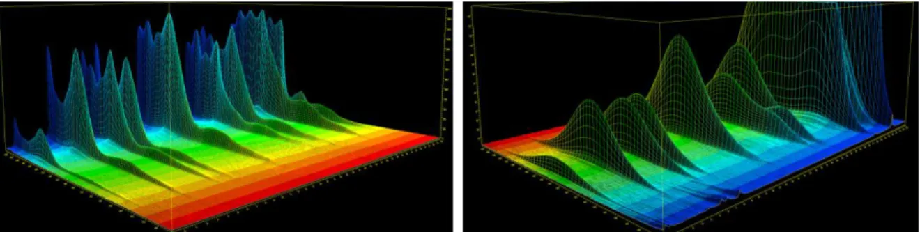
1. Supporting Information of Chapter 2 126
1.1 3D-Absorption- and Emission-Plots of Library 1, 3 and 4 126
1.2 Absorption and Emission Spectra 127
1.3 Photodegradation Plots 131
1.4 Picture of the Irradiation Unit 135
2. Supporting Information of Chapter 3 136
3. Supporting Information of Chapter 4 137
3.1 Reproducibility of the degradation studies in toluene under
ambient conditions 137
3.2 Reproducibility of the degradation studies in a PMMA matrix under
ambient conditions 137
3.3 Degradation curves of Ir(piq)3, Ir(ppy)3, Ir(Me-ppy)3 and Ir(F,CN-ppy)3
in CH2Cl2 under ambient and inert conditions 138 3.4 Degradation curves of Ir(piq)3, Ir(ppy)3, Ir(Me-ppy)3 and Ir(F,CN-ppy)3
in benzene and toluene under ambient and inert conditions 138
4. Supporting Information of Chapter 5 139
4.1 Absorption Spectra of the Ligands 5a,b and 5’a-c in Comparison
with the Corresponding Complex Spectra 1a,b and 1’a-c 139
4.2 1H- and 13C-NMR Spectra 140
5. Abbreviations 153
6. Curriculum Vitae 156
7. List of Presentations and Publications 157
I NTRODUCTION
O
RGANICL
IGHTE
MITTINGD
IODES– B
ASICSC
ONCERNINGD
EVICES
ETUP&
W
ORKINGP
RINCIPLEO
VERVIEW OF THIST
HESISAt least since 1987 when the first operating multilayer organic light-emitting diode (OLED) was realized in the laboratories of the Eastman Kodak company,[1] this technology drew the research interest of scientists all over the world. Till now the competition on the industrial market has exacerbated more and more. Finally, in 1997, the first commercial OLED display was introduced by the Pioneer Corporation, utilized in a car radio.[2] Applications in mobile phones, digital cameras and TVs followed. In 2008, OSRAM tapped a new market for that technology – the lighting industry – by presenting the world’s first OLED lamp.[3] According to the media, the field of application - and the creativity to design new gadgets - seems to be endless: luminescent wallpapers,[4] rollable notebooks[5] or MP3-bracelets,[6] just to name a few. Data-eye-glasses with bidirectional OLED microdisplays, developed at the Frauenhofer IPMS in Dresden, were awarded on the display conference of the Society for Information Display (SID) 2012.[7] Despite all the enthusiasm, having a real chance to become market-leader in any field, there are still some deficiencies that have to be overcome. One of them is the only moderate lifetime for most of the devices. To have a closer look into this special problem, first of all, general questions concerning device setup and the basic processes resulting in their entirety in light emission will be discussed briefly.[8]
Device Setup
An OLED consists of an organic layer sandwiched between a cathode and an anode. The latter is placed on a transparent substrate like glass or foil. The organic layer comprises different materials exhibiting charge transporting and light emitting properties, respectively (Figure 1).
Figure 1. General setup of an organic light-emitting diode.
Charge Injection
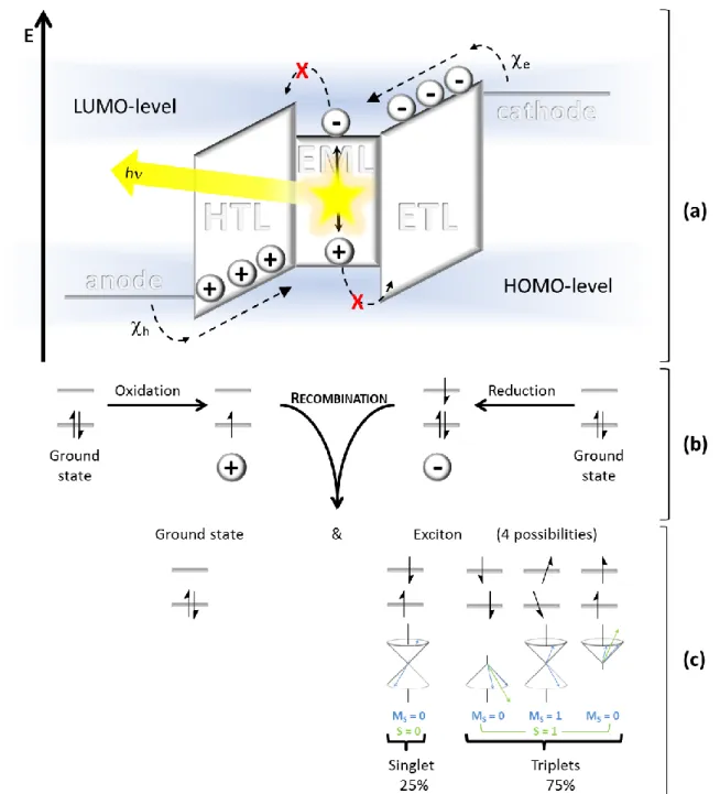
Applying voltage to the device, the anode injects negative charge carriers (electrons) into the electron transport layer (ETL). More detailed, electrons are transferred in the lowest unoccupied molecular orbital (LUMO) of the electron transport material, which is formally reduced to a radical anion (Figure 2a, b). Injection of positive charge carriers (holes) into the hole transport layer (HTL) via the cathode proceeds analogously: an electron is withdrawn from the highest occupied molecular orbital (HOMO) of the hole conducting material, which is therefore oxidized to a radical cation.
The energy difference between the Fermi level of the anode (cathode) and the LUMO (HOMO) of the electron (hole) transporting material results in an injection barrier e h). To guarantee a balanced charge carrier injection, these barriers must be comparable. Lower
h ande values allow for an easier charge injection. Thus lower initial driving voltages are required, which can have beneficial effects on device lifetimes.
Charge Transport
Charge carrier transport proceeds according to the electric field through the HTL and ETL towards the emitting layer (EML) in between. This movement is postulated as hopping process,[9] which is formally the sum of subsequent redox reactions: the reduced electron transporting molecule transfers its additional electron to the LUMO of an adjacent molecule under re-oxidation. The hole transport proceeds vice versa.
Charge Recombination & Light Emission
When an electron and a hole get in close proximity to each other, Coulomb interactions lead to charge recombination yielding a ground state molecule and an excited, uncharged biradical molecule, the exciton (Figure 2c). Due to different spin-orientations, four configurations are possible. The antiparallel spin-orientation gives a singlet exciton, whereas diverse parallel spin-orientations yield three different triplet states. Thus, the ratio of singlet to triplet excitons is 1 to 3. According to Kasha’s rule, relaxation to the ground state proceeds exclusively from the lowest excited state. If molecules reach higher energy levels, a radiationless relaxation to this state takes place (internal conversion, IC).
Figure 2. (a) Energy diagram of a multilayer OLED device under applied voltage: Anode|hole transport layer (HTL)|emission layer (EML)|electron transport layer (ETL)|cathode; h: hole injection barrier from the anode to the HOMO of the HTL; e: electron injection barrier from the cathode to the LUMO of the ETL. Charge-( , ) injection, transport and recombination, resulting in light emission, are depicted. (b) Charge transport is a formal oxidation (hole transport) or reduction (electron transport) of the appropriate conducting material. (c) Charge recombination results in the formation of a ground state molecule and an exciton with one of 4 different spin-orientations. The quantum number of the spin angular momentum (S) and its z-component (Ms) for the singlet and triplet states are included.
Pure organic compounds can only relax radiatively (fluoresce) to the ground state from the singlet excited state S1 (Figure 3). Such a process is spin forbidden for the first triplet excited state T1. Therefore, all triplet excitons (75% of the formed excitons) decay non-radiatively.
That’s why organic compounds do not exceed quantum efficiencies of 0.25 in organic light-emitting devices. In order not to lose the largest amount of the available energy, transition metal complexes are used as emitters in organic light-emitting devices. Due to the strong spin-orbit coupling of the heavy atom (usually Ir, Pt) the emissive decay from the T1-state (phosphorescence) becomes partly allowed and a fast and efficient transition from the singlet to the triplet excited state under spin conversion (intersystem crossing, ISC) takes place, the so-called triplet-harvesting effect. Using this strategy, significantly higher quantum yields can be achieved compared to fluorescent dyes.
Figure 3. Jablonski diagram depicting the electronic transitions possible after excitation (S0→ S1):
internal conversion (IC), intersystem crossing (ISC) and fluorescent (S1→ S0), phosphorescent (T1→ S0) as well as non-radiative decay.
In phosphorescent OLEDs, the emission layer usually consists of an appropriate organic matrix material (host) which is doped with organometallic emitters (guests). For an efficient phosphorescent emission, excitons formed on the matrix molecules must diffuse within the emitting layer to the dopants. This can proceed via two different energy transfer mechanisms, the Foerster or the Dexter transfer (Figure 4). The dipolar Foerster transfer proceeds between a singlet excited donor molecule (host) and an acceptor molecule (guest) in the ground state, reaching distances of several nanometers. A spectral overlap between donor-emission and acceptor-absorption is mandatory. In contrast, the Dexter transfer is an electron exchange process, only possible for neighboring molecules. In this case, an excited electron from the LUMO of a donor-molecule is transferred to the LUMO of a ground state acceptor-molecule. In exchange, an electron from the HOMO of the latter
is transferred to the HOMO of the host. This is not only possible for singlet but also for triplet excited molecules. For an efficient transfer, the exciton energy of the donor molecule should be higher than that of the acceptor molecule.
Figure 4. Foerster and Dexter transfer mechanisms between excited host (H*) and ground state guest (G) molecules.
Overview of this Work
Altogether, many different processes are involved in the light emission of OLEDs. Only a perfectly fine-tuned interplay of all these mechanisms results in a proper device performance which is mandatory for the successful commercial application.
Meanwhile, most of the error sources leading to device deterioration, like the formation of dark spots or the occurrence of electrical shorts are well understood and can be prevented by optimizing the device architecture and encapsulation. The intrinsic degradation, in contrast, leading to a slow but steady luminance decrease with the operation time, constitutes a more serious challenge. Chemical reactions are suspected to cause this type of degradation. Chapter 1 reviews recent advances in this research field.[10]
Elucidated degradation products and mechanisms of all types of (metal)organic materials present in an OLED device are summarized, their commonalities are highlighted and resulting implications on the material design are stated. But especially for the phosphorescent emitters no reliable guidelines for the prediction of their stabilities can be provided to date. Also important spectroscopic factors like luminescence efficiencies or color purity can’t be assessed theoretically yet. Thus, the discovery of new promising emitters for OLED application still follows the trial and error strategy via synthesizing and evaluating complexes individually.
In order to overcome this time-consuming approach, we developed a methodology, which combines the combinatorial derivatization of iridium complexes with a chromatography based screening setup.[11] This useful tool allowed us to characterize several complex libraries and to identify interesting photophysical and photochemical effects induced by different substitution patterns (Chapter 2). The structural diversity in the complex libraries was accomplished by combinatorial C-C and C-N coupling reactions on a bromo-functionalized Ir(ppy)3-precursor. In order to expand the pool of possible reaction
1H* 1G 1H 1G*
FOERSTER-TRANSFER
E
1H* 1G 1H 1G*
S1-S1 DEXTER-TRANSFER
E
3H* 1G 1H 3G*
T1-T1 DEXTER-TRANSFER
E
pathways applicable for the combinatorial approach, investigations on suitable reaction conditions for C-O couplings were studied in Chapter 3.
Interesting observations from the second chapter concerning the influence of structural changes on the degradation behavior of these complexes prompted us to study the degradation behavior of some red, green and blue emitting iridium complexes.[12] A detailed discussion on the results is given in Chapter 4.
The last chapter reports about the synthesis and photophysical characterization of a new class of cyclometalated platinum(II)complexes for the application in OLEDs.
References
[1] C. W. Tang, S. A. VanSlyke, Appl. Phys. Lett. 1987, 51, 913-915.
[2] http://pioneer.jp/corp/profile-e/history/, access date: 11/1/2013.
[3] http://www.oled-info.com/history-page-2, access date: 11/1/2013.
[4] http://globonsomeday.blogspot.de/2010/02/oled-wallpapers-could-make-light- bulbs.html, access date: 11/1/2013.
[5] http://gadget-demo.blogspot.de/2010/01/rolltop-laptop-from-future.html, access date: 11/1/2013.
[6] http://pinterest.com/netizenpros/flexible-oled-gadgets/, access date: 11/1/2013.
[7] http://www.printedelectronicsworld.com/articles/data-eye-glasses-based-on- bidirectional-oled-microdisplays-00004497.asp, access date: 11/1/2013.
[8] M. Rothmann, Ph. D. Thesis, Universität Bayreuth, GER, 2009, http://nbn- resolving.de/urn/resolver.pl?urn:nbn:de:bvb:703-opus-6946.
[9] O. Nuyken, S. Jungermann, V. Wiederhirn, E. Bacher, K. Meerholz, Monatsh. Chem.
2006, 137, 811-824.
[10] S. Schmidbauer, A. Hohenleutner, B. König, Adv. Mater. accepted.
[11] A. Hohenleutner, S. Schmidbauer, R. Vasold, D. Joosten, P. Stoessel, H. Buchholz, B.
König, Adv. Funct. Mater. 2012, 22, 3406-3413.
[12] S.Schmidbauer, A. Hohenleutner, B. König, submitted.
╪ Andreas Hohenleutner and Susanna Schmidbauer were contributed equally to this work.
C HAPTER 1
C
HEMICALD
EGRADATION INO
RGANICL
IGHT-E
MITTINGD
EVICES: M
ECHANISMS ANDI
MPLICATIONS FOR THED
ESIGN OFN
EWM
ATERIALS╪Degradation of the materials in organic light-emitting devices (OLEDs) is the major impediment for the development of economically feasible, highly efficient and durable devices for commercial applications. Even though this chemical degradation is complex and the least understood of the different degradation modes in OLEDs, scientists were successful in providing insight into some of the responsible processes. In this progress report we will review recent advances in the elucidation of chemical degradation mechanisms:
First possible reasons for defect formation and the most common and important methods to investigate those processes are covered before discussing the reactions and their products for the different types of materials present in a device. We summarize commonalities in the occurring mechanisms, and identify structural features and moieties that can be detrimental to operational stability. Some of the resulting implications on the development of new materials are presented and backed by concrete examples from literature.
1. I
NTRODUCTIONFrom the first discovery of light emission from anthracene single crystals in 1965,[1] organic electroluminescence has developed into a field of immense research interest with hundreds of groups around the world working to improve materials and devices. While it initially did not get much scientific attention, the first heterojunction device by Tang and Van Slyke in 1987[2] sparked academic and commercial interest in the subject and the advances in the efficiency of organic light-emitting devices since then have been tremendous. In particular the discovery of the triplet harvesting effect by Baldo et al. was responsible for a leap in the internal quantum efficiencies of the devices, enabling the conversion of nearly 100% of the charge carriers into photons.[3] As the recombination of electrons and holes yields triplet (75%) and singlet (25%) excitons and organic materials are usually only capable of emission from singlet states (fluorescence) this used to limit the achievable internal quantum efficiency. Using phosphorescent transition metal complexes as the emitting materials could overcome this limitation. Emission of light takes place from the triplet states of these compounds and singlet excitons are rapidly converted into triplets via efficient intersystem crossing (ISC). By now, organic light-emitting devices have made their way into mass production for display applications and are also expected to find application in the commercial lighting market in the near future. Besides high efficiencies and low power consumptions, it is also important that the devices have a high operational stability. Degradation in OLEDs can be caused by the formation of dark spots, the occurrence of electrical shorts leading to a sudden decrease in luminance (catastrophic failure) or intrinsic degradation. Dark spot formation and catastrophic failure can be suppressed by carefully optimized and controlled fabrication conditions and an adequate encapsulation of the devices and thus are no longer considered an obstacle for commercial applications. Intrinsic degradation is characterized by the decrease of overall luminance over time during continuous driving. This is accompanied by a rise of the operating voltage necessary to maintain operation at a constant current. This type of degradation is believed to result mainly from the deterioration of organic (and in some cases metal-organic) molecules in the device. The location and nature of this chemical degradation is highly dependent on the employed materials as well as the device structure
and the occurring processes can be manifold even for a single device. It is due to this complexity that chemical degradation is still the least understood of the different modes of degradation. To enable the development of new materials with high performances and stabilities however, it is important to understand the chemical nature of defects in the organic layers and the reactions that lead to their formation.
In this progress report, we will try to shed light on the chemistry behind intrinsic degradation in OLEDs by giving an overview on recent advances in the elucidation of chemical degradation mechanisms, how they can be investigated and how the gained knowledge can impact the design of new materials. It is not our aim to present a comprehensive review about intrinsic degradation and operational lifetimes, which would include many aspects of device engineering and go beyond the scope of this manuscript, but rather to limit our discussion to the chemical aspects of device degradation. Nevertheless, to provide a basis for the understanding of the processes, we have to discuss some of the physical mechanisms responsible for the formation of defect sites in OLEDs.
2. P
OSSIBLER
EASONS FORD
EFECTF
ORMATIONIn general it is believed that intrinsic device degradation is caused by the chemical conversion of a fraction of molecules in the organic layers of the device. The degradation products can then act as non-radiative recombination centers, luminescent quenchers or deep charge traps. Luminance loss can be caused by the former two or, if the emitting dopant itself is destroyed during device operation, simply by the lack of emitting centers.
Deep charge traps are sites that can “trap” an electron or hole due to suitable energy levels and thus cause a localization of charges at the defect sites. Accumulation of these immobilized charges then leads to a rise of the operating voltage. It should be noted that a single defect site is not necessarily limited to one of the mentioned roles but might in fact act as an electron- and hole-trap as well as a quenching site at the same time. The formation of these defects can be caused by different processes and proceed via a variety of possible pathways.
2.1 Charge Carrier Induced Degradation
Instability of the molecules corresponding radical cations or radical anions can lead to defect formation by bond rupture or via radical reactions with surrounding molecules. The degradation is in this case caused by the holes and electrons moving through the organic materials and can thus be labeled charge carrier induced degradation. In efficient, state- of-the-art OLEDs, chemical degradation in the bulk of the transport layers - that is not in the vicinity of the emitting layer - is likely to be of this origin. The formed defects can act as
traps for the charges moving through the device and should in general mainly result in a rise of the operating voltage.
2.2 Exciton Induced Degradation
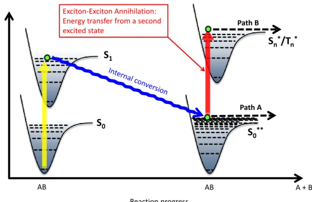
Due to the presence of excitons, the situation is a bit more complex in the emitting layer and at its interfaces with the adjacent transport or blocking layers. Excitons can participate in defect formation either via direct degradation of molecules in the excited state or via bimolecular quenching reactions.[4] Destructive deactivation can occur via direct excitation to a repulsive potential or via thermal population of higher lying dissociative states of a molecule. These dissociation processes can produce charged fragments or radicals that can in turn react with surrounding molecules and thus lead to deterioration of the organic or metal-organic materials. Bimolecular annihilation reactions involving excitons constitute another pathway.[4-7] The annihilation of two excitons leads to the population of higher lying excited states that can undergo further reactions via two possible pathways: direct dissociative processes similar to the ones induced by normal excitonic degradation or degradation via the so called “hot molecule mechanism”
(Figure 1). In this case, internal conversion from an excited singlet state gives a highly vibrationally excited electronic ground state S0**.[8] This “hot molecule” has an equivalent vibrational temperature of 2000-4000 K and can dissociate directly (path A) or via excitation by another photon (or energy transfer from another exciton, path B). The absorption bands of these hot molecules show a thermal broadening causing an enhanced absorption at lower energies.
Energy transfer from an exciton to a polaron (radical cation or anion) yields a polaron excited state (excited radical) that might decay via similar pathways.[9-10] The importance of this particular route is highlighted by the fact that exciton-polaron annihilation has even been proposed to be the dominant mechanism for different phosphorescent devices.[10]
Figure 1. The “hot molecule” mechanism. Internal conversion from an excited singlet state gives a highly vibrationally excited electronic ground state S0**. This “hot molecule” can dissociate directly or via excitation by another photon (or energy transfer from another exciton).
3. U
SEFULT
ECHNIQUES FOR THEE
LUCIDATION OFC
HEMICALD
EGRADATIONM
ECHANISMSPhysical methods can provide information on the amount and location of trapped charges, luminescence quenchers and non-radiative recombination sites and often also on the electronic/(photo)-physical processes leading to their formation. However, they usually do not allow to draw conclusions regarding their chemical nature.
Since the organic layers in an OLED device are typically only several nm thick, the material available for analysis is usually very limited. The actual degradation products will only amount to a small fraction of the material even after extended operation. A defect density of 0.1% in the emission layer for example can already lead to 50% loss in luminance.[4]
Considering the likely participation of different pathways and their mostly radical nature, the degradation of OLEDs is furthermore expected to lead to a multitude of deterioration products rather than to a single potentially easily identifiable one. The elucidation of chemical degradation mechanisms and products therefore presents a significant challenge.
Exciton-Exciton Annihilation:
Energy transfer from a second excited state
Reaction progress
A + B
S
1S
0S
0**S
n*/T
n*Path B
Path A E
AB AB
3.1 Chemical Analysis Techniques
However, there are many reports on the chemical analysis of OLEDs and a number of techniques that have proven useful in gaining insight on the chemical deterioration products and pathways. Spectroscopic methods can provide information on the electronic and chemical structure of degradation products. Techniques that have been employed include UV-Vis, infrared, nuclear magnetic resonance as well as electron paramagnetic resonance spectroscopy.[11-15] Nonetheless, to gain detailed structural information from these methods, isolation of the degradation products from the bulk material is usually necessary. With the limited amount available, this represents a significant impediment. High performance liquid chromatography (HPLC) is a technique that allows the analysis and separation of complicated mixtures and the detection of very small quantities of materials. It can additionally be supplemented through above mentioned analysis methods to successfully identify degradation products.[11] HPLC and its combination with mass spectrometry (HPLC-MS) has been employed successfully to investigate degradation pathways in organic light-emitting devices for example by comparing chromatogram peaks and the corresponding ions of pristine and aged devices.[11, 16-17] While most chemical analysis techniques require dissolving the organic layers of the device before the measurements, mass spectrometry using a laser desorption/ionization (LDI) source is a powerful method for the direct analysis of organic thin films and even fully processed OLED devices. The molecules of a solid sample are ionized and accelerated via excitation with a UV-laser pulse in a strong electric field inside a vacuum chamber. This ionization mode traditionally requires preparation of the analytes within a suitable matrix material to enable excitation and ionization of the materials (MALDI: matrix-assisted laser desorption/ionization). An OLED device however presents an ideal LDI sample in itself and can thus be analyzed directly. The combination of electron accepting (electron transport layers/n-dopants) and electron donating (hole transport layers/p-dopants) properties together with the strong UV-absorption of most organic OLED materials enable an efficient excitation, desorption and ionization of the sample. The high sensitivity of the LDI method facilitates the detection and identification of degradation products even as trace impurities and has enabled the elucidation of a variety of chemical degradation pathways.
3.2 Theoretical Calculations
Quantum chemical calculations are a popular tool for the prediction of properties of molecules and materials in their ground and excited states, the elucidation of chemical and photochemical reaction pathways and the interpretation of experimental results.
Especially density functional theory (DFT) calculations have become a standard tool in the development of new materials for organic electronics. Computational chemistry can help
to assess the feasibility of reaction pathways that molecules can undergo. Energies and geometries of the participating electronic states and reaction intermediates can be predicted and thus contribute to the understanding of charge and exciton induced processes in the organic materials. Calculations have for example been employed to identify “structurally weak” parts of molecules by determining bond dissociation energies or to identify deactivation routes and possible exciton induced degradation pathways for phosphorescent emitters.
4. C
HEMICALD
EGRADATIONM
ECHANISMS INOLED
S ANDS
TRATEGIES FORS
TABILITYI
MPROVEMENTWith the different processes leading to the formation of degradation products and defect states, respectively, in combination with the variety of materials present in a typical device, it is likely that not only one pathway is responsible for the OLED instability. It is the sum of all degradation events in the different layers leading to device failure. Therefore even minor instabilities in the materials have to be elucidated and eliminated to ensure highly efficient and durable OLED devices. In the following sections we will review the degradation behavior of some materials that were investigated until now, trying to identify (re)occurring mechanisms starting with the hole conducting, followed by the electron conducting materials and ending with phosphorescent emitters. Not only the pure degradation mechanisms are summarized, but also some concluding remarks are drawn for rational changes in the molecule structures, which might lead to an improvement in device stability.
4.1 Degradation of Hole Conducting Materials
Aromatic amines are widely used in organic light-emitting diodes due to their physical and electrochemical properties. They are a well investigated class of molecules for the use as hole transporting, electron blocking as well as host materials in phosphorescent devices.
Much effort has been expended so far to shed light on the behavior of aromatic amines in driven OLEDs. Investigations showed that aromatic amines in the HTLs do not suffer any chemical degradation in single-carrier devices (electron- and hole-only devices, respectively). It was also observed that degradation mainly occurs in the vicinity of the HTL/EML-interface, where recombination and therefore exciton formation takes place. Both facts infer that aromatic amine degradation is mainly caused by excited states rather than charge carriers.[8, 14] Estimating the bond dissociation energies of several arylamines via DFT calculations provided some indications about the nature of the degradation
110 kcal/mol whereas C-N bond energy-levels are at least ~30 kcal/mol lower (Figure 2) and lie therefore in the same energy range as the first singlet excited state of the arylamines. The vulnerability of arylamines might consequently lie in the high probability of C-N bond dissociation in excited molecules.
Figure 2. Dissociation energies of different bond types in the hole condcuting materials NPB, TAPC and CBP.
Kondakov et al. assumed that the C-N bond cleavage is of homolytic rather than heterolytic nature due to the endothermicity of the latter.[14] The so generated reactive radical species undergo unselective subsequent reactions with adjacent neutral molecules resulting in long-lived -conjugated radical species. Due to their lower lying LUMO, energy transfer from the excited matrix or dopant molecules can occur. The very low oscillator strength of the following transition leads to the non-emissive character of these excited states. Thus, the formed radicals can not only act as deep and irreversible carrier traps but also as luminescence quenchers.[11] With respect to the chemical degradation pathway, these radicals can additionally undergo hydrogen transfer, disproportion or radical addition reactions with a neighboring radical to form neutral, saturated degradation products (Scheme 1).
Several groups successfully analyzed different aged OLED devices via HPLC/MS techniques. By this means, degradation products derived from C-N bond dissociation and following reactions could be identified for a variety of arylamines, thus supporting the proposed general degradation pathway. Some of these products and more details and peculiarities of the mechanism will be discussed in the following section.
60 70 80 90 100 110 120
Bond Dissociation Energy / kcal/mol
C(sp2)-C(sp2)
S1energy range
NPB TAPC CBP
C(sp2)-C(sp2)
C(sp3)-C(sp3) C-N
C-N C(sp3)-C(sp2)
Scheme 1. General degradation pathway of aromatic amines in driven OLED devices.
The unequivocally identified degradation products of the host material CBP (4,4'- bis(carbazol-9-yl)biphenyl) are shown in Figure 3.[11, 14] Three different species (BPC, C and 3-CCBP), derived from C-N bond cleavage and subsequent reactions, could be isolated from aged OLED devices via HPLC separation. After 4000 h of operation at 40 mA/cm2 (LT50 = 80 h), approximately 20% of CBP had degraded. The main degradation product formed was BPC (about 1/3 of the degraded CBP molecules). The yields of the remaining two derivatives were much lower. Gel permeation chromatographic (GPC) analysis also revealed the presence of high-molecular-weight products.
Figure 3. Host material CBP and degradation products C, BPC and 3-CCBP identified by Kondakov et al.
In the carbazole-containing matrix material TCTA (4,4',4"-tris(carbazol-9-yl)triphenylamine) bond cleavage does not affect the carbazolyl moiety, but the central triphenylamine core (Figure 4, top).[16, 19] Sivasubramaniam et al. could also identify [TCTA-carbazole]-fragments in MS investigations in minor amounts, but these could be attributed to degradation processes during thermal vapor deposition.[20]
Figure 4. Degradation behavior of the arylamines TCTA, NPB, and spiro-TAD. Top: weak bonds of the molecules, which are responsible for degradation due to bond dissociation. Middle: identified degradation products of TCTA, resulting from substitution reactions with fragments of other TCTA molecules or of the adjacent material NPB. Bottom: identified degradation products of NPB, resulting from bond dissociation and substitution reactions of these moieties with neighboring NPB molecules.
Different mechanisms for the formation of these products have been proposed: Leo et al.
assumed a heterolytic dissociation of the C-N bond, yielding a cationic amine species and a phenylcarbazole anion, which reacts in a nucleophilic substitution with adjacent TCTA
molecules to TCTA+PC. In contrast, Sivasubramaniam et al. postulated a radical pathway for the formation of this product.[16] Additionally, miscellaneous substitution products with moieties of the adjacent hole transport material NPB (N,N'-bis(naphthalen-1-yl)-N,N'- bis(phenyl)-benzidine, degradation behavior discussed below) could be identified (Figure 4, middle).
In mass spectrometric investigations Leo et al. found that the electron blocking material spiro-TAD (2,2',7,7'-tetrakis(N,N-diphenylamino)-9,9-spirobifluorene) undergoes an analogous dissociation between the spiro-bifluorene core and the diphenylamine (Figure 4, top).[19]
Quantum chemical calculations on the hole transport material NPB revealed that the numerous non-equivalent C-N bonds have almost identical bond dissociation energies, which explains the multitude of different degradation products that could be detected for this material. Products NPB-NPA, NPA and N (Figure 4, bottom) could be unambiguously identified.[18] Further derivatives, lacking a phenyl (NPB-P) or naphthyl (NPB-N) moiety respectively, can be assumed according to mass spectrometric analysis of the degraded device, [20-21] as well as products formed by radical attacks (NPB+N, NPB+P).[18]
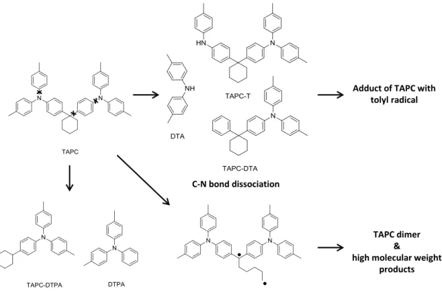
Investigating the degradation behavior of the hole transport material TAPC (di-[4-(N,N- ditolyl-amino)-phenyl]cyclohexane), Kondakov et al. did not only identify the expected C-N bond dissociation and resulting substitution products of TAPC (DTA, TAPC-T and TAPC-DTA, Figure 5).[18] Species like TAPC-DTPA and DTPA could be observed, which obviously originate from C-C bond cleavage. This is also reasonable keeping in mind that the dissociation energies of bonds containing C(sp3) centers are about 30 kcal/mol lower than these of double bonds, therefore having equal energies as the first singlet excited state of TAPC (Figure 2). Another degradation route, specific for molecules incorporating saturated rings, starts with the homolytic cleavage of C(sp3)-C(sp3) bonds. Due to the ring structure not two radicals are formed, but one single biradical which can easily undergo dimerization or polymerization reactions to high-molecular-weight compounds. The enormous increase of driving voltage in aged devices containing TAPC additionally suggests the accumulation of trapped charges in the bulk of the TAPC layer. This indicates that degradation not only occurs via excitons at the vicinity of the HTL/EML interface, but is at least partly caused by charge carriers, following a still unidentified degradation pathway.
Figure 5. Different pathways of TAPC-degradation: low dissociation energies of C-N, C(sp3)-C(sp3)- and C(sp2)-C(sp3) bonds lead to miscellaneous degradation products.
In terms of stability, interesting effects could be observed for CBP derived materials, which are related to the planarity and -conjugation of the molecules (Figure 6).[19, 22] DMFL-CBP follows a similar degradation pathway as CBP, namely C-N bond cleavage. In contrast, the 3,3’-methylated CDBP, predominantly degrades via C-C bond dissociation. Choi et al.
explained this observation based on the dihedral angles of the molecules.[22] While DMFL-CBP has a planar structure, CBP and CDBP are twisted with torsion angles of 35° and 90°, respectively. In the latter configuration, having the two phenyl groups perpendicular to each other, the -conjugation of this molecule is broken. This results in a decreased C-C bond dissociation energy and as a result in an increased likelihood of bond-cleavage.
Figure 6. Substitution induced torsion of tetra(aryl)benzidenes and resulting changes in bond strengths for DMF-CBP and CDBP.
C-N bond dissociation
C(sp2)-C(sp3) bond dissociation C(sp3)-C(sp3) bond dissociation
Adduct of TAPC with tolyl radical
TAPC dimer
&
high molecular weight products
Low et al. showed additionally that methylation in 2,2’- or 3,3’-position of the biphenyl core in tetra(aryl)benzedenes leads to increased oxidation potentials.[23] This effect seems to result from the non-planarity of the system - and therefore the restricted conjugation between the two phenyl moieties and the lone pairs of the nitrogen - caused by the sterical hindrance of the methyl substituents (Figure 6). Rigidification of the biphenyl moiety leads to an extended -conjugated system and a decreased oxidation potential. It is known that the oxidation potentials can be directly correlated to the ionization potentials of the materials. Adachi et al. proposed a linearity between the ionization potential and device lifetime and explain this with low initial driving voltages of devices incorporating easily ionizable hole transport materials.[24] Several groups demonstrated in experimental and theoretical investigations a linear dependence of the ionization potential and the Hammett parameter of the substituents attached to a triarylamine core structure,[25-27]
giving way to a rational design of materials with appropriate ionization potentials.
4.2 Degradation of Electron Conducting Materials
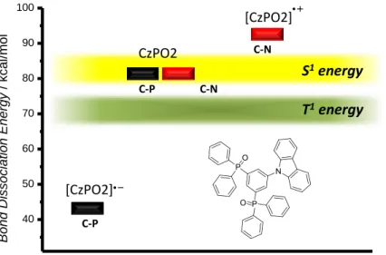
Almost all known hole transport materials are based on aromatic amines containing either triarylamine or carbazole moieties. For electron transport materials in contrast, a much wider structural diversity of materials is available. The employed materials range from phosphinoxides over a variety of nitrogen and oxygen containing heterocyles (oxadiazoles, triazines, pyridines, phenantrolines, benzimidazoles, etc.) and metal-organic compounds to fully aromatic hydrocarbons. As a matter of course, there is not “one general” pathway explaining the chemical degradation behavior of electron conducting materials. We will start this section with a “bridge material”, the ambipolar carbazole containing phosphine oxide CZPO2. This material exhibits both electron and hole conducting properties and follows, at least partly, the same exciton induced degradation pathway as the hole transporting materials. Quantum chemical calculations on CZPO2 by Chiu et al. revealed that the C-P bond dissociation energy is equal to that of C-N bonds, which enables the cleavage through the first singlet excited state (Figure 7).[28] This results in both, dissociation of the carbazole (discussed in the previous section) and the phosphinoxide unit from the benzene core. The main cause for a fast degradation compared to “pure” arylamines however, is the instability of the radical anion species formed through electron transport, resulting in the decrease of the C-P bond dissociation energy to almost half the original value. In contrast, the formation of the radical cation species of the carbazole unit leads to a stabilization of the C-N bond (about 10 kcal/mol). Therefore C-P bond containing materials might undergo bond cleavage not only, but also due to the presence of negative charge carriers.
Figure 7. Dissociation energies of the different bond types of the bipolar condcuting material CzPO2.
One important and well investigated class of fluorescent host and electron transporting materials are azaaromatic compounds, like quinolines (AlQ3, BAlQ2), phenanthrolines (BPhen) or benzimidazoles. Much effort has been spent so far on elucidating the degradation mechanisms of these materials, especially of AlQ3. Unipolar current devices of AlQ3 as well as devices with tunable hole injection efficiency clearly indicated that hole injection in this material leads to device degradation.[29-31] Investigations by Papadimitrakopoulos et al., showing the irreversible oxidation behavior of AlQ3 in cyclic voltammetry measurements,[32] are consistent with the thesis of the hole current induced formation of unstable cationic AlQ3•+ species.[33-34] Scholz et al. assumed after LDI-TOF-MS measurements that excited AlQ3 molecules undergo a reversible ligand-dissociation to AlQ2+ (Scheme 2).[35] While MS signals at 648 amu suggest the subsequent reaction of the cationic species with the adjacent hole blocking material BPhen (4,7-di(phenyl)-1,10- phenanthroline), no information could be obtained whether a charge transfer species [AlQ2+BPhen]+ or even a coordinatively bound complex [AlQ2BPhen]+ is generated.[36]
Initially assumed dimerization reactions of AlQ3 to the charged Al2O5+ species[35] turned out to occur exclusively at a very high density of excited molecules, like for example during the laser ionization process for mass spectrometric investigations and are therefore most likely no relevant degradation pathway in OLEDs.[36] The free chinoline ions, resulting from the dissociation process, can react to non-emissive, fluorescence quenching degradation products.[32, 35]
40 50 60 70 80 90 100
Bond Dissociation Energy / kcal/mol
C-N C-P
C-P
CzPO2 C-N
[CzPO2]
[CzPO2]
S
1energy
T
1energy
Scheme 2. Dissociation and degradation pathways of tris(8-hydroxy-quinolinato)aluminium AlQ3.
Later on the destructive role of hole accumulation at the layer-interface was qualified, realizing that high electron density in the AlQ3 layer causes similar irreversible luminescence efficiency loss in the device. It is assumed that electron traps of still unknown nature (chemical degradation is suggested) with a luminance efficiency of < 1% compared to AlQ3 are formed near the interface.[30, 37]
As quenching sites prevent emission from a large number of molecules surrounding them, it is obvious that even a relatively small amount of degraded AlQ3 molecules has a pronounced effect on the quantum efficiency of the whole device. Hence it is imperative to prevent accumulation of charges (both electrons and holes) in or at the interface of the AlQ3 layer. As it is known that the transit time of holes through the HTL is up to three orders of magnitude faster than for the electrons through AlQ3,[38-39] it is important to fine-tune the balance between electron and hole injection and mobility. Using hole transport materials with low ionization potentials is only one example, which can improve device stability. The resulting energy barrier between the HTL and the AlQ3 layer impedes the hole injection in the latter.[24, 33] This reduces hole induced AlQ3 degradation. A complementary route to enhance the device durability is to improve electron mobility. This was for example achieved by doping AlQ3 with materials like BAlQ2[40] or BPhen.[40-41]
Investigations of the hole blocking and electron transport material BPhen showed besides faster electron transit properties compared to AlQ3 some drawbacks concerning the chemical stability in stressed devices. Dimerization as well as trimerization of BPhen molecules (Scheme 3) could be observed, leading to charge traps in the form of charged and neutral oligomers at the EML/HBL interface.[19, 35] These products can generally be ascribed to nucleophilic reactions of the lone electron pair of the sp2-hybridized nitrogen
atom of an azaaromatic compound with an adjacent radical cationic species.[31] BPhen degradation seems to be dependent on the total charges passing through the device and occurs mainly at high voltages.[42] BCP generally shows a higher stability compared to BPhen, as dimer formation could only be observed to a lower extent and trimer formation not at all.[35] This can be explained by the steric hindrance of the methyl groups in the 2-positions of BCP, which leads to the conclusion that the introduction of bulkier substituents can improve the stability of phenanthroline materials by shielding the sp2-nitrogens and impeding interactions with reactive species in the vicinity. In phosphorescent OLED devices BPhen can also form adducts with emitter fragments (see emitter section).[43-44] Both degradation pathways can result in the formation of gap states for charge carriers and excitons, causing significant luminance loss. Interestingly, complexation reactions of BPhen with the cathode materials Ag or Cs[36, 42, 45] are desired as an emerging interlayer, formed at the ETL/cathode interface during the evaporation of the cathode material, acts as a doped injection layer, enhancing electron injection into the ETL.[45]
Scheme 3. Oligomerization reactions of the phenantroline based electron transporters.
With the electron transport material BAlQ2 instead of BPhen, device lifetimes can be improved significantly.[46] Compared to BPhen, BAlQ2 seems to exhibits better chemical stability as no coordination products with phosphorescent emitters could be identified so far. Initially, this molecule was also considered to be inert regarding self-dimerization.[35] But it turned out that it undergoes this degradation pathway as well:[42] the excited complex suffers dissociation of the phenylphenolate ligand (Scheme 4). The so formed [Al(Me-Q)2]+ species can either undergo a subsequent back-reaction or a coordination with another excited BAlQ2 to the dimer [BAlQ2+Al(Me-Q)2]+. De Moraes et al. found this degradation to be dependent on the current density and assumed it to be caused by bimolecular annihilation reactions (see 2nd section).[42] They also observed a direct correlation between dimer formation and device lifetime.
Scheme 4. Dissociation and dimerization reactions of the electron transport material BAlQ2.
Fully aromatic hydrocarbons were always considered being favorable inert host materials as they lack disadvantageous features like weak bonds (C-N, C-metal, N-metal, C-P) and highly reactive nucleophilic centers (lone pairs). Therefore homolytic bond dissociations and nucleophilic addition reactions are no critical issues for this class of host materials. But having a very closer look at devices incorporating hydrocarbons like ADN and rubrene, respectively, Kondakov et al. noticed a slow but steady and irreversible decrease of these molecules in chromatography based analysis of photoexcited devices.[47] Degradation mechanisms comparable to those of the arylamines can be ruled out as the weakest covalent bond in ADN has a dissociation energy of ~120 kcal/mol. The S1 state energy of about 70 kcal/mol is therefore too low for exciton induced bond dissociation. Electron paramagnetic resonance (EPR) measurements nonetheless confirmed the generation of free spins during photoexcitation, formally carbon centered radicals. Oligomeric degradation products could be detected in significant amounts by gel permeation chromatography (GPC). It is assumed that the formation of these high-molecular-weight products takes place due to excited state reactions of adjacent molecules resulting in dehydrogenation reactions. Mass spectrometric investigations and additional comparison of the chromatographic retention times and absorption spectra with an authentic sample revealed the major low-molecular-mass product to be cADN (Scheme 5). The photocyclic ringclosing reaction of ADN to cADN is quite surprising as this reaction type commonly generates 6-membered-ring-derivatives. In contrast, 5-membered ring closure requires high-energy intermediates, formally biradicals. Quantum chemical calculations confirmed in case of ADN a stable biradical intermediate ADN••, which can trap both electrons and holes. Various hydrogen transfer reactions of this biradical with ion radicals or neutral adjacent molecules can occur to form neutral and charged radical species.[48] These can act as deep traps, non-radiative recombination centers and quenchers. Due to its absorption properties and the negligible fluorescent quantum yield (< 1%), the cyclization product cADN acts as an efficient fluorescence quencher.


![Figure 9. Some examples of thermally stable materials in OLED applications: TDAB derived, [56-58]](https://thumb-eu.123doks.com/thumbv2/1library_info/4651119.1608293/43.892.127.784.102.514/figure-examples-thermally-stable-materials-oled-applications-derived.webp)