Data Flow Abstractions and Adaptations through Updatable Process Views
Jens Kolb,
Ulm University, Germany
jens.kolb@uni-ulm.de
Manfred Reichert
Ulm University, Germany
manfred.reichert@uni-ulm.de
ABSTRACT
The increasing adoption of process-aware information sys- tems (PAISs) has resulted in large process model collections.
To support users having different perspectives on these pro- cesses and related data, a PAIS should enable personalized views on process models. Existing PAISs, however, do not provide mechanisms for creating such process views or even changing them. Especially, changing process models is a fre- quent use case in PAISs due to evolving needs or unplanned situations. While process views have been used as abstrac- tions for visualizing process models, no work exists on how to change process models based on related views. This paper extends our approach for abstracting and changing process models based on updatable process views with a focus on the data perspective. In the context, of a view change we ensure up-to-dateness and consistency of all process views related to the same process model. To define process ab- stractions well-defined view creation operations can be ap- plied. Further, updates on process views (including the data perspective) are correctly propagated to the underlying pro- cess model. Then, all other views related to this process model are migrated to the new version of the process model.
Overall, our view framework enables domain experts to not only evolve the behavior of large processes based on appro- priate model abstractions, but also the data perspective.
1. INTRODUCTION
Process-aware information systems (PAISs) provide sup- port for business processes at the operational level. A PAIS strictly separates process logic from application code, relying on explicitprocess models [1]. This enables a separation of concerns, which is a well established principle in computer science to increase maintainability and to reduce costs of change [2]. The increasing adoption of PAISs has resulted in large process model collections. In turn, each process model may refer to different domains, organizational units, and user roles, and it may comprise dozens or even hundreds of activities [3]. Usually, different user groups need customized
Permission to make digital or hard copies of all or part of this work for personal or classroom use is granted without fee provided that copies are not made or distributed for profit or commercial advantage and that copies bear this notice and the full citation on the first page. To copy otherwise, to republish, to post on servers or to redistribute to lists, requires prior specific permission and/or a fee.
SAC’13March 18-22, 2013, Coimbra, Portugal.
Copyright 2013 ACM 978-1-4503-1656-9/13/03 ...$10.00.
views on the process models relevant for them, enabling a personalized process abstraction and visualization [4]. For example, business managers rather prefer an abstract pro- cess overview, whereas process participants need a detailed view of the process parts they are involved in. Hence, pro- viding personalized process views is a much needed PAIS feature. Several approaches for creating process model ab- stractions based on process views have been proposed [5, 6, 7]. However, these focus on view creation and visualization, but neither consider the data perspective of process models nor process model evolution [2, 1]. More precisely, most ex- isting techniques for creating process views do not allow for properly abstracting the data perspective of a process model (e.g., through creating business objects). Further, changing the data perspective of a large process model based on up- dates of corresponding model abstractions is also not sup- ported. Hence, changes must be directly applied to the core process model, which constitutes a complex as well as error- prone task for domain experts, particularly at the presence of large process models. To overcome this drawback, in addi- tion to creating process model abstractions, users should be allowed to change the controlanddata flow of large process models through updates of corresponding process views.
In theproView1project, we address these challenges by not only supporting the creation and visualization of process views, but by additionally providing change operations that enable users to modify a process model through updating any related process view [8]. In this context, all other views defined for the changed process model must be migrated to its new version as well. Note that this paper focuses on the abstraction and adaptation of the data perspective, while the approach we described in [8] deals with behavioural (i.e., control flow) changes. Besides view-based abstractions and changes, proView enables alternative process model repre- sentations (e.g., tree-based, form-based, and diagram-based) and provides different interaction techniques (e.g., gesture- vs. menu-based) [9, 10, 11]. Our overall goal is to enable domain experts to interact with (executable) process models they are involved in.
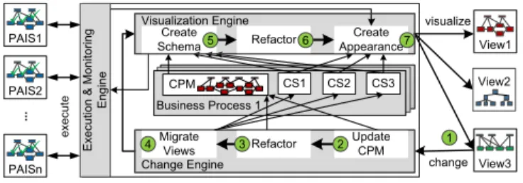
Fig. 1 gives an overview of theproViewframework: Abusi- ness process is captured and represented through aCentral Process Model (CPM). In addition, for a particular CPM, so-called creation sets (CS) are defined. Each creation set specifies the schema and appearance of a particular process view. Section 2 gives more details. For defining, visualizing, and updating process views, the proView framework pro- vides engines enablingvisualization,change, andexecution
1http://www.dbis.info/proView
Visualization Engine
Change Engine
CS2
CS1 CS3
Migrate Views
Create Appearance Create
Schema Refactor
Business Process 1
View2
4 1
5 6 7
Execution & Monitoring Engine
execute
visualize
change
...
Refactor
3 Update
2 CPM PAIS1
ü ü ü
PAIS2 ü ü ü
PAISn ü ü ü
View3 View1 CPM
Figure 1: The proView Framework
& monitoring. Thevisualization engine generates a process view based on a given CPM and the information maintained in creation set CS, i.e., the CPM schema is transformed to the view schema by applying the corresponding view cre- ation operations specified in CS (Step 5). Afterwards, the resulting view schema issimplified by applying well-defined refactoring operations(Step 6). Finally, Step 7customizes the visual appearance of the view, e.g., by creating a tree-, form-, or activity-based visualization [6, 9]. Section 3 pro- vides insights into these steps.
When a user updates a view schema, the change engine is triggered (Step 1). First, the view-based model change is propagated to the underlying CPM using well-defined change propagation algorithms (Step 2). Next, the schema of the modified CPM is simplified (Step 3), i.e., behaviour- preserving refactorings are applied to foster model compre- hensibility, e.g., by removing surrounding gateways not needed anymore. Afterwards, the creation sets of all other views associated with the CPM are migrated to the new CPM schema version (Step 4). This becomes necessary since a creation set may be contradicting with the changed CPM schema. Finally, all views are recreated (Steps 5- 7) and presented to users. Section 4 presents view update opera- tions and migration rules required to change business pro- cesses based on process view updates. Section 5 sketches the validation ofproView. Section 6 discusses related work and Section 7 summarizes the paper.
2. BACKGROUND
A process model is represented by aprocess schemacon- sisting ofprocess nodesas well as thecontrol anddata flow between them (cf. Fig. 2). For control flow modeling,gate- waysandcontrol flow edgesare used (cf. Definition 1). Data flow is expressed through data elements and corresponding read/write data edges.
A
B
C F G
D E StartFlow Activity
ANDsplit
ET_SoftSync
EndFlow LOOPsplit
LOOPjoin
XORsplit XORjoin
ANDjoin SESE block (Single Entry Single Exit) d1
C
DataElement ReadAccess
WriteAccess
Figure 2: Example of a Process Model
Definition 1. Aprocess model is defined as a tuple P = (N, D, E, EC, N T, ET) where:
• N is a set of nodes (i.e., activities and gateways),
• D is a set of data elements,
• E=CE∪˙DEis a set of edges that comprises control flow edgesCE ⊂N×N and data flow edgesDE ⊂ (N×D)∪(D×N),
• EC:E →Conds∪ {True}assigns transition condi- tions to control edges,
• N T:N→ {StartF low, EndF low, Activity, AN Dsplit, AN Djoin, XORsplit, XORjoin, LOOP split, LOOP− join}assigns node type N T(n) to each noden∈ N;
N is divided into disjoint sets of activity nodes A (N T =Activity) and gateways S (N T 6=Activity), i.e.,N=A∪˙ S,
• ET :E→ {ET Control, ET Sof tSync, ET Loop, ET DataF low} assigns an edge typeET(e) to each edgee∈E,
• DET : E → {always, optional, never}describes the type of data access for each data edge.
Definition 1 can be used for representing the schemes of both the Central Process Model (CPM) and associated process views. In particular, it can be applied to activity- centered modeling languages, even though not restricted to a particular one. This paper uses BPMN as notation due to its widespread use. Further, to each data edge e func- tionDET(e) assigns a value indicating whether the corre- sponding data element is always, optionally or never ac- cessed. Thereby, always indicates that the data element is mandatory for the corresponding activity. In turn, op- tional expresses that it is not mandatory to perform the activity. If no correspondence exists, DET returns never.
We further assume that a process schema iswell-structured, i.e., sequences, branchings (of different semantics), and loops are specified as blocks with well-defined start and end nodes having same gateway type. These blocks—also known as SESE blocks (cf. Definition 2)—may be arbitrarily nested, but must not overlap (like blocks in WS-BPEL). To increase expressiveness, sync edges allow for across-block synchro- nization of parallel activities (similar to BPEL links). In Fig. 2, for example, activityE must not be enabled before completingG.
Definition 2. Let P = (N, D, E, EC, N T, ET) be a pro- cess model andX ⊆N be a subset of activity nodes (i.e., N T(n) =Activity, ∀n∈X). Then: SubgraphP0 induced by X is called SESE (Single Entry Single Exit) block iff P0 is connected and has exactly one incoming and one out- going edge connecting it with P. Further, let (ns, ne) ≡ M inimalSESE(P, X) denote the start and end node of the minimum SESE comprising all activities fromX⊆N. How to determine SESE blocks is described in [12]. Since we presume a well-structured process schema, a minimum SESE can be always determined.
3. VIEW CREATION OPERATIONS
To create a process view on a given process model, proper abstraction techniques applied to this model are required.
For this purpose,proViewprovideselementary view creation operations. In turn, these elementary operations may be combined to realizehigh-level operations (e.g., show all my activities and their precedence relation). In particular, such high-level operations enable users to create process views at
a high level of abstraction [13].
At the elementary level, two categories of operations are distinguished: reduction and aggregation. An elementary reduction operation hides any process element (e.g., data element or activity) of the original process model in the cre- ated process view. In turn, an elementaryaggregationoper- ations abstracts a set of process nodes to one node, e.g., by combining a set of data elements/activities into one abstract business object/activity.
Generally, a process view can be created through the con- secutive application of elementary operations to a process model. Remember that the latter represents a business pro- cess and is denoted asCentral Process Model (CPM). Gen- erally, any CPM may have several associated process views.
Definition 3. Let CPM be a process model. A process view V(CPM) is described through a creation set CSV = (CP M, Op, P S) with:
• CP M = (N, D, E, EC, N T, ET) is the process model for which the view is defined; CPM is denoted asCen- tral Process Model,
• Op = hOp1, . . . , Opni is the sequence of elementary view creation operations applied to CPM:Opi∈ {RedActivity, RedDataElement, AggrSESE, . . .},
• P S = (P S1, . . . , P Sm) defines the settings (i.e., val- ues) of a number of configuration parameters for the view creation operations applied.
Definition 3 expresses that a process view can be created through the consecutive application of the operations spec- ified in the corresponding creation set. In this context, con- figuration parameters (shortly: parameter) are required to describe how high-level operations shall be mapped to ele- mentary view creation operations, depending on the selected nodes in the CPM (see [13] for details). Section 4 shows that these parameters are required to enable automatic change propagation from a view to its underlying CPM.
A node n in aprocess view V either directly corresponds to noden of the CPM or it abstracts a set of CPM nodes.
CP M N ode(V, n) reflects this by returning either nodenor a node setNnofCP M = (N, D, E, EC, N T, ET), depend- ing on the creation setCSV = (CP M, Op, P S)with Op= hOp1, . . . , Opki.
CP M N ode(V, n) =
(n n∈N∪D Nn ∃Opi∈Op:Nn
Opi
−→n
3.1 Creating Process Views Based on Schema Reduction
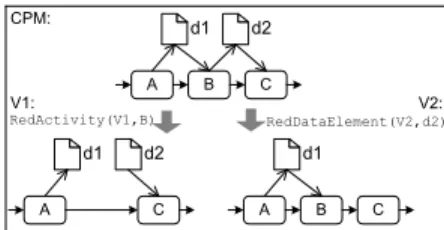
Any view creation component should allow removing ac- tivities or data elements within a process view. This is required to hide irrelevant or confidential process details from a particular user group; e.g., hiding technical data ele- ments (e.g., database connection data) or privacy-/security- sensitive data elements (e.g., user names). For this purpose, proView provides elementary reduction operations RedAc- tivity(V,n)andRedDataElement(V,d)(cf. Fig. 3).
View creation operationRedActivity(V,n) removes node n together with its incoming and outgoing control flow edges.
It further inserts a new control flow edge linking the prede- cessor ofnwith its successor in viewV (see view V1 in Fig.
A B C D E
F
{LATE_EARLY}
X
{LATE_LATE} X
EARLY_* LATE_* *_EARLY *_LATE
{EARLY_LATE,EARLY_EARLY} X
X a) RedActivity(V,B)
V1: V2:
CPM:
A B CDE
A C D
OpV2={
RedActivity(F), AggrSESE(C,D,E}
Change in View V1 InsertParallel ({C,D},X,V1) 1
a) Initial Situation
2 Determining Insert Position in CPM (depends on Parameter InsertBlockMode) 3 Migrating Views
Results b)+c) InsertBlockMode=
LATE_EARLY
A B CDEX
X
A B C D E
b) Updated View V2
AggrPartlyMode=AGGR AggrPartlyMode=SHOW
c) Updated View V2
A B C
A C
b) AggrSESE(V,{B,C})
A B C D
A BC D
A
B C
D
c) AggrComplBranches(V,{A,B,C}) ABC
D
RedActivity(V1,B)
A B C
d1 d2
A C
d1 d2
A B C
d1
RedDataElement(V2,d2)
Figure 3: Process View Creation: Reduction
Algorithm 1: RedDataElement(V,d) D0 =D\ {d}
E0=E
f orall(e= (es, ee)in E) if((es==d)||(ee==d))
E0=E0\ {e}
Table 1: View Create Operation: RedDataElement
3). Furthermore, it removes all data edges associated with noden. In certain cases, applying this operation results in a process view with “incorrect” data flow. For example, in Fig. 3, data elementd2 is never written from the perspec- tive of viewV1. Of course, the data flow of a CPM is not modified when applying this operation during view creation.
View creation operationRedDataElement(V,d)removes data element d in process view V as well as all associated data flow edges (cf. Table 1). As opposed to operationRedActiv- ity, data flow correctness of the CPM is preserved since all writing and reading data flow edges are removed together with the data element itself (cf. view V2 in Fig. 3). Obvi- ously, the semantics of the data flow then changes compared to the one in the corresponding CPM.
When reducing process elements in a process view unused control flow structures may remain (e.g., empty branches).
Therefore, refactoring operations are applied to simplify the resulting control flow structure and thus to increase view comprehensibility [8, 3].
3.2 Creating Process Views Based on Schema Aggregation
Anaggregationoperation takes a set of process nodes as input and combines them into an abstracted node in the process view. For example, operation AggrSESE(V, N0) removes all activities of the SESE block induced by node set N0 and inserts an abstract activity in the resulting process view instead (see view V1 in Fig. 4). Associated data ele- ments are aggregated as well, iff all incoming/outgoing data edges are connected to activities of N0. Other associated data elements are kept in the view and their data edges are reconnected to the newly aggregated activity (see view V1 in Fig. 4).
AggrComplBranches(V, N0) is an elementary operation aggregating complete branches of an XOR/AND block to a single branch with one abstracted node. N0 must comprise the activities of the branches (i.e., between split and cor- responding join gateway) that shall be replaced by a single branch with one aggregated node. In this case, data ele- ments are handled similar to AggrSESE.
OperationAggrDataElements(V, Da) aggregates a set of
Algorithm 2: AggrSESE(V,Na) N0 =N\Na∪ {nnew}
E0=updateControlF lowEdges(E, Na) Da=getAssociatedDataElements(CP M, Na) f orall(d in Da)
if(isReadAccess(d, Na)) enew= (d, nnew) E0=E0∪ {enew}
if(accessedByAllT races(d, Na)) DET(enew) :=always else
DET(enew) :=optional elseif(isW riteAccess(d, Na))
//analogous f or write access E0=removeDataEdges(E0, d, Na)
Table 2: View Create Operation: AggrSESE
AggrSESE(V1,{B,C})
A B C
d1 d2
d1
V1: V2:
CPM:
A B C
d1d2 AggrDataElements
(V2,{d1,d2})
A BC
Figure 4: Process View Creation: Aggregation
data elements to one abstract data element (see view V2 in Fig. 4). For example, a set of data elements related to a patient treatment process may be combined to one abstract patient data element. Hence, operationAggrDataElements removes all data elements of setDaand inserts an abstract data element in process viewV. Additionally, corresponding data edges are updated by replacing old ones connecting el- ements ofDawith activities connecting the abstracted data element with corresponding activities (cf. Table 3). The newly added data edge type must be the same as in the CPM. E.g., aggregating anoptional as well asalways writ- ten data element results in analways written abstract one.
4. VIEW UPDATE OPERATIONS
Process views are not only required for enabling person- alized process visualization through abstracting the under- lying CPM. They shall also provide the basis for changing large process models based on respective abstractions. Sec- tion 4.1 describes how such updates of a process view can be
Algorithm 3: AggrDataElement(V,Da) D0=D\Da∪ {dnew}
E0=E
f orall(e= (es, ee)in E) if(es∈Da)
enew= (es, dnew)
if(DET((es, dnew)) ==never) DET((es, dnew)) :=DET(es, ee) elseif((DET((es, dnew)) ==always)
||(DET(es, ee) ==always)) DET((es, dnew)) :=always elseif(ee∈Da)
//analogous f or read access E0=E0∪ {enew, ee} \ {e}
Table 3: View Create Operation: AggrDataElement
accomplished and then propagated to the underlying CPM.
Section 4.2 then presents migration rules for updating all other process views also associated with the changed CPM.
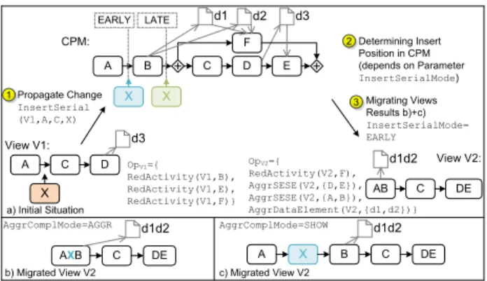
Note that this paper focuses on operations directly modi- fying the data flow. In turn, an example of control flow updates is depicted in Figure 5. View update operations re- lating to the control flow perspective are outside the scope of this paper and are described in [8].
A B C D E
F
X X
EARLY LATE
X
OpV1={
RedActivity(V1,B), RedActivity(V1,E), RedActivity(V1,F)}
View V1:
View V2:
CPM:
AB C DE
A C D OpV2={
RedActivity(V2,F), AggrSESE(V2,{D,E}), AggrSESE(V2,{A,B}), AggrDataElement(V2,{d1,d2})}
Propagate Change InsertSerial (V1,A,C,X) 1
a) Initial Situation
2 Determining Insert Position in CPM (depends on Parameter InsertSerialMode) 3 Migrating Views
Results b)+c) InsertSerialMode=
EARLY
AXB C DE
b) Migrated View V2
AggrComplMode=AGGR AggrComplMode=SHOW
c) Migrated View V2
d2 d3
d1
d3
d1d2
C DE
A X B
d1d2 d1d2
Figure 5: Example of a Process View
4.1 View Update Operations
When allowing users to change a business process model based on a personalized process view, it must be ensured that this change can be automatically propagated to the underlying CPM without causing syntactical or semantical errors. Hence, well-defined view update operations are re- quired that guarantee for a proper propagation of the respec- tive view changes to the CPM. Table 4 gives an overview of view update operations related to data flow.
Propagating view changes to the corresponding CPM is not straightforward. In certain cases, there might be am- biguities regarding the propagation of the view change to the underlying CPM. For example, it might not be possi- ble to determine a unique position for inserting an activity or data edge in the CPM due to the abstractions applied when creating the view. Consider the example from Fig.
6. Inserting the read data edge (d1,BC)in viewV1 allows for several insert positions in the related CPM. More pre- cisely, there are ambiguities in how to transform the view change into a corresponding CPM change, i.e., data element
InsertDataElement(V,d)
Inserts data elementdin viewV without any data edges.
InsertDataEdge(V,de,det)
Inserts a new data edgedeand corresponding data edge type det in view V. The corresponding parameter InsertEdge- Mode={EARLY,LATE,ALL} describes the propagation be- haviour in case of ambiguities.
ChangeDEType(V,de,det)
Changes the data edge type of data edgedeto the new data edge typedetin process viewV.
DeleteDataElement(V,d)
Deletes data elementdin process viewV as well as all associ- ated data edges.
DeleteDataEdge(V,de)
Deletes data edgedein process viewV.
Table 4: Update Operations for Process Views
Algorithm 4: InsertDataEdge(V,de,det) if(de= (d, n)∧n∈N) //reading edge
N0=CP M N ode(V, n) switch(InsertEdgeM ode) : EARLY :
DEnew={(d, f irst(N0))}
DET((d, f irst(N0))) :=det LAT E:
DEnew={(d, last(N0))}
DET((d, last(N0))) :=det ALL:
f orall(n0 in N0)
DEnew=DEnew∪ {(d, n0)}
DET((d, n0)) :=det D0=D∪DEnew //analogous for writing edge
Table 5: View Create Operation: AggrDataElement
d1 may be read by activityB or activityC. Note that this ambiguity results from the aggregation of B and C in the context of the view creation. However, when propagating view updates to a CPM, users must not be burdened with resolving such ambiguities. Instead automated propagation of view updates to a CPM shall be based on parameteriz- able propagation policies. Hereafter, we introduce parame- terizable view update operations that may be configured to automatically propagate view updates to a CPM resolving ambiguities if required (cf. Table 1). We exemplarily pro- vide an algorithm for operationInsertDataEdgeto indicate how a view change can be transformed into a corresponding CPM change, taking such parameterizations into account.
A B C
d1
d1 V1:
CPM‘:
A BC
CPM‘‘:
InsertDataEdge (V1,(d1,BC),always)
A B C
d1 AggrSESE (V1,{B,C}) InsertEdgeMode=
EARLY
InsertEdgeMode=
LATE
? ?
Figure 6: Ambiguity when Propagating View Changes to the CPM
As shown in Figure 6,InsertDataEdge(V,de,det)adds data edgedeto process view V. Data edgede= (n1, n2) indicates whether a read/write data edge is considered, whereasdet denotes the used data edge type (e.g., optional, always).
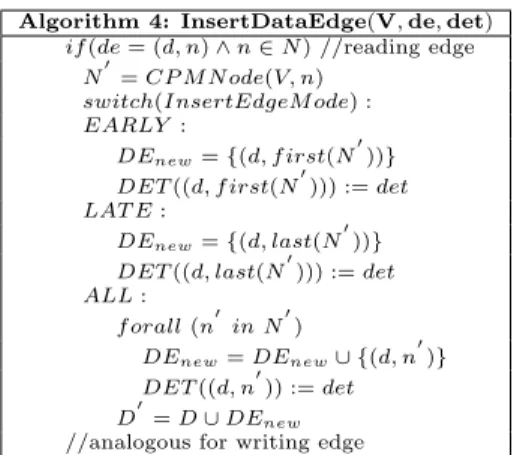
Algorithm 4 (cf. Table 5) shows how a view change, as de- scribed by operation InsertDataEdge, can be transformed into a schema change of the related CPM. First of all, it must be determined whether the data edge is a write or read edge. In case of a read edge, the activityn, which reads the related data element in view V, is identified. Then, function CPMNode (cf. Section 2) is applied to obtain the nodes corresponding tonin CPM. Depending on the value ofIn- sertEdgeMode, the data edge is added to the CPM at the earliest/latestposition taking returned node setN0 of func- tion CPMNode into account. IfInsertEdgeMode=ALL, data edges are added to all nodes of node setN0.
Obviously, inserting a data edge might violate the cor- rectness of the data flow of the CPM. For example, when
inserting a read data edge at a point from which the data element will not have been written yet. Table 6 provides an overview of the properties of each update operation (cf. Ta- ble 4). Property dependency generating describes whether the application of a particular operation, generates new data flow dependencies (e.g., through edges). In such cases, cor- rectness of the data flow of the underlying CPM must be checked. Propertydependency preserving expresses that all existing data flow dependencies are preserved when applying a view update operation. Next, propertydata flow correct- ness preserving describes, which operations preserve data flow correctness and which might violate it. All data-related update operations preserve control flow correctness.
Operation dependency generating dependency preserving dataflow correctness preserving controlflow structure preserving
InsertDataElement - + + +
InsertDataEdge + + - +
ChangeDEType - - - +
DeleteDataElement - - + +
DeleteDataEdge - - - +
Table 6: Overview of Operation Properties
4.2 Migrating Process Views to a New CPM Version
When changing a CPM through updating one of its as- sociated views, all other views defined on this CPM must be updated as well. More precisely, it must be guaranteed that all process views are up-to-date and hence users always interact with the current version of a process model and re- lated views respectively. To ensure this, after propagating a view change to a CPM, the creation sets of all other pro- cess views must be migrated to the new CPM version (cf.
Definition 3). Note that in certain cases this creation set will contradict to the CPM (cf. Table 7). Especially when deleting a data element, which is reduced (i.e., M1) or ag- gregated (i.e., M2) in a process view, migration rules must be applied to migrate creation sets.
Applying a change to the CPM and recreating the process views afterwards allows us to guarantee that all views are up- to-date. Since the recreation of a process view is expensive, we developed a number of optimization techniques. First, instead of recreating all process views, this is only accom- plished for those views affected by the change. Second, when changing the creation set, the visualization engine exactly knows which parts of the process view changed; respective parts are then recreated.
Migration Rule M1(after applying DeleteDataElement(V,d):
∃RedDataElement(V, d) =Op1, Op1∈Op
⇒Op0=Op\Op1
Migration Rule M2(after applying DeleteDataElement(V,d):
∃AggrDataElement(V, Da) =Op1, Op1∈Op and d∈Da
⇒Op0=Op\Op1
Table 7: Process View Migration Rules
5. EVALUATION
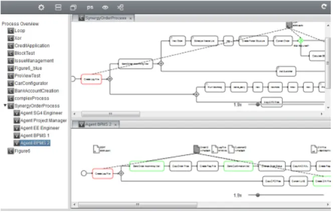
TheproView framework presented in this paper has been implemented as a proof-of-concept prototype in a client- server application. Further, it enables users to simultane- ously edit process models based on updatable process views [14]. Overall, theproView prototype demonstrates the ap- plicability of our framework (cf. Figure 7).
Figure 7: Proof-of-Concept Prototype
We further applied this prototype in an industry project, i.e., to theorder processing process of a mid-sized company in Germany. This process consists of 56 activities and in- volves six different user roles. In the top right, Figure 7 shows this process and on the bottom right an automati- cally generated view of an involved engineer is displayed.
This view is generated through high-level operation “show all my activities”. Overall, this study has provided promis- ing results. In particular, it is easier for process participants to understand process aspects relevant for them.
6. RELATED WORK
In the context of cross-organizational processes, views have been applied for creating abstractions of partner processes hiding private process parts [7, 15, 16, 17]. However, process views are manually specified by the process designer, but do not serve as abstractions for changing large process models as in theproView project.
An approach providing predefined process view types (i.e., human tasks, collaboration views) is presented in [5]. As opposed toproView, it is limited to these pre-specified pro- cess view types. In particular, the views are not used as abstractions enabling process change. In turn, [18] applies graph reduction techniques to verify structural properties of process schemas. TheproView project accomplishes this by enabling aggregations that use high-level operations. In [19], SPQR-tree decomposition is applied when abstracting process models. Opposed toproView, this approach neither takes other process perspectives (e.g., data flow) nor process changes into account.
The approach presented in [20] determines the semantic sim- ilarity between activities by analyzing the schema of a pro- cess model. The similarity discovered is used to abstract the process model. However, this approach neither distinguishes between user perspectives on a process model nor does it provide concepts for manually creating process views.
An approach for creating aggregated process views is de-
scribed in [21]. It proposes a two-phase procedure for ag- gregating parts of a process model not to be exposed to the public. Again, process view updates to evolve or adapt pro- cesses are not considered.
View models serving monitoring purpose are presented in [22, 23]. The focus is on the run-time mapping between process instances and views. Furthermore, views must be pre-specified manually by the designer.
[24] aligns technical workflows with business processes. It allows detecting changes through behavioural profiles and propagating them to change regions of the corresponding technical model. These regions indicate the schema region to which the change belongs. Automatic propagation is not supported. Similarly, [25, 26] describes a mapping model between a technical workflow and a business process. An automatic propagation of changes is not supported.
For defining and changing process models, various approaches exist. [27] presents an overview of frequently used pat- terns for changing process models; semantics of these pat- terns is described in [28]. Further, [1] gives a comprehensive overview on approaches enabling PAIS flexibility. In partic- ular, [29] presents an approach for adapting well-structured process models without affecting their correctness proper- ties. Based on this, [30] discusses concepts for optimizing process models over time and migrating running processes to new model versions properly. None of these approaches takes usability issues into account, i.e., no support for user- centered changes of business processes is provided.
The proView framework provides a holistic framework for personalized view creation. Further, it enables users to change business processes based on their views and guaran- tees that other views of the process model are adapted ac- cordingly. None of the existing approaches covers all these aspects and is based on rigid constraints not taking practical requirements into account.
7. SUMMARY AND OUTLOOK
We introduced theproViewframework and its formal foun- dation; proView supports the creation of personalized pro- cess views and the view-based change of business processes, i.e., process abstractions not only serve visualization pur- pose, but also lift process changes up to a higher seman- tical level. A set of update operations enables users to update their view and to propagate the respective schema change to the underlying process model representing the holistic view on the business process. Parameterization of these operations allows for automatically resolving ambigu- ities when propagating view changes; i.e., change propaga- tion behaviour can be customized for each view. Finally, we provide migration rules to update all other process views associated with a changed process model. Similar to the propagation, per view it can be decided how much informa- tion about the change shall be displayed to the user.
User experiments based on the proof-of-concept demon- strator are planned to test the hypothesis that view-based process changes improve the handling and evolution of large process models. Overall, we believe that view-based pro- cess model updates offer promising perspectives to better involve process participants and domain experts in evolving their business processes.
8. REFERENCES
[1] Reichert, M., Weber, B.: Enabling Flexibility in Process-aware Information Systems - Challenges, Methods, Technologies. Springer (2012)
[2] Weber, B., Sadiq, S., Reichert, M.: Beyond Rigidity - Dynamic Process Lifecycle Support: A Survey on Dynamic Changes in Process-Aware Information Systems. Computer Science - Research and Development23(2009) 47–65
[3] Weber, B., Reichert, M., Mendling, J., Reijers, H.A.:
Refactoring Large Process Model Repositories.
Computers in Industry62(2011) 467–486 [4] Streit, A., Pham, B., Brown, R.: Visualization
Support for Managing Large Business Process Specifications. In: Proc 3rd Int’l Conf Business Process Management (BPM’05). (2005) 205–219 [5] Tran, H.: View-Based and Model-Driven Approach for
Process-Driven, Service-Oriented Architectures. TU Wien, PhD Thesis (2009)
[6] Bobrik, R., Bauer, T., Reichert, M.: Proviado - Personalized and Configurable Visualizations of Business Processes. In: Proc. 7th Int’l Conf.
Electronic Commerce & Web Technology (EC-WEB’06), Krakow, Poland (2006) 61–71 [7] Chiu, D.K., Cheung, S., Till, S., Karlapalem, K., Li,
Q., Kafeza, E.: Workflow View Driven
Cross-Organizational Interoperability in a Web Service Environment. Information Technology and
Management5(2004) 221–250
[8] Kolb, J., Kammerer, K., Reichert, M.: Updatable Process Views for User-centered Adaption of Large Process Models. In: Proc 10th Conf Service Oriented Computing (ICSOC’12), Shanghai, China (2012) [9] Kolb, J., Reichert, M.: Using Concurrent Task Trees
for Stakeholder-centered Modeling and Visualization of Business Processes. In: Proc. S-BPM ONE 2012, CCIS 284. (2012) 237–251
[10] Kolb, J., Rudner, B., Reichert, M.: Towards Gesture-based Process Modeling on Multi-Touch Devices. In: Proc. 1st Int’l Workshop on
Human-Centric Process-Aware Information Systems (HC-PAIS’12), Gdansk, Poland (2012) 280–293 [11] Kolb, J., H¨ubner, P., Reichert, M.: Automatically
Generating and Updating User Interface Components in Process-Aware Information Systems. In: Proc. 10th Int’l Conf. on Cooperative Information Systems (CoopIS 2012). (2012) 444–454
[12] Johnson, R., Pearson, D., Pingali, K.: Finding Regions Fast: Single Entry Single Exit and Control Regions in Linear Time. In: Proc. Conf. on
Programming Language Design and Implementation (ACM SIGPLAN’94). (1993)
[13] Reichert, M., Kolb, J., Bobrik, R., Bauer, T.:
Enabling Personalized Visualization of Large Business Processes through Parameterizable Views. In: Proc.
26th Symposium On Applied Computing (SAC’12), Riva del Garda (Trento), Italy (2012)
[14] Kolb, J., Kammerer, K., Reichert, M.: Updatable Process Views for Adapting Large Process Models:
The proView Demonstrator. In: Proc. of the Business Process Management 2012 Demonstration Track, Tallinn, Estonia (2012)
[15] Chebbi, I., Dustdar, S., Tata, S.: The View-based Approach to Dynamic Inter-Organizational Workflow Cooperation. Data & Know. Eng.56(2006) 139–173 [16] Kafeza, E., Chiu, D.K.W., Kafeza, I.: View-Based
Contracts in an E-Service Cross-Organizational Workflow Environment. In: Techn. E-Services. (2001) 74–88
[17] Schulz, K.A., Orlowska, M.E.: Facilitating Cross-Organisational Workflows with a Workflow View Approach. Data & Knowledge Engineering51 (2004) 109–147
[18] Sadiq, W., Orlowska, M.E.: Analyzing Process Models Using Graph Reduction Techniques. Information systems25(2000) 117–134
[19] Polyvyanyy, A., Smirnov, S., Weske, M.: The
Triconnected Abstraction of Process Models. In: Proc.
7th Int’l Conf. on Business Process Management.
(2009)
[20] Smirnov, S., Reijers, H.A., Weske, M.: A Semantic Approach for Business Process Model Abstraction. In:
Advanced Information Systems Engineering, Springer Berlin (2011) 497–511
[21] Eshuis, R., Grefen, P.: Constructing Customized Process Views. Data & Knowledge Engineering64 (2008)
[22] Shan, Z., Yang, Y., Li, Q., Luo, Y., Peng, Z.: A Light-Weighted Approach to Workflow View. APWeb 2006 (2006) 1059–1070
[23] Schumm, D., Latuske, G., Leymann, F., Mietzner, R., Scheibler, T.: State Propagation for Business Process Monitoring on Different Levels of Abstraction. In:
Proc. 19th ECIS. Number Ecis, Helsinki, Finland (2011)
[24] Weidlich, M., Weske, M., Mendling, J.: Change Propagation in Process Models using Behavioural Profiles. Proc. 6th IEEE Int’l Conf. Services Comp.
(2009) 33–40
[25] Buchwald, S., Bauer, T., Reichert, M.: Bridging the Gap Between Business Process Models and Service Composition Specifications. In: Service Life Cycle Tools and Technologies: Methods, Trends and Advances. IGI Global (2011) 124–153
[26] Branco, M.C., Troya, J., Czarnecki, K., K¨uster, J., V¨olzer, H.: Matching Business Process Workflows Across Abstraction Levels. In: Proc. MODELS 2012, Innsbruck, Italy (2012)
[27] Weber, B., Reichert, M., Rinderle-Ma, S.: Change Patterns and Change Support Features - Enhancing Flexibility in Process-Aware Information Systems.
Data & Knowledge Engineering 66(2008) 438–466 [28] Rinderle-Ma, S., Reichert, M., Weber, B.: On the
Formal Semantics of Change Patterns in Process- aware Information Systems. In: Proc 27th Conf on Conceptual Modeling (ER’08), Springer (2008) 279–293
[29] Reichert, M., Dadam, P.: ADEPTflex - Supporting Dynamic Changes of Workflows Without Losing Control. J of Intelligent Inf. Sys.10(1998) 93–129 [30] Rinderle, S., Reichert, M., Dadam, P.: Flexible
Support of Team Processes by Adaptive Workflow Systems. Distributed and Par. Databases16(2004) 91–116