Quantum transport simulations:
sensing DNA
Hauptseminar SS2016
Frank Schulz
Tutor : Ganesh Sivaraman
1 Introduction
Quantum transport simulations are a very important concept for simulating electronic devices on the nanometre and sub-nanometre scale.[1] In this handout, and the related
’Hauptseminar’ talk, we will discuss the concept of one of these kinds of simulation types - namely the non-equilibrium Greens Function formalism (or short NEGF formalism) - and how they can be used in order to simulate DNA sequencing devices [2]. In this context, we will mainly focus on the usage of graphene nano-ribbons (or short GNRs) with either a nano-pore embedded in them[3], or a graphene nano-gap in between two GNRs [4].
1.1 Motivation
But why do we even bother looking into these new sequencing techniques? As you may know, the first attempt to sequencing the human genome was started in 1990 by the US government under the name of the ’Human Genome Project’.[5] This project was successfully complete in the year 2003, but all in all it cost about $2.7 billion ($2,700,000,000) [6]. At that time, the so-calledSanger method[7] was used in order to sequence the DNA. This method is reliant on a whole lot of different reagents - which are of course very costly - and they also require quite a lot of time in order to analyse them. In order to achieve a better understanding of genetics, mutations, and epigenetics, it is vital to have a low-cost, highly parallelizable way of sequencing DNA. This could lead to so- calledpersonalized medicine, meaning that it would be affordable for an average person to have their genome sequenced in order to find potential weaknesses or predispositions for certain illnesses. The goal we would have to reach in order to make this possible, is estimated to be about only $100 per genome. In order to achieve this kind of cost, we need some more sophisticated ways of sequencing DNA, going away from the chain- terminating methods of Sanger.
2 What is DNA?
We need a basic understanding of how DNA (short for deoxyribonucleic acid) is built up and how the physical properties of the DNA can allow us to sequence it on a single-base resolution.[8]
2.1 Coarse structure
DNA is a biomolecule consisting of a sugar-phosphate backbone, to which the four dif- ferent nucleobases are attached, as we can see in figure 1. The genetic information is encoded in the sequence of the nucleobases, namely Guanine (G), Adenine (A), Cytosine (C) and Thymine (T). In RNA, Thymine is usually replaced by Uracil (U). To each nu- cleobase, there’s a complementary counterpart which will form hydrogen bonds in order to form something like a double-stranded DNA, as shown in figure 1. The conformation
Figure 1: Chemical structure of a double-stranded DNA, with the sugar-phosphate back- bone additionally marked with a solid ribbon[9].
of the DNA molecule plays an important role during sequencing, since we need a single stranded DNA for the usage of a nano-pore.
The chemical structure, together with the direction of their dipole moment, is shown in figure 2. Just by looking at the chemical structure, we can already tell some differences
Figure 2: Chemical structure of the four nucleobases Adenine, Guanine, Thymine and Cytosine with the direction of their respective dipole [8].
between the four bases. The most prominent one would probably be the size of Adenine and Guanine compared to that of Thymine and Cytosine. While Thymine and Cytosine only consist of one ring - they are called pyrimidines - Adenine and Guanine consist of two rings - these are called purines - which makes them significantly bigger. Also, the dipole moment of the four bases seem to differ as well, which already indicates that we might have a shot at trying to identify them over their electronic structure.
3 The Non-Equilibrium Greens Function Formalism
As we could see, in order to distinguish between the different types of nucleobases on a single-base resolution, we will definitely need some kind of quantum-mechanical de- scription of the system and use the physical properties in order to identify the different nucleobases on a quantum-mechanical level. In order to simulate these kinds of quantum mechanical systems, we could of course try and solve the Schr¨odinger equation in order
to get a accurate description of our system, but as we know, this approach is not really sensible for the needed time- and length-scales, and also the number of electrons. So instead, we need another approach, especially regarding the electronic transport of the system. We know that instead of solving the Schr¨odinger equation, we can use thedensity functional theory (DFT) [10] in order to describe our system. But in order to describe this quantum transport phenomena, we need an extension to this method, and that’s where the so-callednon-equilibrium Greens Function (NEGF) formalism can be used [2].
The NEGF formalism provides a sound concept for calculating electronic transport on a quantum-mechanical level. This will allow us to calculate the quantities of interest - such as current, and conductivity - for our DNA sequencing device. Figure 3 illustrates the procedure of the NEGF formalism. The system we are looking at consists of a central
Figure 3:A The system consisting of the central device connected to two semi-infinite leads and B the procedure scheme to analyse the system [2]
device, in whose electronic properties we are interested when it is coupled to some con- tacts. Later on we will see how this can be applied to our nano-pores, where the device describes the pore with the included DNA strand, and the two contacts represent the electrodes that are attached to the nano-pore. When describing these kinds of systems within the NEGF formalism, we can assign so-calledself-energies to the contacts, which contain all the information about the coupling to the central device and how they change the energy of it. Together with the Hamiltonian of the central device - which we can obtain from DFT - we can then perform the self-consistent loop in figure 3Bin order to calculate the electron density matrixρ of the system, which contains information about the electronic structure of the system. And with this, we can calculate all the quantities of interest, such as current, conductivity and transmission.
In order to demonstrate the NEGF, we will use the example of the one-particle equa-
tions in order to show how the formalism works. [11] For that matter, we start with the Schr¨odinger equation
H|ψi=E|ψi (1)
where we can then divide the Hamiltonian and wavefunction of the system into contact (index 1,2) and device (index d)
H1 τ1 0 τ1† Hd τ2†
0 τ2 H2
|ψ1i
|ψdi
|ψ2i
=E
|ψ1i
|ψdi
|ψ2i
(2)
where τ1,2 describe the interaction of the device and the contacts. We can now define the Greens Function as a solution to the Schr¨odinger equation
[E−H]G= 1 or G= [E−H]−1. (3)
Since we are interested in the properties of the central device, we will calculate the Greens Function of the device separately via
Gd= [E−Hd−Σ1−Σ2]−1 with , (4) where Σ1 and Σ2 are the self-energies of the semi-infinite leads
Σ1(2)=τ1(2)† g1(2)τ1(2), (5) calculated with theτ1,2 and the Greens Function of the leadg1(2). So instead of carrying around all the wavefunctions and the Hamiltonians of the contacts, we reduce them to these self-energies Σ1(2), which still contain all the information we need. As we can see, in order to calculate the Green’s Function Gd, we need to invert this ”effective Hamiltonian”
Heff=Hd+ Σ1+ Σ2 (6) Once we’ve achieved this, we can go on and calculate many other quantities from this Green’s Function, for example the transmission function T
T =T r(Γ2GdΓ1G†d), (7) where we use the Γ1,2
Γ1(2)=ih
Σ1(2)−Σ†1(2)i
(8) in order to write it down in a compact way. Another interesting quantity would be the electron density matrix ρ, which is calculated as
ρ= 1 π
∞
Z
E=−∞
dE X
i=1,2
f(E, µi)GdΓiG†d, (9)
or the electric current I I = e
π·~
∞
Z
E=−∞
dE(f(E, µ1)−f(E, µ2))T r(G†dΓ2GdΓ1) (10) and the conductivity G
G=
∞
Z
E=−∞
dET
−∂f
∂E
. (11)
In these equations, we also find a Fermi-Dirac smearing function f(E, µ1(2)), which in- cludes the chemical potential of the two electrodes.
So from our Hamiltonian H, which we got from DFT, together with the self-energies Σ1(2) and the chemical potentials µ1(2) of the contacts, we could calculate the Green’s Function of the device and with that all the quantities that we are interested in when studying quantum transport phenomena in these devices.
4 DNA Sequencing via nanopores
4.1 Graphene nanopore
Using the NEGF formalism together with the DFT method, one can now study systems like a graphene nanoribbon (GNR) with an embedded nanopore, as done by Kamal K.
Saha et al. [3]. An illustration of the system they simulated is shown in figure 4. They
Figure 4: Graphene nanoribbon with an embedded nanopore, a DNA molecule in the middle of the pore, and the two electrodes on the sides.[4]
set up a graphene nanoribbon with zigzag edges (ZGNR) with an embedded nanopore
in the middle of the ZGNR. The edge atoms of the ZGNR are being passivated by hy- drogen (yellow spheres), while the edge atoms of the pore itself can either be passivated by hydrogen (H-pore) or nitrogen (N-pore). Later on we will see that this functional- ization can substantially change the current that is measured with the two electrodes.
Figure 5: (a) Conductance of the empty nanopore (N- and H-pore) and (b) conductance of the H- and N-pore with inserted nucleobase for MT and ATK simulation package.[4]
The question now is of course how it is possible to perform DNA sequencing with such a pore. The key to that is the so-called modulation of edge cur- rents. It is known that in ZGNRs, the electrons at the edge of the ribbon are the main factor when it comes to conductance. When a nucleobase enters the pore, its presence will affect the electronic states of the edge atoms, thus modulating the conductance and thereby the current. Figure 5 shows how the conductance of the empty pore changes for dif- ferent functionalizations (a) and how inserting the different nu- cleobases modulates this conduc- tance as well, depending on the
functionalization of the pore (b). What this graph does neglect, however, is how the rotation of the nucleobase within the pore can change the conductance. It is apparent that for different rotational states of the nucleobases within the pore, the conductance should change as well. Simulations with different rotations of the nucleobase within the pore lead to a certain bandwidth of conductances for the different nucleobases, as illustrated in figure 6.
Figure 6: Bandwidth of conductance for the different nucleobases.[4]
What we can see is that there are certain overlaps between the bandwidths of the different nucleobases, but still there is no complete overlap between two or more of them. This means that in principle one could get information about what nucleobase went through the pore, assuming that it doesn’t rely on just one measurement, but about a whole series of measurements. What this discussion doesn’t really consider is that some for some of the rotational states, the DNA would have to do some serious bending in order to have the nucleobase positioned like that. So not all of this bandwidth would be observable in a real experiment.
4.2 Graphene nanogap
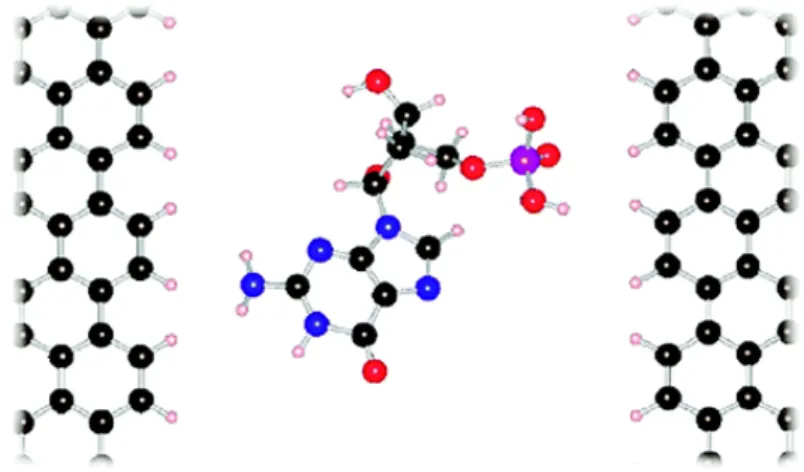
For another publication, Jariyanee Prasongkit et al. [4] have performed similar simula- tions with a graphene nanogap as illustrated in figure 7.
Figure 7: Illustration of the graphene nanogap, as studied by Jariyanee Prasongkitet al.
[4]. The two ZGNRs with a gap width of 1.47nm contain a single nucleobase in their center while the tunnelling current is being measured.
The system consists of two ZGNRs on the sides with a single nucleobase in the middle.
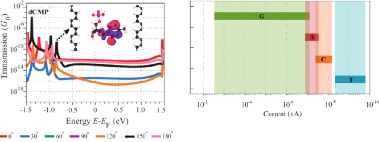
The edge carbon atoms are passivated by Hydrogen and the gap width is 1.47nm, mea- sured from one H-atom to the other. Unlike for the system with the graphene nanopore from the previous chapter, where we measured the modulation of the edge currents, we now measure the tunnelling current through the nanogap. What Jariyanee Prasongkit et al. did was calculating the so-called Transmission function T, which in principle tells us about which energy ”channels” the electrons can use in order to move through the material, thus conducting a current. Similar to the previous setup, they once again studied the system different for different rotations of the nucleobase within the gap, as shown in figure 8 on the left. This procedure was also done for different gap widths
Figure 8:Left: Transmission function of the graphene nanogap system for different rotational states of cytosine. Right: Current bandwidth of the different nu- cleobases for different rotations and positions within the gap.[4]
and different positions of the nucleobase within the nanogap, and once again they got a bandwidth out, which is shown in figure 8 on the right. Once again we can see that the bandwidths to overlap in some cases, but still it should be possible to use this kind of setup for DNA sequencing. But if we look at the magnitude of the current, we can see that in experiments, noise from the experimental setup will probably make measuring these kinds of currents very hard.
4.3 General remarks
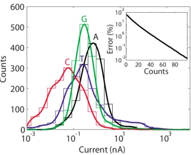
Figure 9: Current distribution for the different nu- cleotides in a 1.25nm electrode spaced pore at bias voltage of 1V with a transverse con- trolling field. The inlet shows the error of misidentifying a base versus the number of independent measurements [8]
This leads us to one of the biggest problems of these kinds of setup - noise. Experiments have shown that the brownian motion of the DNA and the pore, as well as thermal noise from the rest of the setup, make it much harder to identify a nucleobase within the pore.[12] What really helps coping with this problem is sta- tistical measurements and par- allelized sequencing. So what we can do is simultaneously se- quence lots of DNA strands in or- der to get reliable results on the sequence. Figure REF shows how sampling the same sequence over and over again makes it possibly to clearly identify the sequence of the bases. Another big problem is the translocation velocity of the DNA, which can only hardly be controlled. If the translocation velocity is too high, it will ren-
der making good measurements impossible.
So we can see that there’s already some problems originating just from the sequencing device itself, even if we haven’t really looked into the technical difficulties that can arise when it comes to manufacturing these pores and really using them.
5 Summary
What we have seen is that the NEGF formalism, together with the DFT, provides a sound concept for quantum mechanical transport simulations, and that it can help performing simulations that could lead us to new technologies. Also, we could see that in principle the DNA bases should be distinguishable with the two presented devices.
However, there are many technical difficulties yet to overcome. The goal of a $100 genome doesn’t seem too far off.
References
[1] https://www.researchgate.net/file.PostFileLoader.html?id=549285f1d3df3e197b8b46b2
&assetKey=AS%3A273654397505551%401442255702003
[2] Supriyo Datta (2013), Nanoscale device modeling: the Green’s function method, https://nanohub.org/resources/19564
[3] Kamal K. Saha, Marija Drndi´c, and Branislav K. Nikolic,DNA Base-Specific Mod- ulation of Microampere Transverse Edge Currents through a Metallic Graphene Nanoribbon with a Nanopore, Nano Lett., 2012, 12 (1), pp 50–55
[4] Jariyanee Prasongkit, et. al, Transverse Conductance of DNA Nucleotides in a Graphene Nanogap from First Principles, Nano Lett., 2011, 11 (5), pp 1941–1945 [5] https://www.genome.gov/10001772/all-about-the–human-genome-project-hgp/
[6] https://www.genome.gov/images/content/costpergenome2015 4.jpg [7] https://en.wikipedia.org/wiki/Sanger sequencing
[8] Michael Zwolak, Massimiliano Di Ventra Physical approaches to DNA sequencing and detection, Rev. Mod. Phys. 80, 141 (2008)
[9] https://de.wikipedia.org/wiki/Desoxyribonukleins¨aure
[10] P. Hohenberg, W. KohnInhomogeneous Electron Gas, Phys. Rev. 136, B864 (1964) [11] M. Paulsson,Non Equilibrium Green’s Functions for Dummies: Introduction to the
One Particle NEGF equations, arXiv.org cond-mat/0610247 (2002)
[12] Massimiliano Di Ventra, Masateru Taniguchi, Decoding DNA, RNA and peptides with quantum tunnelling, Nature Nanotechnology 11, 117–126 (2016)
[13] Po-Hao Chang, Haiying Liu, Branislav K. NikolicFirst-principles vs. semi-empirical modeling of global and local electronic transport properties of graphene nanopore- based sensors for DNA sequencing, J. Comput. Electron. 13, 847 (2014)
[14] https://de.wikipedia.org/wiki/Basenpaar
[15] http://patapsco.nist.gov/imagegallery/imageid=1490
![Figure 1: Chemical structure of a double-stranded DNA, with the sugar-phosphate back- back-bone additionally marked with a solid ribbon[9].](https://thumb-eu.123doks.com/thumbv2/1library_info/3995127.1539997/3.892.210.679.111.269/figure-chemical-structure-double-stranded-phosphate-additionally-marked.webp)
![Figure 3: A The system consisting of the central device connected to two semi-infinite leads and B the procedure scheme to analyse the system [2]](https://thumb-eu.123doks.com/thumbv2/1library_info/3995127.1539997/4.892.184.695.389.662/figure-consisting-central-device-connected-infinite-procedure-analyse.webp)
![Figure 4: Graphene nanoribbon with an embedded nanopore, a DNA molecule in the middle of the pore, and the two electrodes on the sides.[4]](https://thumb-eu.123doks.com/thumbv2/1library_info/3995127.1539997/6.892.217.673.643.932/figure-graphene-nanoribbon-embedded-nanopore-molecule-middle-electrodes.webp)