www.emea.mhps.com Integrated Power Generation Solutions
Mitsubishi Hitachi Power Systems Europe supplies up-to-date, efficient products. We construct most modern power plants and Waste-to-Energy plants. And we deliver reliable and cost- effective service solutions. Our green technologies – in energy storage and biomass, for instance – are examples for our innovation capabilities. Intelligent power generation solutions require know-how and experience. Mitsubishi Hitachi Power Systems has them both – making us a globally successful energy plant constructor and service provider.
Joint Forces
Sewage Sludge
Solutions of Sewage Sludge Mono Combustion with an Integrated Rotary Kiln
in an Existing Waste to Energy Plant
Bernhard Zimmermann, Martin Ehmann and Alexander Simon
1. Purpose of the system ...518
2. Description of the existing waste to energy plant ...518
3. Sewage sludge mono combustion ...519
3.1. Sewage sludge characterization ...519
3.2. Rotary kiln ...520
3.2.1. Drying of the wet sewage sludge ...521
3.2.2. Expulsion of gas volatile fuel constituents from the sewage sludge ...521
3.2.3. Combustion of dried sewage sludge ...521
3.2.4. Reduction of the residual carbon in the ash ...521
4. Connection of WtE plant with rotary kiln ...522
4.1. Hot flue gas extraction point ...522
4.2. Other results from CFD simulation...522
5. Measures to reduce TOC ...523
5.1. Optimized rotary kiln design and operation ...523
5.2. Insertion of lifters in burn out area ...525
5.3. Post combustion ...525
5.3.1. Ash feeding to post combustion chamber ...526
5.3.2. Ash recirculation to kiln...526
6. Post combustion system ...527
6.1. CFD simulation of post combustion chamber ...527
6.2. Drop tube test ...528
7. Summary ...528
8. Literature ...529
Sewage Sludge
1. Purpose of the system
In Germany two million tonnes (dry material) of sewage sludge is produced by waste water treatment plants. In 2010, more than 52 % of the sludge was thermally treated [7]. The phosphor content of sewage sludge is about 7 to 8 % of dry matter (as P2O5) and remains mostly in the ash after combustion. Consequently, the ash is a secondary phosphor source. Approximately 12% of the annually consumed mineral phosphate fertilizer could be covered by this [6]. For this reason, the co-combustion is not suitable because of the loss of phosphor and should be replaced by mono-combustion systems in order to save the phosphor. This is considered in the change within the regulation of sewage sludge treatment and the market will react accordingly.
For this reason, Energieversorgung Offenbach AG (EVO) is planning the construction and operation of facilities for the treatment of sewage sludge to optimize the recovery of phosphor. The following solution describes a rotary kiln mono-combustion system which will be integrated in the waste to energy plant. The purpose of the project is on the one hand, the thermal utilization of sewage sludge by using the energy bound in the sewage sludge and on the other hand to enable the recovery of phosphor from sewage sludge.
The goal is to burn approximately 80,000 t/a of sewage sludge. Two rotary kilns will be installed and connected to the combustion chamber and the first pass of two units. A rotary kiln reference plant with similar technology exists at erzo Oftringen, Switzerland since many years already. But the request of low Total Carbon Content (TOC) in ash is lower for the Offenbach project.
For this reason, additional post combustion systems are described (Chapter 6). These are concept ideas to extend the sludge combustion system for further reduction of TOC.
2. Description of the existing waste to energy plant
The waste to energy plant was built in 1995/97. It was designed for low and medium municipal waste heating values. Therefore a co-current combustion system equipped with a roller grate was installed.
From the waste bunker, the feeding hopper is loaded with waste by special grippers, which is then directed via a water-cooled waste collection chute to the hydraulically operated waste feeder which regulates the waste to the combustion chamber. The waste is burned on a roller grate. The roller grate is equipped with six grate rollers, whose speed can be controlled individually.
The walls are designed as tube walls with tailed brickwork. For the operation of the plant with sewage sludge incineration a minimum waste heating value has to be considered.
The combustion air to the furnace is divided into primary and secondary air. The primary air is fed below the roller grate over the six air zones and fed according to the requirements of the demanded air distribution. The secondary air is injected into the flue gas at the end of the combustion chamber at the beginning of the first flue gas pass by using rows of nozzles on the boiler front and rear wall.
Sewage Sludge
The boiler is a two-pass boiler with an empty vertical first flue pass and a horizontal second pass with evaporator and super heater heat exchangers. The economizer down- stream of the super heaters is also designed as horizontal pass.
For start up and shut down of the boiler as well as to support the minimum operating combustion conditions two gas burners in the first pass and an additional one in the ignition zone are installed. The furnace has a nominal capacity of 28.1 MWth, producing 31.6 t/h of live steam.
support burner
roller grate
first path ignition burner
waste chute
feeder
So far, the sewage sludge was co-incinerated in the roller grate combustion. Usually, the proportion of co-incineration was from 5 % to a maximum of 10 %, whereby the influence on the firing was noticeable.
3. Sewage sludge mono combustion
In this process, hot flue gas is extracted from the afterburning zone in the first boiler pass of a waste incineration plant to use it as a heating medium for a rotary kiln com- bustion. The hot flue gas is used to dry and incinerate the sewage sludge in the rotary kiln. The flue gas is cooled down by the drying of the sewage sludge and returned to the waste incineration furnace. An ID-fan is used for this.
3.1. Sewage sludge characterization
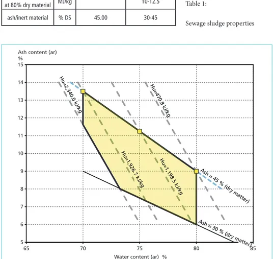
For the design of a sewage sludge incineration, a quality range and a medium sewage sludge composition has been defined to provide a basis and defined ranges for the design of the aggregates and components. The following values are used for the design:
Figure 1:
Schematic diagram of firing system MHKW Offenbach
Source: Euler, T.: Ressourcenschutz in der Abfallwirtschaft – MVA-Aschen als Sekundärrohstoffquelle für Metalle.
Bachelorarbeit zur Erlangung des Grades Bachelor of Engineering.
Sewage Sludge
Figure 2: Sewage sludge, ash and water content range
3.2. Rotary kiln
The rotary kiln will be operated in parallel to the already existing grate firing and uses the boiler, as well as the flue gas cleaning of the existing plant. The sewage sludge was already co-incinerated in the grate combustion, so boiler and flue gas cleaning are already designed for the increased flue gas mass flow.
The incineration of the sewage sludge takes place in counter-current to the flue gas taken from the grate combustion. The amount of burnt sludge is in the range of 3,75 to 6,25 t/h.
Unit Design Design range
ash/inert material % 11.25 10-15
water % 75.00 70-80
dry material % 25.00 20-30
ignition loss % DS 55-70
lower heat value
at 80% dry material MJ/kg 10-12.5
ash/inert material % DS 45.00 30-45
Table 1:
Sewage sludge properties
5 6 7 8 9 10 11 12 13 14 15
65 70 75 80 85
Ash content (ar)
%
Water content (ar) % Hu=470.8 kJ/k
g
Ash =
45 % (dry matter) Hu=1,9
26.7 kJ/kg
Hu=1,198.5 kJ/kg Hu=2,340.0 kJ/kg
Ash =
30 % (dry ma tter)
Sewage Sludge
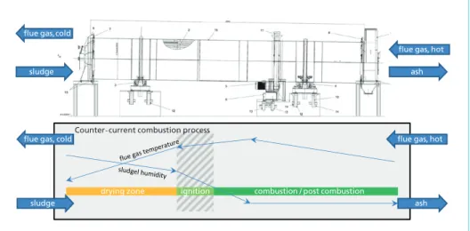
The 850 to 1,050 ° C hot flue gas from the grate combustion is fed as heating medium to the rotary kiln and is used for the following process steps in flow direction (Figure 3).
sludge
flue gas, hot
ash flue gas, cold
drying zone ignition combustion / post combustion Counter-current combustion process
sludge
flue gas, hot ash flue gas, cold
Figure 3: Rotary kiln drying, combustion and burn out principle process
3.2.1. Drying of the wet sewage sludge At the flue gas outlet the sewage sludge is fed into the rotary kiln. The sludge is dried in the dryer section by means of the hot flue gas. The flue gas cools down because of the evaporating water from the sewage sludge.
3.2.2. Expulsion of gas volatile fuel constituents from the sewage sludge The sewage sludge is heated up by the hot, low-oxygen flue gas and during heating gas-volatile constituents are released. Since there is no oxygen expected in the flue gas, there is no reaction of the gas-volatile constituents from the sewage sludge. It is desired to achieve maximum pyrolytic decomposition of the dried sewage sludge.
3.2.3. Combustion of dried sewage sludge The excess air of the overall process is sub-stoichiometric. The combustion refers to the conversion of the available residual oxygen with which just a part of the volatile gas constituents is already converted in the rotary kiln.
3.2.4. Reduction of the residual carbon in the ash The carbon content in the ash has to be reduced as much as possible in order to meet the various requirements (approval, exploitation contracts, etc.). Measurements on an existing plant [3], which is not optimized in terms of burnout quality, have shown that the TOC is usually in the range of 5 to 10 %, sometimes even beyond at kiln outlet.
Sewage Sludge
This is the starting point to optimize the process by increasing the residence time and oxygen availability of the ash particles. The potential improvement due to installation of internal lifters and resident time are to be determined by trial operation on a rotary kiln in a pilot plant. If the target reductions cannot be achieved, additional processes have to be applied.
The method steps described here are shown separately to simplify the process. In practice, the individual process steps seamlessly overlap or overlap.
4. Connection of WtE plant with rotary kiln
For the above mentioned processes it is necessary to pass hot flue gas from the furnace through the rotary kiln and if necessary through the post combustion chamber. The best point of flue gas recirculation outlet from the furnace to the rotary kiln is determined by utilizing CFD simulations taking into account layout constraints. These simulations were performed by InPro-Consult as this company performed former simulations of the waste to energy furnace considered here.
4.1. Hot flue gas extraction point
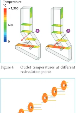
To start CFD simulations a first extraction point (1) was defined near to the rear wall where currently the hot streaks are locat- ed. In consideration of the returning gas flow it turns out that the hot streaks will move to the front wall and the tempera- ture at the first defined point was too low.
Moving the recirculation down to point (2) improves the situation, as can be seen in Figure 4.
Figure 4: Outlet temperatures at different recirculation points
4.2. Other results from CFD simulation
CFD simulations also resulted in the opti- mized arrangement of product gas nozzles as double nozzles with air inside the nozzle and surrounding process gas (Figure 5).
This ensures the best mixture between secondary air, process gas and the other flue gas from the waste to energy furnace.
process gas secondary air
Figure 5: Nozzles for process gas and secon- dary air
> 1,300 Temperature
°C
600
0
1 2
Sewage Sludge
5. Measures to reduce TOC
Firstly it is important to understand what influences the TOC content of ash at kiln outlet. The real process is complex and has been simplified to get a manageable approach for model calculations in the burn out area. The drying and combustion zone inside the kiln is not considered in this approach.
To reduce TOC in ash, intensive contact of ash particle surface with hot oxygen rich atmosphere (extracted hot gases from incinerator) is needed in order to burn C to CO or CO2. In the following approach the key figures of the carbon conversion rate are the ash active layer surface to hot gases (AB) and the mean residence time τ of ash inside kiln burn out zone. The influence of ash particle size distribution is neglected and deemed to be constant. The key question is: Can the rotary kiln burn out zone be optimized in design and operation to meet the requirements of the TOC limitation?
5.1. Optimized rotary kiln design and operation
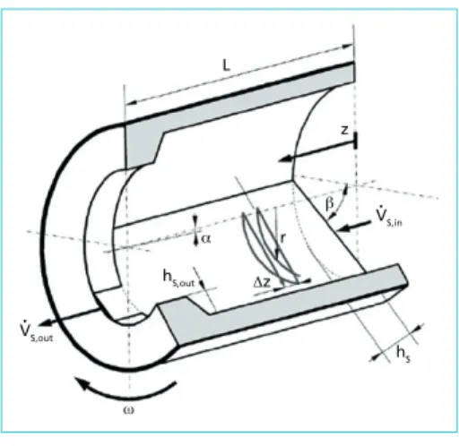
In literature [5] the transport process at slumping and rolling mode is described as follows. The ash volume flow is a function of geometric figures mainly diameter D, length L, thickness of solid bed hS and slope of kiln. The property of the solid material is considered with the angle of repose and bulk density.
(1) AS: Cross section of solid matter bed hS: depth of solid matter bed
By using the equation (1) a parameter variation was executed. The results are the cor- relation between ash surface AB, ash volume VB and residence time τ of ash in the kiln
V•S = AS•υS = 23ωR3i•
(
tan sin βα∂
hscot β •()
2hRsi 22)
23hs Ri
∂
zK = AB • VB τ
L
VS,out
z
β α
ω
Δz
•
V•S,in
hS,out
hS r
Figure 6: Section drawing of rotary kiln
Source: Ginsberg, T.: Dynamische Modellierung von Drehrohröfen. Dissertation RWTH Aachen, Fakultät für Maschinenwesen, 26.11.2010.
burn out area. In order to find a simplified link between these operating parameters and TOCω at kiln outlet the following reaction number K is introduced:
(2)
The knowledge of kiln dimensions and specific operation parameters like TOCαRef at inlet and TOCωRef at outlet of burnout area (TOCα - TOCω= ΔTOCRef) and rota- tional speed of an existing plant [3] allows to calculate a specific reaction number KRef. at this reference conditions. Using KRef allows estimating a TOCω if parame- ters are changed as follows:
Sewage Sludge
(3) Using equation 1 and 2 by varying the rotational speed leads to an approximate cor- relation between TOCω vs. Residence time τ. The results are given with the following diagram.
TOCω= TOCα, Ref •KRef –
Δ
TOCRef K-1.0 -0.5 0 0.5 1.0 1.5
5 6 7 8 9 10 11 12 13 14 15 16 17 18 19 20
0.0 0.5 1.0 1.5 2.0 2.5 3.0 3.5
Rotational Speed rpm TOC at kiln outlet
%
Mean Residence Time h 6,25 t/h 5,4 t/h 3,75 t/h Rotational speed
TOC at beginning of burnout zone 15.5 %
Sludge mass flow:
It is in agreement with the operator’s experience that with increasing sludge mass flow (equivalent to ash flow) the TOC is increasing as well. Additionally, the curve shows that the potential to reduce TOC by reducing the rotational speed is also limited.
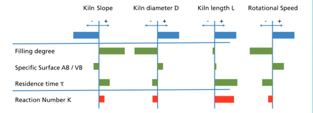
It is important to realize that the variation of parameters in order to increase the mean residence time results in a worse specific surface ratio AB/VB which is a contradictory behaviour with regard to reaction number K.
Figure 7:
Estimated TOC at kiln outlet ver- sus residence time τ and sludge mass flow
Filling degree Specific Surface AB / VB Residence time τ
Reaction Number K
- + - +
Kiln Slope Kiln diameter D Kiln length L Rotational Speed
- + - +
Figure 8: Qualitative influence of geometric parameters and rotational speed variation to reaction number K at constant ash mass flow
Sewage Sludge
The parameter which influences K the most is the length L of the kiln. However the length is mostly limited by arrangement boundary conditions. Consequently, further measures have to be investigated in order to reduce the TOC content.
5.2. Insertion of lifters in burn out area
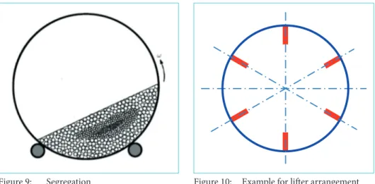
It is well known that moving of solid particles through a kiln could cause segregation.
Smaller particles could be concentrated in the core area of the solid bed.
Kiln ash taken from erzo Oftringen plant were analysed at MHPS laboratory and the results show a clear particle size distribution and no mono fraction (15 % < 0,5 mm and 40 % > 2 mm). The consequence is that segregation has to be taken into account.
Particles which stay in the core do not get into or have less contact with hot oxygen gas phase and the TOC cannot be reduced sufficiently. One measure to destroy this small particle accumulation effect or better to improve solid bed mixing is the installation of lifter devices. It is expected that lifters will increase the mean residence time [2]. This should have an additional positive effect on TOC reduction. The most promising way to find a proper lifter design is the execution of tests at a scaled down kiln test facility.
5.3. Post combustion
Another or additional measure for further reduction of TOC is the post combustion of the kiln ash. In principle this can be done by a separate process. It is beneficial to integrate this post combustion into the sludge combustion system as described above.
Two different possibilities are presented as follows. Both have the idea to grind the ash first and lead it to an entrained-flow combustion. Downstream of the kiln outlet the ash is cooled down to necessary mill operation temperature range by means of water-cooled Figure 9: Segregation
Source: Boateng, A. A.: Rotary Kiln, Transport Phenomena and Transport Processes. BH 2008.
Figure 10: Example for lifter arrangement
Sewage Sludge
screw conveyors. The mill grinds the ash to the necessary fineness range; fine enough for combustion and coarse enough for cyclone separation. The combustion takes place in a combustion chamber which is part of the hot recirculated gas ducts or directly inside the gas phase of the kiln.
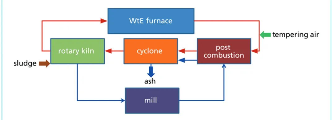
5.3.1. Ash feeding to post combustion chamber
Inside the combustion chamber the carbon of ash particles oxidises. The downstream arranged cyclone separates the ash particles from the gas phase. The separated ash represents the phosphor rich product and the gas phase enters the rotary kiln. Drop tube tests showed that the phosphor content of the ash is not reduced by the post combustion process.
WtE furnace
rotary kiln post
combustion cyclone
sludge
mill ash
tempering air
Figure 11: Post combustion chamber
The challenge of this system is to ensure that temperature of recirculated flue gas on the one hand are sufficiently hot for post combustion but on the other do not exceed melting temperature of ash at the outlet of the combustion chamber. Otherwise clog- ging of the cyclone could occur. For that reason, tempering air will be used to control suitable temperatures. This air is added upstream of the combustion chamber.
To reduce fouling of the duct system an ash-trap is foreseen which is arranged close to the extraction point of hot flue gases.
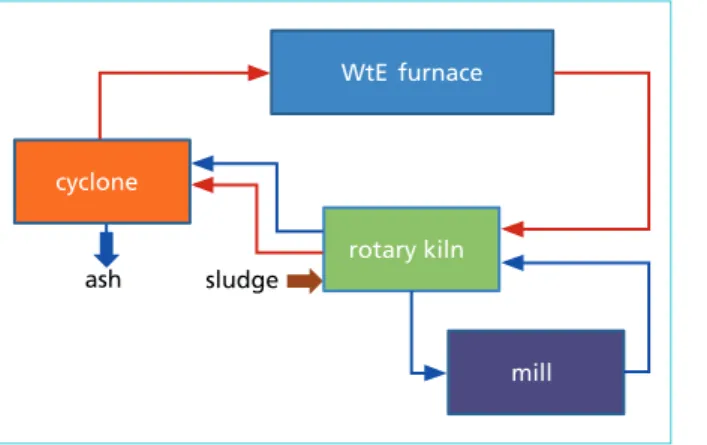
5.3.2. Ash recirculation to kiln
Alternatively, the ground ash could be injected (only a certain portion or completely) into the rotary kiln. The behaviour of carbon burnout should be similar to the com- bustion chamber mentioned above. However, before entering a cyclone the ash must pass the drying zone inside the kiln. It is expected that a certain amount of this ash is deposited from gaseous phase inside kiln and flows through the kiln again. This leads possibly to a too high filling rate and consequently, to unfavourable operation behaviour of the kiln.
Sewage Sludge
It was decided to investigate the post combustion chamber more in detail.
6. Post combustion system
In order to confirm if the concept described in Chapter 5.3.1. is realistic under burn- out aspects, a CFD simulations were performed. Furthermore, the injection system was simulated as highly simplified system. A drop tube test was performed to check, if the chosen char burnout model was sufficient to ensure the decrease of TOC in the entrained flow reactor. After all these checks the real entrained flow reactor including the constructed injection system was designed.
6.1. CFD simulation of post combustion chamber
Whilst designing the entrained flow reactor several constraints have to be taken into account. At first the temperature of the flue gas has to be that high that char reaction occurs. On the other hand it has to be ensured that the temperature of the particles inside the flow do not reach melting temperature so that the cyclone will not be blocked by slag depositions. At position (1) in Figure 13 hot recirculated flue gas flows into the post combustion chamber and at position (2) the char particles are injected. This results in cooling down the flue gas downstream of the ash injector. Downstream of
ash sludge
WtE furnace
rotary kiln cyclone
mill Figure 12:
Ash recirculation to kiln
high 1
2 3
4
5
low
temperature
mass fraction of O2
that position an increase of temperature is observed. Accordingly, the oxygen content decreases. Further downstream at position (3) the horizontal surface perpendicular to the axis of the duct the very low oxygen concentration vanishes, so that the atmosphere at the walls is oxidizing. At position (4) recirculated flue gas is injected to decrease flue gas temperature and reduce high temperature peaks efficiently.
Figure 13: Temperature and Oxygen distribu- tion inside entrained flow reactor
Sewage Sludge
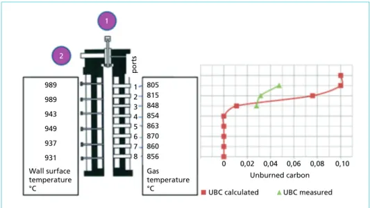
6.2. Drop tube test
Drop Tube test were performed at Ruhr-University Bochum and the same flow situation was simulated by CFD.
0 989 1
989 943 949 937 931 Wall surface temperature
°C
Gas temperature
°C 805 815 848 854 863 870 860 856 2 3 4 5 6 7 8 2
1
0,02 0,04 Unburned carbon
ports
UBC calculated UBC measured 0,06 0,08 0,10
Figure 14: Exemplary result of comparison between experiment and simulation
The drop tube furnace has one inlet for the carrier gas at (1). At position 2 the ash with TOC of 11 % is injected. The gas is heated up by electric heating. The temperatures of the heated surface are shown left of the drop tube reactor in Figure 14. The measured gas temperatures without induced ash particles can be seen right of the drop tube.
During the reaction tests samples of ash are sucked out through ports 1, 2 and 3. The resulting TOC values are plotted in the diagram on the right side of Figure 14. The resulting values from the CFD simulation are plotted as red curve. It can be observed, that the reaction starts earlier in the experiment than in the simulation. On the other hand the final TOC value stays at a higher level than in the CFD model. Nevertheless this measured value is lower than the requested 5 %.
7. Summary
The technical paper reveals that there are more opportunities for plant operators to treat sewage sludge. One of the possibilities to treat sewage sludge is to build a mo- no-incineration plant by using CFB technology. This includes a long permit procedure as well as high investment costs.
To avoid such complex effort unconventional solutions are ready and proven in prac- tice. One of those solutions is to combine a given WtE plant with a rotary kiln system by using the flue-gas of the WtE plant. This is practiced in Switzerland (plant erzo Oftringen) and has been in successful operation for 20 years.
Sewage Sludge
However, regulation of sewage sludge treatment and the requirement regarding limit value of TOC has to be fulfilled. Currently, the limit value cannot be proven by only implementing a rotary kiln system.
In order to meet this regulatory requirement MHPSE presented in this technical paper an advanced upgrade to the known technology by means of post-combustion. CFD calculation and drop tube tests of ash burnout show very promising results with a high technical potential and advantages comparing to CFB combustion systems.
Although it is expected that the reduction of TOC could be improved by adding modi- fied blades in the burn out area to avoid phenomenas like segregation.
8. Literature
[1] Boateng, A. A.: Rotary Kiln, Transport Phenomena and Transport Processes. BH 2008.
[2] Bongo Njeng, A. S.; Vitu, S.; Clausse, M.; Dirion, J.-L.; Debacq, M.: Effect of lifter shape and operating parameters on the flow of materials in a pilot rotary kiln: Part III. Upscaling consid- erations and segregation analysis. In: Powder Technology, Elsevier, 2016, vol. 297, pp.415-428.
10.1016/j.powtec.2016.04.052. hal-01486593
[3] erzo - Entsorgung Region Zofingen, KVA Oftringen: Operational Data.
[4] Euler, T.: Ressourcenschutz in der Abfallwirtschaft – MVA-Aschen als Sekundärrohstoffquelle für Metalle. Bachelorarbeit zur Erlangung des Grades Bachelor of Engineering.
[5] Ginsberg, T.: Dynamische Modellierung von Drehrohröfen. Dissertation RWTH Aachen, Fakultät für Maschinenwesen, 26.11.2010.
[6] Krüger O.; Adam, C.: Monitoring von Klärschlammmonoverbrennungsaschen hinsichtlich ihrer Zusammensetzung zur Ermittlung ihrer Rohstoffrückgewinnungspotentiale. BAM Bundesan- stalt für Materialforschung und -prüfung im Auftrag des Umweltbundesamtes, Februar 2014.
[7] Wiechmann, B.; Dienemann, C.; Kabbe, C.; Brandt, S.; Vogel, I.;Roskosch, A.: Klärschlamment- sorgung in der Bundesrepublik Deutschland. Dessau: Umweltbundesamt, 2012.
Contact Person
Dr.-Ing. Bernhard Zimmermann
Mitsubishi Hitachi Power Systems Europe GmbH Head of Process Engineering
Firing Systems & AQCS Schifferstraße 80 47059 Duisburg GERMANY +49 20380382028
b_zimmermann@eu.mhps.com
Bibliografische Information der Deutschen Nationalbibliothek Die Deutsche Nationalbibliothek verzeichnet diese Publikation in der Deutschen Nationalbibliografie; detaillierte bibliografische Daten sind im Internet über http://dnb.dnb.de abrufbar
Thiel, S.; Thomé-Kozmiensky, E.; Winter, F.; Juchelková, D. (Eds.):
Waste Management, Volume 9 – Waste-to-Energy –
ISBN 978-3-944310-48-0 Thomé-Kozmiensky Verlag GmbH
Copyright: Elisabeth Thomé-Kozmiensky, M.Sc., Dr.-Ing. Stephanie Thiel All rights reserved
Publisher: Thomé-Kozmiensky Verlag GmbH • Neuruppin 2019 Editorial office: Dr.-Ing. Stephanie Thiel, Elisabeth Thomé-Kozmiensky, M.Sc.
Layout: Claudia Naumann-Deppe, Janin Burbott-Seidel, Sarah Pietsch, Ginette Teske, Roland Richter, Cordula Müller, Gabi Spiegel Printing: Universal Medien GmbH, Munich
This work is protected by copyright. The rights founded by this, particularly those of translation, reprinting, lecturing, extraction of illustrations and tables, broadcasting, micro- filming or reproduction by other means and storing in a retrieval system, remain reserved, even for exploitation only of excerpts. Reproduction of this work or of part of this work, also in individual cases, is only permissible within the limits of the legal provisions of the copyright law of the Federal Republic of Germany from 9 September 1965 in the currently valid revision. There is a fundamental duty to pay for this. Infringements are subject to the penal provisions of the copyright law.
The repeating of commonly used names, trade names, goods descriptions etc. in this work does not permit, even without specific mention, the assumption that such names are to be considered free under the terms of the law concerning goods descriptions and trade mark protection and can thus be used by anyone.
Should reference be made in this work, directly or indirectly, to laws, regulations or guide- lines, e.g. DIN, VDI, VDE, VGB, or these are quoted from, then the publisher cannot ac- cept any guarantee for correctness, completeness or currency. It is recommended to refer to the complete regulations or guidelines in their currently valid versions if required for ones own work.