Constrained Proofs:
A Logic for Dealing with Behavioural Constraints in Formal Hardware Verification*
Michael Mendlert
Department of Computer Science University of Edinburgh
Abstract
The application of forma.! methods to the design of correct computer hardware de- pends crucially on the use of abstraction mechanisms to partition the synthesis and verification task into tractable piece.s. Unfortunately however, behavioural abstractions are genuine matbematical abstractions only up to behavioural constraints, i.e. under certain restrictions imposed on the device's environment. Timing constraints on input signals form an important class of such restrictions. Hardware components that behave properly only under such constraints satisfy their abstract specifications only approxi- mately.
This is an impediment. to the naive approach to formal verification since the question of how to apply a theorem prover when one only knows appro:cimately what formula to prove has not as yet been dealt with.
In this paper we propose a notion of constmined proof and constrained proposition which provides for 'approximate' verification of abstract specifications and yet does not compromise the rigour of the argument. It is based on the idea of removing the constraints from the specification a.nd making them part of its proof. Thereby the abstract verification is separated from constraint analysis which in turn may be delayed arbitrarily. We have implemented the logic on the interactive theorem prover LEGO and verified simple examples. The presentatiou in this paper uses one of these examples for explaining the problem and demonstrating the use of the logic.
"This work was supported by the Studienstiftung des deutschen Volkes and SERC grant No.GR/F 35890
"Formal System Desigu"
tNow at University of Erla.ngen-Nürnherg, Institute for Computer Aided Circuit Design, email
mtmdler@faui77. informatik. uni-erlangen, de or mm@lfcs.ed.ac.uk
1 Introduction
Quite a Jot of work has been done to make hardware verification practicable at a non- academic scale [5,4,19,20,25]. What still seriously limits its success is the almost insurmoun- table complexity from whicl1 verification of non-trivial hardware designs suffers. First steps are being undertaken by various researchers to exploit structuring concepts such as modu- larisation and abstraction in the design of hardware to break up the verification task into a series of smaller chores, each of which can be dealt with independently {5,4,26,18,35,32,10].
The question arises how this approach should best be implemented in modern interactive theorem provers.
1.1 The Problem of Constraints
A typical phenomenon one encounters with the implementation of even conceptually simple abstraction steps which are standard practice in hardware engineering is that they cannot be formalised without introducing constraints. Constraints are assumptions about the device's environment under which the particular a.bstraction (of its behaviour) at hand is actually valid.
An example is the passage from a sequential drcuit, built accord.ing to the synchronous design pa.radigm, to its abstract description in terms of a.n input-output automa.tan. Here the abstraction is only valid as long as the environment (among other things) obeys a timing constraint which says that all input lines of the sequential circuit must be kept stable during a certain well-defined phase of the clock. Clearly, the necessity for imposing timing constraints is a general phenomenon, not restricted to the synchronous case. lt is an even more important issue in asynchronous designs. (17,34,31J.
The interaction between abstraction and constraints poses a tangled prablem. Con- straints interfere with the essential idea of reasoning about a behaviour in abstract terms which is to avoid details specific to the implementation at the more concrete level. For it is impossible to work with the device's ahstract behaviour without at the same time having to deal with the concrete-level constraints on which it depends. To verify, for instance, that the behaviour of a composite device meets its abstract specification it does not suffice simply to compose the abstract specifica.tions of its components. The verification also has to show that at the concrete 1evel the composition does not violate the constraints of each component. This, in general, will make it necessary ta impose constraints again on the environment of the composite device.
Thus, constraints defeat the idea of top-down refinemcnt, which is first to decompose
a systern into components at the abstract level and then independently to implement each
component at the concrete level; Verifying constraints requires knowledge bath of the overall
structure of the system ( the environment of a component) from the abstract level and of
the imp1ementation (the canstraints of a component) at the lower level. In shart, the
general situation in the modeling of h_a.rdware seems tobe that of incomplete abstractians,
i.e. abstractions modulo constraints. The constraints an wllich the abstraction depends
embody residual aspects of the concrete level that impinge an the subsequent design and
cannot be a.bstracted away once and forall.
1.2 A Possible Solution
The best one can expect here is to find means by which reasoning about abstract behaviour and constraint analysis fall into two separate verification passes rather than having them intertwined as the straight-forward approach suggests. The goal of this paper is to intro- duce and justify a logic in which the main verification of an abstract behaviour is truly an abstract verification in that it does not have to be concerned with constraints. It pro- ceeds hy assuming a successful constraint analysis wherever it depends on constraints. In the course of this main verification information about the constraints is accumulated as a proof obligation to be filled in at a later stage. Ideally, the remaining verification task corresponding to constraint a.nalysis would then be handed over to a specialised tool. In some cases it could he clone automatically, for instance extracting the minimal clock period for a synchronous system. In other cases, where the logic is undecidable, it has to be done manually. An example of this would be proving that the output of a certain integer function lies within a given finite range.
The idea leading to the proposed logic presented in this paper is not new. It refiects good engineering practice: In a first approximation one tries to establish the feasability of a design. Only tlten is it worthwhile to attempt a complete validation in a second step.
New however, is the attempt to formalise this engineering principle mathematically and to implement it at the root of a theorem prover.
We have implemented an experimental prototype ofthe logic with the help of the me- chanical proof checker LEGO [29]. LEGO provides a bed for encoding natural deduction style logics in the type theory of the Logical Framework (LF) [16] or the Calculus of Con- structions (CC) [6,7] plus some extensions. We have used an extension of CC [22] which, as the most prominent feature, provides E-types, i.e. a generalisation of ordinary pairing where the type of the second component in a pair may depend on the value of the füst component ( ordinary pairing is the special case in which the types of both components are independen t from their respective values). The following will show that i t is in fact the 'E- types that make it possible to cut out and delay constraint analysis, so that the main proof can be performed without looking at or even manipulating constraints. lt merely records necessary information about what has to be proved later, when one turns to analysing the constraints.
lt is outside the scope of this paper to give an introduction to LEGO and to present the implementation in detail. Iustead, we will use an informal mathematical language which, as we hope, will serve to explain the underlying idea in a compact and ludd way. We would like to stress that everything presented in this paper actually can be done interactively, modulo syntax, with the LEGO system even wl1ere we do not mention it explicitly.
2 Constraints and Synchronous Hardware Design
We are going to explain the implemented logic by means of a simple example that is just
complex enough to convey the basic idea. As the area of hardware design where the example
is taken from we have chosen the particular form of temp~ral abstraction that is fundamental
to the design of synchronous hardware. Let us first briefiy explain the general situation
(Section 2.1) and then turn to a concrete exa.mple (Section 2.2).
2.1 Synchronous Circuits
A typica.l synchronous circuit is built up from latche8 (such a.s D-type fl.ipfl.ops) and combi- national circuits (such as nand gates, inverters, and nets thereof). In a slightly simplified
view 1 one can summarise the essence of the synchronous design paradigm in the following design rules:
Cl All latches are triggered by a common clock signal C2 There is at least one latch in every feedback loop
C3 The clock period is long enough to allow for signal changes caused by any clock event to settle throughout the circuit before the next clock event
C4 The inputs to the circuit have to be stable long enough prior to any cJock event for signals to have become stable by the dock event.
In a broad sense all of these design rules can be interpreted as constraints, more precisely, Cl-C2 as structural constra.ints and C3-C4 as behavioural constraints. From a verHi.cation point of view the structural constraints Cl-C2 are essentially refiections of internal beha- vioural constraints, i.e. they are conditions necessary for verifying that no behavioural constraints are violated by components within the circuit.
Muc.h of the success of the synchronous design style is due to the fact that under the design rules Cl-C4 one does not need to consider propagation delays when reasoning about the circuit's behaviour. If one is interested in the state of the circuit only at every clock event ( or during a certa.in interval around it) an.d records the evolution of input and output values at these points, then the descriptive effort can be drastically reduced:
Al Latches behave like unit delays
A2 Combinatorial circuits behave like delay free boolean functions
A3 Tlte complete synchronous circuit reduces to a finite automaton and the automa.ton's behaviour can be derived by composing unit delays and delay-free boolean functions.
More precisely, every unit delay gives rise to one state variable and the state transi- tion function is determined by the interconnection of state variables through boolean functions.
Thus, relativising the synchronous circuit's behaviour to the abstract time given by the succession of clock events abstracts from propagation delays. Note, that the restriction on dock events can also he viewed as part of the design rules and as a constraint on the usage of the circuit which is characteristic to synchronous abstraction.
Although, either implicitly or explicitly, timing abstraction has always been used in the design of synchronous systems (36,3,8,23], it seems that first attempts to formalise it for the purpose of verification have only recently been made [26,18]. The separation of design rule checking (Cl-C4) from reasoning in abstract terms (Al-A3) is crucial for pra.ctical applications, but there seems to be no sa.tisfactory implementation of this separation on an interactive theorem prover. For instance, Herbert's methodology (18], implemented on
1
We ignore here, among other things, for the sake ol simplicity set-up a.nd hold times of latches or the
possibility to use multiple docks. This does not, however, a.ffect the point.
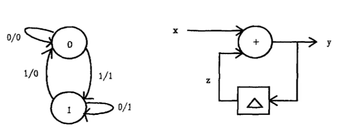
Figure 1: xor-gate and level triggered latch
the proof checker HOL [11,12], though it conceptually distinguishes between statements about timing and abstract behaviour, leaves both aspects intertwined at the level of proofs.
This basically mean.s that design rule checking an.d reasoning in abstract terms have to go together in a single proof. The logic presented in this paper provides a way to separate these concerns within a single logical inference system.
2.2 A Simple Circuit Design
Let us turn to a specific example. Take the simple case of a combinational circuit such as a '.x:or' gate and a level triggered latch (Figure 1) which, as in [18), are to be considered as components of a synchronous system; i.e. they are put into an environment with a global clock, relative to which certain conditions on the stability of inputs can be imposed as timing constraints to allow timing abstra.ction.
Their behaviour can be described by predicates over input and output signals. For simplici ty we take signals to be functions from integers to booleans, i.e.
signal = int - bool
Assuming that both gates have constant propagation delays Oxor > 0 and 0/atch > 0, their behaviour rnay be defined by the following axioms:
xor(x,y,z) 'M Vt: int. z(t + Oxor) = ü + yt
latch (d,c,q) 'M Vt: int. (et= 1:>q(t+61atch) = dt) f\
(et:::: 0 ::> q(t + O/atch) == q(t + Otatch - 1))
Note, that we are using the operator + both for addition over int as weil a.s for modulo- 2 sum over bool. According to the a.xioms the xor-gate perforrns the modulo-2 sum of its inputs x, y at every time step and outputs them with a delay l>xor on output z. The latch is enabled to pass data from input d to output q with a delay 81atch by positive levels of the clock input c, and it is locked when et == 0.
For the purpose of this paper these simple a.x:ioms are assumed to be the low·level, most detailed, description available for the components xor and latch. Clearly, they are already an abstraction of real devices' behaviours. A more realistic description would ha.ve to account for variable gate delays as weil as setup and hold times for the latch; it would perhaps assume continuous rather tha.n discrete time and signal values, require maximal signal rise
and fall times, and so on. Since for describing our logic it is of no importance how detailed
a model of behaviour one actually starts from we 11ave taken the simplest ax.ioms possible.
The reader is referred to [2,14] for a discussion of more sophisticated a.x.iomatizations of elementary digital circuits.
Tl1e important thing to note is that xor and latch contain both timing ( delays) a.nd functional aspects ( operations on booleans) intertwined. In a synchronous design context, however, where one takes advantage of the design rules, one expects not having to ca.re about delays. More precisely, the xor-gate should behave like a delay-free boolean function and the latch like an one-unit delay (Al-A2). Therefore, in place of xor and latch one would rather work with axioms like
xor _syn (x, y, z) latch_syn ( d, q)
'Vt : int. zt = xt + yt
lr/ti,t2: int. next (t1, t2) :) q(t2) == d(t1)
(1) (2) where next (t 1 , t 2 ) is a predicate expressing that t 1 and t2 are two consecutive points in time. lt is defined abstractly 2 by
In this abstract view the clock does no langer appear as an input to the latch. For in a synchronous circuit the latch's clock input is always connected to the global clock signal and consequently no longer availab]e as an input. Thus, assume a clock signal
clk: signal
which is globally defined throughout the system. As a result clkmay be used within formulae without it being mentioned explicitly as a parameter.
Obviously, :eor_syn, latch_syn cannot be proved from xor and latch right away sjnce the delays cannot be wiped out. What can be proved, however, by introducing constraints are certain approximations thereof. Before we can state them we need some predicates for formulating constraints. We first assume tltat clock tkks are marked by rising edges of clk and de:fine a corresponding predicate
tick i f1. clk( t - 1) = 0 /\. clk( t) = 1
which obtains true if there is a clock tick at time t. Given this predicate one may define what it means that a signal x is stable in all intervals of length li prior to clock events:
Finally, for constraining the clock we have two other predicates, the first expressing that the 1-phase of the clock lasts exactly one time step, and the second imposing a minimal distance li on two cousecutive clock ticks:
one_shot 'f!: 'r/t:int.clk(t)=l .::> (clk(t-1)=0/\ clk(t+l)=O) min_sep b <ff: 'Vt1, t 2 : int. (t1 < t2 /1. tick t1 /\ tick t2) :::> t2 ~ t1 + li
2
0ne might want to turn the predicate next into a. function which for time t yields the successive time
step next(t) and is undefined otherwise. In a logic with partial terrns this could be done using the so-called
i-operator which we do not have avaiiable in LEGO.
With these predicates put into place the promised approximations of xor_syn and latch_syn can be formulated:
xor _abs ( x, y, z) 'ff:: stable x 6:r:or /\ stable y 6xor J 'Vt : int. tick t :J zt = xt + yt
latch_abs (d, q) rf:t (one..shot /\ min...sep 61aich) J Yt1, t2 : int.(tick t1 /\ tickt~
:J (next_abs(t1, t2) :J q(t2) = d(t1))) where nexLabs is the following approximation of next:
The bold-faced parts indicate the o:ffset of the approximations from the ideal versions xor_syn and lalch_syn. This offset explicitly reflects the design rules (C3-C4 ): timing constraints on inputs, on the clock signal, and the sampling at clock events. In contrast to xor_syn, latch..syn these· approximations now can be derived from axioms xor and latch, i.e. we have
xor(x,y,z) f- xor_abs(x,y,z) latch (d, clk, q) 1- latch_abs (d, q)
We state this without proof here. The gap will be filled later when we have introduced the logic. Note, that due to the simplification of the latch's behaviour (i.e. no set-up and hold conditions) latch_abs does not require stability of data input d relative to the clock.
The observation that stability constraints essentially work to squeeze out delays of the behavioura1 description and thereby separate timing behaviour from functional behaviour is already employed in [18,26]). Here we push this idea further so as to also encompass constraints on time points, i.e. tickt. Being restrictions which also refl.ect the design rules, constraints on time points should be subjected to the same treatment as are stability constraints on signals. In fact, our logic will also deal with this type of constraints.
Now suppose as a simple design task, we wanted to build a stoppable modulo-2 counter.
It is to have one input and one output, and to produce a stream of alternating Os and ls as long as the input is at 1 and stop at the current output value when the input switches to 0. More formally, its behaviour is specified by the following 1ogicaJ formula:
cnt_spec (x,y) 'M 'Vt1,t2: int. next_abs(ti, t2) J y(t2) = x(t2) + y(t1)
From this input-output specification one derives easily a Moore automaton or equivalently an implementation consisting of an exclusive-or function and a one-unit delay as depicted in Figure 2. Given, that xor_syn (1) describes the behaviour of the exclusive-or and latch_syn (2) that of the one-unit delay, the behaviour of the implementation is given by
cnt_syn(x,y,z) ~ xor_syn(x,z,y) /\ latch_syn(y,z) (3)
which em ploys logical conjv.nction /\ of predicates to express composition or sv.perposition of
two beha.viours. Another important operation on behaviours is hiding of internal wires which
logically is achieved by existential quanlification. Since in tl1e example the specification of
the counter describes a circuit with one input and one output we have to consider signal
z as intemal in the implementation (3), i.e. x and y are the required input and output
0/0 X y
z 0/1
Figure 2: Implementation of the modulo-2 counter
signals visible to the envirorunent. Verifying that the implementation is correct would now amount to proving that a.fter hiding of the internal signal z the implementation (3) entails the specification, i.e.
3z: signal. cnLsyn(x,y,z) 1- cnt_spec(x,y) (4) This would be an easy exercise invoking the rules of ordinary first-order logic. Unfortunately, applying synchronous abstraction to xor and latch does not provide an ideal exclusive-or or an ideal one-unit dela.y satisfying xor_syn and latch_syn but merely approximations xor_abs and latch_abs. Therefore the implementation we are actually able to get is
cnt_abs(x,y,z) g xor_abs(x,z,y) /\ latch_abs(y,z)
Of course there is no reason to expect that 3z : signal. cnLabs (x, y, z) entails cnLspec (x, y).
Rather, in place of the original cnLspec, we will again only achieve an approxima.tion, perhaps something of the form
cnt_appr (x, y) ~ (C
0A C1 (:z:, y )) :J (Vti. t2 : int. C
2(t
1 ,t
2 ):::> (nexLabs (t1, t2) :J y(t2) = x(t2) + y(t1)))
where Co, Ci, and C 2 are constraints that have to be imposed on the composite circuit to allow the envisaged derivation
3z : signal. cnt_abs ( x, y, z) t- cnt_appr ( x, y) (5)
Here we are facing the question of how to go about finding the constra.ints C 0 , C 1, C 2
and thus the modifi.ed specifica.tion cnt_appr. The straightforward approach, as employed
for instance in [14], is attempting a derivation of cnt..spec (from cnLabs), finding out where
it fäils, and at each such dead end identifying a.ssumptions that would make it work if tliey
were available in the first place. This information can then be used for determining the
constraints C 0 , Ci, C 2 and the place where they have to go to weaken the specification
appropria.tely. This is however not quite satisfactory since it means going through the
verification proof twice, once for finding the constraints and a second time after pasting them into the spedfication for completing the proof. Furthermore, and more importantly, the proof has to intermingle timing constraints with abstracted properties; it aims to prove the abstract specification cnt..spec while at the same time having to deal with the constraints inside the propositions xor_abs, latch_abs, 'next_abs, and cnLappr.
As argued before, this is not what one really would like to do. Rather, one would like first to perform the abstract verification ( 4) without consideration of constraints. This establishes the feasibility of the design at the abstract level. The constraints, which are dependent on a.
particular implementation mechanism -here the implementation as a synchronous circuit-, are not determined before the implementation of the abstract components is chosen. In the example, this leads to the approximations xor_abs, latch_abs. Finally, a constraint analysis should be able to use the abstract proof (4) together with the knowledge of the constra.ints contained in xor _abs and latch_abs for extracting the constraints in cnt_appr.
In the following we will show how to achieve this goal by reformulating the notions of proof and proposition so as to 'hide' constraints within them and set up a rudimentary ca.lculus of derivations to deal with this constrained logic.
3 Logic of Constrained Proofs
The logic will consist of a suitable base logic in which to express both the constra.ints and the abstraction properties of the verification example. For the purpose of our particular example it is sufficient to assume a formal system for typed fi.rst order logic. lt is not really essential what the base Jogic looks like as lang as it fuliills certain minimal requirements which we set out below. This base logic will then be extended by a new syntactic operator [. J for 'hiding' constraints. Tlte described logic of constrained proofs therefore need not be seen as a particular and fixed Iogic but rather as a method for extending ones favourite logic for accomodating constra.ints.
In the following we assume some familiarity with natural deduction style logics and the lambda calculus (with explicit pairing) as a simple functional programming language.
3.1 Base Logic
Of the base logic we will require logical connectives for conjunction <f>/\ t/J, implication </> :::> 'l/J,
universal and existential quantifica.tion Vx : A.</>, 3x : A.</> together with the usual natural deduction rules
VEt: </>{t/x}
Vx: A.4>
/\E :-</>- 1 </JA'lj;
v I . Vx : A. </J
V X•
</> 31 . 3x: A.<J>
t • <f>{t/x} 3Ex:
:>I:
3x : A. </> 'l/J
Here <P{tjx} denotes the substitution of term t for variable x in</>. Additionally, the logic comprises negation •</>, disjunction </>V t/J, the propositional constants T for true and .L for contradiction with rules
cP V 1/J
Vlz ;-</>-
-,f:
VI . </>V tP
r • t/J
-.E : </> .L -.<f>
</>1 V </>2 VE:
.LE :±. .L TI·- • <P T
These rules are to be understood in the usual way in what regards free and bound variables, substitution of a term for a free variable and the variable restrictions associated with rules Vlx and 3Ex. In 'r/Ix, x must not occur in any assumption on which </> depends, and in 3Ex, x must not occur in t/J or in any other assumption save </> on which the lower occurrence oft/; depends. The letter I in the name of a rule stands for 'introduction' and E for 'elimination'.
For (refinement) proofs these rules are read top-down, i.e. they reduce proving the proposition above the rule bar to proving the propositions below it. In what follows all rules are written in this top-down way. It is useful to have syntactic definition ava.ilable in the logic as a means for abbreviating a complex formula by some user-defined name possibly with syntactic parameters. Definitions also have their introduction and elimination rules, e.g. a definition <fl 'f1 </> is acompanied by rules
dp·<P' . """i d/E::,
For the logic of constrained proofs we will not only have to treat propositions but also proofs as mathematical entities which are manipulated by the inference system. All modern interactive theorem provers, likc HOL, VERITAS, LAMBDA, IPE [30J, ELF [13], or LEGO are hased on this principle as they are essentially programming systems for manipulating proofs. A formula is identified with the set of its proofs a.n.d a rule is implernented by a program which transforms proofs of the rule's hypotheses into proofs of its conclusion. In tliis spirit we associate with each of the above rules a program which implernents the rule bottom-up, i.e. it can be applied to proofs of the propositions below the bar to yield a proof for the proposition above it. The name of each rule will be taken to denote its associated program on proofs. Consider the rules /\[, /\E1 and /\Er. The introduction rule AI describes how to build proofs of a formula </> /1. '!/; from proofs of its components </> and t{J; it serves to introduce the junctor /\. Rules !1.E1, /\Er say that from a proof of </> /\ 1/J proofs of the components </> and 1f; can he extracted; it serves to eliminate the junctor /\..
To be more precise, a.s we are dealing with rule schemata rather than single rules we
vmuld have to instantiate each rule name with the actual propositions to denote a particular
program on proofs. For instance, we would write Al(</>, t/J) for the function which takes pairs of proofs of </J and 1/.J to a proof of <P /\ 1/J. However, since it is clear from the proofs to whicb /\-introduction is applied which instance of the schemata is meant we may simply write /\./.
The same applies to the other rules. A nice feature of LEGO is that it supports this style of polymorphism. It knows to infer the type of a function from tbe type of the arguments to whiclt it is applied (or, more generally, from the context in whicb it is used).
We do not need to know what the basic prograrns implementing the rules look like nor what exactly a proof is. All we want is compose them to form derived rules or derivations and assume tliat they satisfy certain natural equations guaranteeing that they interact in a coherent way. Of such equations only those are given below which are used in the sequel.
First some notation: The language chosen to compose and reason about derivations is essentially a typed lambda calculus with explicit pairing. To denote that p is a proof of cf>
we write p: <f> and for f a derivation of 1/J from <P we write f : </>--;. 1/J. 3 So, for instance, the (basic) derivation /\J( </>, 'ljJ) : </>X 1/J --+ <f>/\ t/J may be applied to proofs p : </> and q : 'r/; to yield a proof /\.!(</>, 'l/J)(p,q): </>A 'lj;. As remarked above this is more simply written /\l(p, q): <f>I\ 1/J.
>.-abstraction is written as usual, and o stands for the sequential composition of derivations in reversed order (which matches with the bottom-up notation ofprooftrees). The Operator
o is an abbreviation definable in terms of >i-abstraction; for instance AE1 o /\I == AX: <P x t/J. /\E1(/\l(x)) : <P x 1/;-+ </>
The equations required to hold between the hasic rules all state that an introduction rule can be cancelled by subsequent application of the corresponding elimination rule.
/\Ei o /\.l(p: </J, q: t/J) = p (6)
/\Er o /\/(p : </>, q : '1/J) = q (7)
::>E(::>l(f: q,-+ t/J), p: </>) = f(p) (8)
3Ex(3It(P: c/>{t/x}), f: </>-+ '1/J) = f{ t/x }(p) (9)
V Et o Vlx(P: </>) = p{t/x} (10)
dfE o dfl(p : </>) = p (11)
3.2 Extending the Base Logic
On top of this base logk we encode the idea of a constrained proposition proofs of which, also called constrained proofs, are allowed to have hidden assumptions. In the example hidden assumptions will be behavioural constraints. To introduce the general concept, we begin with the central definition.
Definition 1 (Motivation) Let <P be a proposition. A constrained proof of <f> is a pair c =:: (;,p-y) consisting of a proposition r and a proof of i :::> </>. The set of constrained proofs
of <P will be denoted by [ </>] and referre.d to as a constrained proposition.
The motivation for this definition in view of the envisaged application for handling constra.ints is the following: Constructing a proof c = (1, p'"Y) of a specification of the form [ efi] amounts to proving cf> under some assumption r, for instance a timing constrain t. The
3
Note the difference between p : t/J ::) l/J a.nd f : efJ -+ '!/>; in the former p is a proof, in the latter f is a
derivation (a p1ogra.m on proofs).
assumption is determined by the proof c and recorded as its first component. Given such a constrained proof c : [ <P J, one can extract both the hidden constraint 11"1 ( c) a.nd the proof
11"z(c): 7r1(c):) </>
that this constraint implies </> (11" 1 and 11"2 denote first and second projection, respectively).
The constraint 1tt ( c) may be subjected to constraint analysis and from the second component
:ir 2(c) one may build proof of <P for a.ny proof of the constraint 11"1(c) via the -:)E rule.
Definition 1 suggests to extend the base logic by a new syntactic operator [.) which for any proposition </> forms the constrained proposition ( r/> ]. This operator as we shall see should work for all proposWons, not just for those of the base logic. More precisely, we want to build propositions like
["lt: A.[<f>]],
i.e. we want to iterate the operator. As to the associated rules for [. ], the discussion above yields
[ </>) [ I] : T
..; 7
The introd uction rule [ J] says that in order to prove [ <P] we may prove <P under some assumption /, which we are free to choose 4 • Read bottom-up, ( I] says that if a proposition
cf> can be derived from some assumption '"'( then there is a proof of [ </>] which no Ionger
depends on ; . The assurnption "/ effectively is discharged in favour of the [. J construct which only indicates its presence. Note that even though the assumption "/ to be hidden by an application of [J] rnay be inferred (in LEGO) directly from the argument derivation
f: "(--+ <,b, we will supply it a.s an explicit argument, i.e. we write (IJ('r,f: 'Y--. </>) rather
t11an [ IJ(J : ; ~ <P ).
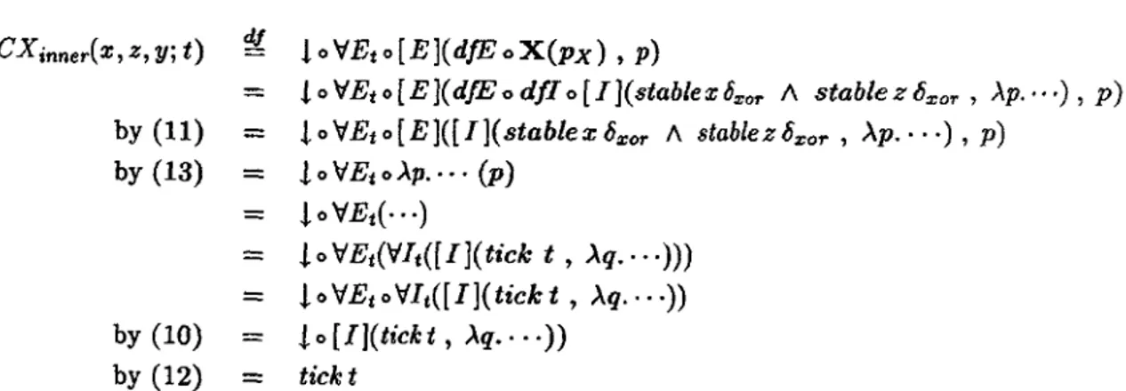
The elimination rule is stated with the help of an operator ! which is meant to project out the assumption hidden in a proof of [ </> ]. lt represents the first projection 11" 1 from above. ( E J proves </> from a proof p of [ </> J if also a proof of the assumption J(p) hidden in p is given. The interaction of [ !), ( E ], and ! is governed by the equations
!o[J](;,/:"f-></>) = "/
(E]([IJ(;, f:;--+ </>), c: 1') == f(c)
(12) (13) wl1ich state that ! indeed yields the assumption hidden by [ I] and the elimination rule [ E J
recovers the proof hidden by [/]. Note, that (13) makes implicit use of (12). The reader might find it useful to compare rules [/] and ( E J with -::;I and :>E for implication.
4
For practiacl applica.tions it does not seern tobe a restriction to conline applica.tion of [J] to propositions
; of the base logic. Since it is teclrnically adva.ntageous our implementation imposes this restriction.
Two examples of rules which can be derived from the rules introduced are 'lifting' [ L J and 'constrained /\-introduction' [Al]:
[ ,µ 1 f/l [ <P J
[ L J: ; .t ../
Rule [ L] lifts an unconstrained derivation f : </> ... 'I/; to a constrained one, namely if <P
is provable under some (hidden) assumption then the conclusion 'I/; is provable under the same (hidden) assumption. Rule [ /\] J is the /\ introduction for constrained propositions melting the hidden assumptions of [ c/>] and [ 'I/;] into a single hidden assumption for their conjunction. This interpretation of [ L] and ( /\I] is captured by the equations
1 o [ L ](!: <P ... 1", p: [ </>]) == !(p)
1 o [ J\J ](p : [ </>] , q : [ 'I/;]) == l(P) J\ 1( q)
(14) (15) That [ L J and [ l\I] are derived rules is shown by the derivation trees in Figure 3. The derivations translate into the following 'programs' implementing the two rules:
[L](f: </>- t/;, p: [,P]) '!/, [J](l(p), >.x: l(p). ~E(":Jl(f), [E)(p,x))) [ /\I](p : [ </>] ' q: [ ,p]) g [ I](!(p) /\ l(q) ' AX: L(p) /\ Hq).
Al([E](p, /\E1(x)), [E](q, /\Er(x))))
for which the equations (14) and (15) immediately follow from (12) above. Let us take [ L] as an example to explain how the program is constructed. The arguments to the [ L) rule is a derivation f : </> -+ 'ljJ and a proof p : [ 4> J. The deri va.tion tree for [ L] ( upper tree) in Figure 3 describes which rules have to be composed in which order to transform these two arguments into a proof of ( t/; ]. The term given above for defining [ L] is exactly this composition. The top rule [IJ is applied to a pair consisting of an assumption (to be hidden in [?/;]),in this case J(p), and a derivation of 'ljJ from this assumption. This derivation g : t(p) -+ 1/J is given by the subtree with 'input' x : i{p) and 'output' t/;. The associated subterm for g is the .>.-term g = >.x : l(p). ":JE(~I(J) , [E]{p,x)). The A-abstraction corresponds to the discharging ofthe assumption x: !(p) by (J].
We should perhaps remark at this point that in the the real proof session all of the proof terms are automatically constructed and manipulated by LEGO. The user only develops the p:roof tree top-down in an interactive way and does not have tobe concerned with the underlying proof terms. This also applies to the equations which in LEGO are built-in automatic reductions. Thus, whenever proof terms are explicitly spelled out in the rest of the paper it is to show the mathematical mecharusm of handling constraints a.s parts of proofs. All of this, however, is done by LEGO and need not bother the user.
Let us end this section with some remarks concerning the LEGO implementation of the
logic. In tl1e LEGO implementation the ba.se logic is a higl1er order intuitionistic calculus
encoded in the type theory of the Calculus of Constructions, or more precisely in Luo's
extension L.CC c [22] of it. An introduction on using type theories as logical calculi can
be found in {21]. The following papers present examples of encoding particular Iogics in
p: [iP 1 !(p) [E]
z: (!(p) /\ !(q))
..;
:z:: !(p) [E]
..;
Figure 3: The derived rules [ L] and [ /\l]
the type theory of LF [24,1], CC [6], or Martin-Löf [27,28]. For implementating the [.]
operator it suffices to assumes a type universe Type which is closed under the formation of simple function types A ---+ B, dependent function types IIx: A.M, and streng sum types Ex:A.M. Further, there is a type Prop, the type of all propositions of the base logic which is embedded in Type both as a type (the type of propositions) and as a subuniverse (each proposition is the type of its proofs), in symbols
Prop : Type and Prop c Type.
All this is provided by the type theory EGG c·
If <P : Prop and 1/J : Prop are propositions then the proposition cf> ::::> 'ljJ : Prop is encoded
as the function type <P ---+ t/J, i.e. a proof of <P ::::> t/J is a function that maps proofs of <P to proofs of tjJ 5• This is all what is needed for encoding Definition 1, an which the logic of constra.ined propositions is based, as a particular type of proofs. Definition 1 is represented by the following E-type:
[ef>] df = E1: Prop."f ::::> ef>.
A :E-type ~a : A.B ( a) is the type of all pairs ( a, b) where a is of type A and b is of type B( a).
The crucial feature of a :E-type is that the type of the second component (here B(a)) may depend on the value of the first (here a ). Thls is the feature needed to express [ </>] as a type:
the type of pairs where the second cornponent is a proof of a proposition (r ::::> </J) which
5
Thus, in our LEGO implementation of the logic derivations f: t/1- 1/J and proofs p : <P :::> t/J are actually
the sarne
depends on the first component (the assumption ;). This is why the implementation resides on the fact that LEGO provides E-types 6 . The properties of constrained propositions then follow from the properties of ~ types within the LEGO type system.
Now, having available a logic for dealing with constrained propositions, we turn back to the ex:ample and demonstrate its use.
4 Verification of the Example
To keep explanations reasonably short we will not mention all details that have to be presented in the actuaJ. (complete) LEGO implementation. Among those are for instance all definitions to do with basic data types such as integers and booleans. We simply assume a LEGO context in which the usual mathematical properties regarding these data types are available in the ba.se logic. We ma.y then focus on those parts of the verification that are done using the constrained logic introduced in the previous section. The example presented ltas been completely formalised and veri:fied in LEGO.
The task, set u p in Section 2.2, is to find a. derivation for 3z : signal. cnt_abs ( x, y, z) 1- cnt_appr ( x, y) where
xor_abs(x,y,z) = (stablex6xor /\ stabley8a;or) :::> Vt: int. tick t :::> zt = xt + yt
latch_abs(d,q) = (one_shot /\ min_sep61atch) :J \fti.t2: int.
(16)
(tick t 1 J\ tick t2) J (next_abs(t1, t 2) J q(t2) = d(ti))
cnLabs(x,y,z) = xor_abs(x,z,y) A latch_abs (y,z)
cnt_appr(x,y) = (Co/\ C1(x,y)) :::> (Vt1,t2 :int.C2(ti.t2)
J (nexLabs (ti.t2) ::> y(t2) = x(t2) + y(t1)))
which is split into a main proof, free of constraints, and a successive constraint analysis to establish. constraints Co, Ci, C2 for the composite device. The flrst goal is achieved by reformulating xor_abs, latch_abs, cnLabs, a.nd cnLappr a.s constrained propositions:
xor_abs' (x, y, z) '!1
latch_abs' ( d, q) ~ cnLabs' (x, y,z) ~ cnt_appr' (x, y) -g
['v't: int.[zt = xt + yt]J
[Vtbt2: int.[next_abs(t1, t2) J q(t2) == q(t1)]]
xor_abs'(x,z,y) J\ latch_abs'(y,z)
[W1, t2 : int.[ next_abs (t1, tz) J y(t2) :::::: x( t2) + y( ti)]]
Syntactically speaking, all constraints are now removed from the formulae and replaced by the [ ] construct. Semantically speaking, a.nd this is the crucial idea., a constraint now is no longer part of the proposWon but of the proof. For insta.nce,
[V't : int.[ zt = xt + yt]] (17)
6 The current implementation also makes use of LEGO's type nniverses and the built-in synthesis of
nniverse levels, also called "typica.l ambiguity".
does not give any more information regarding constra.ints than in<licating that there may be hidden assumptions, na.rnely one for each instance of the [ ]-operator. lt is the proof of (17) that actually determines these constra.ints. In fact, the constra.ints depend on from which low-level a.xioms about the exclusive-or gate the abstracted proposition (17) is derived, and by which abstraction process. Here xor is used but one might take a more detailed description of the gate, e.g. with va.riable delays, and then of course some other constraints would result. Also, there may me more than one way to verify an abstract behaviour of a composite device from properties about its components and ea.ch may result in a different constra.in t.
4.1 Abstract Verification of Modulo-2 Counter
As the 'constraint-free' version of (16) we now demonstrate a derivation of
3z : signal. cnLabs' ( x, y, z) 1- cnt_appr' ( x, y) {18) lt differs from the ideal derivation (4) only in the presence of the [. ]-construct.
First note that we can dispense with the existential quantifier since (18) is logically equivalent to a derivation
cnt_abs'(x,y,z) 1- cnLappr'(x,y) (19)
i.e. every proof of (18) gives rise to a proof of (19) and vice versa. Thus it does not really matter whether we hide internal signals in the implementation (left hand side of the turnstile) in the first place or not; they are alwa.ys eventually 'opened' when verified against a spedfication (right hand side). Consequently, we decide to take (19) as the verlfication goal right a.way.
Now let us introduce the following syntactic abbreviations:
(} ~ ne:cLabs (ti, t2)
(
~ y(t2) = x(t2) + y(t1)
ef> ~ yt = xt + zt
,,µ ~ z(t2) = y(ti)
where x, y, z are, from now on, fix.ed variables of type signal and ti, t 2 fixed variables of type int. With these abbrevia.tions (19) essentially amounts to finding a derivation
This will depend on a derivation
Q (</>{t2/t} A 1/J) -+ E:
whkh shall be assumed given.
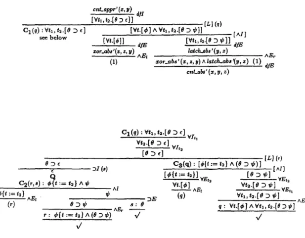
Figure 4 shows the complete natural deduction tree for (19), using Q and applying
the rules of Section 3, where all typing information is removed to improve legibility. The
refinement mechanism in LEGO allows constructing the derivation and the corresponding
cnLappr' (z, 11) dJI
[Yti,t2.[ll ::> c)J (L) (q) [Vt.[t/»] /\ Vt1,t:2-[9 ::> ,P}] [AIJ C1(r.r) :Vti,h.f8 ::> f)
see below (Vt.[~]} rl./E [Vti,t2-(/l :J ,P]) rl./E zor_abs'(:t, z, y) E latch.abs'(y, z)
---A (1)
1xor_abs' (z, z, y) A latch-abs '(y, z)
II :J
f----f,...---- 'Jl (•)
C2(r,s): ef»{t Q := h} /\ ,P
---...---Al 4'{t:=t2} . "'
___;_ ___ ___;;_ AE1 - - - - ;>E (r) - - - A E r 8 J"' s: e
r: t/>{t := t2} /\ (9:>1/1)
..;
cnLabs' (x, y, z)
Figure 4: Veri:fication of correctness for modulo-2 counter
(l) AEr dJE
proof term interactively in a top-down fashlon. The proof term collects together the rules in the order in which they are applied. In this case the proof tree of Figure 4 defines the proof function
C: cnLabs'(x,y,z) _... cnt_appr'(x,y) whlch (if typing information is again supressed) reads:
C(pc) =
C1(q) =
C2(r,s) = C3(q) =
dp o [L ](Aq.C1(q), [AI](d/E o AE1 o dfE(pc), d/E o AEr o dfE(pc))) 'rf It 1 o 'VJ, 2 o [ L ](Ar. :::>!( ~s.Q o C2(r, s)) , Cs( q))
AI(AE1(r), )E(AEr(r), s))
[ /\I]('VEt2 o/\E1(q), 'VEt2
0'VEti ol\Er(q))
This derivation provides a solution to the first part of the task: lt corresponds to the main proof that composing a delay-free modulo-2 sum and an one-unit delay as in Figure 2 yields a stoppable modulo-2 counter. The only steps in the ahove derivation that would not a.rise in an ideal proof, i.e. one which does not consider constra.ints at all, are the two occurrences of the [ L] rule. This rule is necessary to lift a proof from the base logic, for instance Q, to a constrained proof.
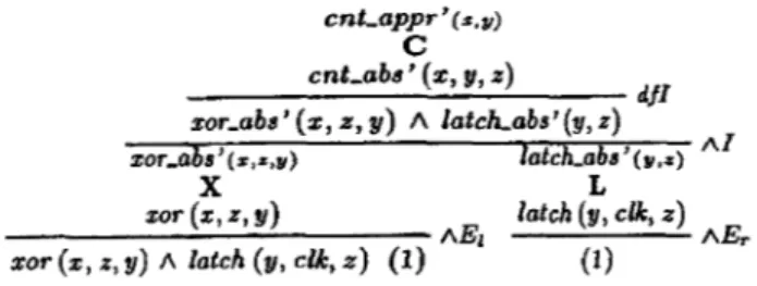
The derivation can be cal.led abstract since it is performed without looking at or even manipulating explicit constraints. Remember that cnt_abs' and the other formulae do not actually carry constra.ints. The square brackets only indicate where constraints are to be expected and so intuitively serve as a place-holder for constrain ts. In manipulating the place-holder instead of real constra.ints the (abstract) derivation C is independent of constraints and yet retains enough in.formation for extracting the constraints inside C(pc) : cnt_appr' (x, y) out of those in Pc: cnt_abs' (x, y, z), which can now be done in a completely separate phase: in the constraint analysis.
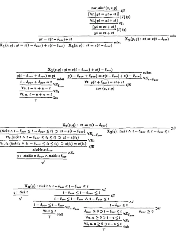
Before we can demonstrate this we need to give proofs X xor (x, z, y)---+- xor_abs' (x, z,y)
L latch (y,clk,z)--+ latch_abs'(y,z)
and thus establish that and how the exdusive-or and la.tch are implementations of the abstract components. In these proofs the actual constraints for the place-holders inside xor_abs' and latch_abs' and consequently inside
cnt_abs' ( x, y, z) = xor _abs' ( x, z, y) /\ latch_abs' (y, z) will be determined.
4.2 Synchronous Abstraction of Exclusive-Or and Latch
We begin with the derivation X. The ma.in means for introducing constraints of course is the [IJ rule which will be used twice, namely for hiding the constraints stable x bxor /\
stable z Ozor and tick t. The derivation will also have to assume 6:xor ?: 0, use substitution rules -all abbreviated as 'subst'-, and the following facts about int:
l Vt,u: int. t - u + u = t
nv:~'--~~~~~~~-
T Refi: \:/t: int. t::::; t
T S b u . Vt, u : int. u ?: 0 ::> t - u < - t
. T
xor_abs' (x, z, y) dfl
[Vt.[yt = xt+ zt]J [I] (p) Vt.[ yt = xt + zt J
---VI,
[yt = xt + ztJ [I] (q)
yt =!lt+ zt
____________ __;:.._ ____________ -:----:- subst
X 2 (p,q): xt = x(t-6„ar) yt = x(t - li,,,
0r) + zt
--~---_.;.,
__ _..:;.. ___________ subst X1 (p, q): yt = x(t - 6„or) + z(t - D:ror) X4{J1, q) : zt = z(t - 6:ror)
X1(p,q): yt = x(t- 6:.or) + z(t- 6„o„)
---:::..:::..:...;:.:__::..__~--..:.._-...:....~--'---~subst
y(t - D:.or + 6:ror) :::: yt
- - - ' - - - - subst l - 6:ror + 6:ror = t VE
S:or
y(t - li,,,
0r + 6:ror) = :t(t - 6„„) + z(t - D:ror) VE
•-611:or Vt. y(t + 6„or) = xt+ zt dfE
Vu. t - u + u = t
- - - - VEi
Vt, u. t - u + u = t xor(x,z,y)
---Inv T
X2(P, q) : xt = x(t - 6„
0„)
---..:..:;~.;._
__ ...,;:.._ _ __;;.,_ _____________ JE (tickt/\ t- 6„
0„ $ t - 6a:or $ t) ::> xt = x(t -6„or) VE
t-O:ror 'tt2 .(tickt /\ t - 6„
0„ < t2 < t) :::> xt = x{t:i)
X3(q): tickt II t - 6:r:or :$ t - 6:ror ::St
- - VEi
Vt1, t
2.(tick ti /\ t1 - 6mor $ t~ :5 t1) :> x(t1) = x(h) dfE
atable x 6:11or
- - - AEr p : stable x 6 o:or II atable z 6:ror
X3(q): tickt/\ t-6„
0„$t-6„or $ t
--~-=..:....;.
_ _ _ _ _ _ _;;;_ _ _ _
~--~AIq : tick t
../ t -
6:ror $ t - 6:JJor :$ t - - - - d.fl
t - 6zor $ t - O:i:or A t - O:z;or $ t
---=;;_---=---Al t - 6zor $ t - 6„or VE
•-O:ror
Vt. t < t T Reß
t - Ö:ror :5 t
---"'---~JE
O:i:or
![Figure 3: The derived rules [ L] and [ /\l]](https://thumb-eu.123doks.com/thumbv2/1library_info/3866666.1518442/14.921.343.669.158.555/figure-derived-rules-l-l.webp)